SECTION 11-B 1954 BUICK HEATER, AIR CONDITIONER
11-6 1954 BUICK HEATER AND DEFROSTER
1954 Buick Heater Installation
The 1954 Buick heater is mounted in the floor of body under the left side of front seat. In contains an electric blower which draws air from the body through the hot water core and recirculates the heated air at floor level. The hot water is supplied directly from the engine water manifold and the volume of hot water is controlled by the temperature control valve described in subparagraph e.
1954 Buick Defroster and Outside Air Ventilation
The 1954 Buick defroster operates in conjunction with the outside air ventilation system which is standard equipment on all models. The ventilation system operates as follows.
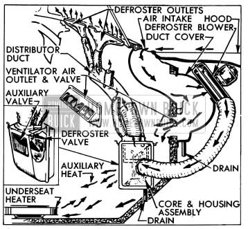
The air stream flowing over the hood during forward motion of the car enters an air intake duct built into the cowl along the base of the windshield. Two ventilator air duct covers mounted on left and right sides of the dash panel under the hood, redirect the air stream directly into the passenger compartment through air outlets in the dash panel. The volume of air entering the passenger compartment is controlled by fly valves which are connected by bowden wires to control knobs on the 1954 Buick instrument panel. Water separated from the air as the air stream reverses direction in the S-shaped passages is caught by a trough and drained through a hose at the bottom of each air duct cover. See figure 11-11.
1954 Buick Heater, Defroster, and Ventilator Installation
The 1954 Buick defroster blower mounted on the right hand air duct cover is connected by a flexible tube to the defroster core and housing assembly mounted on the right side of cowl behind the cowl trim pad. The defroster inner housing is connected by a flexible tubing to a distributor duct and four outlets mounted along the base of the windshield. See figure 11-11.
When the defroster blower is turned on, outside air is forced through the defroster core where it is heated by hot water from the engine and is then forced upward against the windshield which deflects the flow rearward into the body at shoulder level. The volume of air passing through the defroster core is controlled by a fly valve in the defroster inner housing which is connected by a bowden wire to the middle control knob on instrument panel.
The defroster inner housing contains an auxiliary valve which may be opened to provide heating from the defroster core at floor level. This valve is connected by a bowden wire to the right hand control knob on instrument panel. See figure 11-11.
Water Flow and Temperature Control Valve
The hot water supply for the 1954 Buick heater and defroster cores is taken from the outlet side of the engine water manifold, from which it is conducted by hoses to the underseat heater, then to the temperature control valve mounted on the dash panel, to the defroster core and finally to the bottom of radiator core.
The volume of hot water flowing through the 1954 Buick heater and defroster cores is regulated by the thermostatically actuated temperature control valve. When the car is cold the temperature control valve stands open to permit maximum flow of water through the heater and defroster cores. As the body air temperature comes up to the level for which the temperature control is set the valve operates to reduce the water flow and maintain the desired air temperature.
1954 Buick Heater, Defroster, and Ventilator Operation Controls
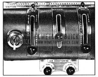
The 1954 Buick temperature control valve is manually set to the desired body air temperature by moving the left hand control knob upward into the “WINTER RANGE.” See figure 11-12.
1954 Buick Heater, Defroster, Ventilator, and Air Conditioning Controls
Once set for a desired body temperature the temperature control unit will automatically maintain this temperature without further adjustment of the control lever. Since the air temperature will come up to the level as rapidly as existing water temperature will permit it is unnecessary and undesirable to attempt quick warm-up by manipulating the temperature control lever.
Hot water flow through the 1954 Buick heater and defroster cores is completely shut off when the temperature control lever is in the “OFF” position. This shuts off all heat when not desired, such as for summer driving. This feature eliminates the need for a shut-off valve in water line at engine.
The 1954 Buick heater blower is controlled by the 3-position toggle switch mounted above the left hand control knob. The blower may be set for “HI” speed or “LOW” speed by setting the switch to right or left position as indicated on instrument panel. See figure 11-12.
The single speed defroster blower is controlled by the toggle switch mounted above the right hand control knob on instrument panel. The defroster valve in defroster housing is opened by moving the middle control knob upward. The auxiliary valve in defroster housing is opened by moving the right hand control knob upward. Both valves may be partially but not fully opened at the same time. As one valve is moved to the wide open position, it would contact and completely close the other valve.
Right and left ventilator fly valves in air outlets are operated by the right and left control knobs, respectively. Either valve may be opened by moving its control knob into the “SUMMER” range.
NOTE: To keep out offensive traffic odors and exhaust gases when traveling in congested traffic or when parked behind a car having its engine running, all ventilator and defroster valves must be closed and the defroster blower must be turned off.
WARNING-CARBON MONOXIDE
Avoid inhaling exhaust gases when any concentration of these is present in the air, i.e., in a garage, in congested traffic, or when stopped closely behind a vehicle with its motor running. Exhaust gases may have strong odors which normally should give warning of their presence. However, the exhaust gases from some vehicles may not be noticeable under certain conditions and the senses of people react differently. Exhaust gases contain a percentage of carbon monoxide, which is a poisonous gas that, by itself, is tasteless, colorless, and odorless.
Temperature Control Valve Wire Adjustment
The 1954 Buick temperature control valve is operated by a lever through a sheathed operating wire. To insure full range of temperature control, the valve must act as the stop at both ends of lever travel. Since the operating wire is of fixed length with loops at each end, full range of operation is obtained by clamping the operating wire sheath in proper location on the control lever support and the temperature control assembly as follows:
- Connect operating wire to control lever and clamp end of sheath 1/8″ from edge of clamp on lever support.
- Turn temperature control valve all the way clockwise until the cam locks against the roller. This is the extreme “off” position. Connect operating wire to brass post on valve and clamp the sheath to valve assembly.
- Operate the control lever through full range to make certain that the valve provides the stop at both ends.
11-7 1954 BUICK AIR CONDITIONER
The 1954 Buick Air Conditioner is factory installed optional equipment. Locations of the various units of the Air Conditioner system and their connecting pipes are shown in figure 11-13.
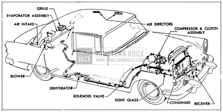
1954 Buick Air Conditioner Installation
Figure 10-95 shows the electrical control circuits, which are entirely separate from all other chassis and body wiring circuits.
Detailed service information on the Air Conditioner system is covered in separate Buick school publications. Except for the few operations given in this paragraph, all service work on the Air Conditioner system should be performed only by mechanics who have been trained in Buick or other automotive air conditioning schools. Whenever a pipe is disconnected from any unit except the compressor, liquid or vaporized refrigerant will escape unless the proper procedure is used. Any work involving the handling of refrigerant requires special equipment and a knowledge of its proper use.
Operating Instructions
Operation of the 1954 Buick Air Conditioner is controlled by two switch knobs located on instrument panel. See figure 11-12.
To start Air Conditioner operation, turn the left hand switch knob to “FAST” or “SLOW” as required by car temperature. For maintaining comfort after car is cooled down, the “SLOW” fan speed should be used except in the most extreme summer heat.
The temperature level of the air supply may be set at any point between 68° and 78° F. to suit the personal comfort of car occupants. This is done by turning the right hand knob (fig. 11-12). It is not necessary to set the temperature control to coldest position in order to cool out the car. When the knob is set for the desired temperature level, the Air Conditioner will soon bring the interior temperature to that level and will maintain it until the knob is given a different setting.
If car has been standing in the sun it may be aired out by opening doors and windows. When the Air Conditioner is started, however, all windows and ventilators must be closed in order that all outside air entering the passenger compartment will be admitted only through the Air Conditioner.
Distribution of cooling air is controlled by two ceiling air directors on each side of body. Each rear director has a shutter which may be opened or closed by the protruding button. The rear air director may be turned in any direction desired or may be closed by turning to the “OFF” position. Each front director has a door which can be opened toward front of body. It is held in any desired position by a friction spring. Additional front air directors may be rotated to any desired position but cannot be closed.
Filter and “Winterizing” Service
If a car is operated where the air is dusty or insect-laden, the transparent ducts along the rear window may need cleaning. The transparent ducts may be removed for cleaning by removing two screws located at upper end of each duct.
A disposable type air filter located under the return air grilles should be replaced every 5000 miles, or oftener if car is operated in extremely dusty conditions. The filter may be easily removed and installed after removal of access plate in rear side of the evaporator assembly.
During winter months the air valves should be closed so that cold air will not be drawn into the passenger compartment through the outside scoops. The air valves are controlled by knobs protruding from the air intake ducts.
Removal and Installation of Compressor
Whenever it become necessary to remove the 1954 Buick Air Conditioner compressor so that work can be done on the engine, the following instructions must be carefully followed. Whenever it becomes necessary to lower the engine for such work as removal of transmission, the lines should be disconnected from the compressor to avoid damaging the flexible adapters in these lines.
- Remove protective caps and firmly close both pressure line shut off valves on compressor by turning valves clockwise. See figure 11-14.
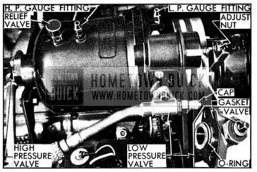
1954 Buick Compressor Line Connections
CAUTION: Make sure that both shut off valves are fully opened before starting compressor.
- After operating compressor for ten minutes at 1600-1700 engine RPM apply Buick leak detector solution (Group 9.282) around the shut off valve flanges. If bubbles form within a few seconds, a gas leak exists which must be corrected.
Adjustment of 1954 Buick Clutch Solenoid and Relay
When the 1954 Buick Air Conditioner compressor is operating, a clearance of .015″-.025″ must exist between the clutch actuating lever and the pin which protrudes from front end of compressor clutch. This clearance may be adjusted at the nut which connects the solenoid plunger to the actuating lever. See figure 11-14. Loosen the lock nut and turn the adjustment nut while holding the solenoid plunger. When specified clearance exists, tighten lock nut.
The following specifications must be used when adjusting the relay, No. 1116892:
Point Closing Voltage: 8 to 10
Air Gap, with lower points touching: 008″ to .012″
Point Opening: 010″ to .015″
Winding Resistance: 375 ohms.
Leave A Comment
You must be logged in to post a comment.