SECTION 8-A 1954 BUICK MANUAL STEERING GEAR AND LINKAGE
8-1 1954 BUICK MANUAL STEERING GEAR SPECIFICATIONS
Tightening Specifications
Use a reliable torque wrench to tighten the parts listed to insure proper tightness without straining or distorting parts. These specifications are for clean and lightly lubricated threads only; dry or dirty threads produce increased friction which prevents accurate measurement of tightness.
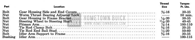
1954 Buick Steering Gear Tightening Specifications
1954 Buick Steering Gear Specifications

1954 Buick Steering Gear Specifications
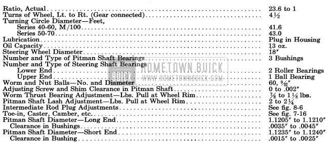
1954 Buick Steering Gear Specification
8-2 DESCRIPTION OF 1954 BUICK MANUAL STEERING GEAR AND LINKAGE
1954 Buick Steering Gear Assembly
The 1954 Buick steering gear is the recirculating ball worm and nut type. The worm on lower end of the steering shaft and the ball nut which is mounted on the worm have mating spiral grooves in which steel balls circulate to provide a frictionless drive between worm and nut. See figure 8-1.
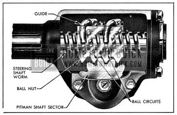
1954 Buick Steering Gear Worm and Nut, Showing Ball Circuits
Two sets of 30 balls are used, with each set operating independently of the other. The circuit through which each set of balls circulates includes the grooves in worm and ball nut and a ball return guide attached to outer surface of nut.
When the wheel and steering shaft turn to the left the ball nut is moved downward by the balls which roll between the worm and nut. As the balls reach the outer surface of nut they enter the return guides which direct them across and down into the ball nut, where they enter the circuit again. When a right turn is made, the ball nut moves upward and the balls circulate in the reverse direction. See figure 8-1.
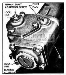
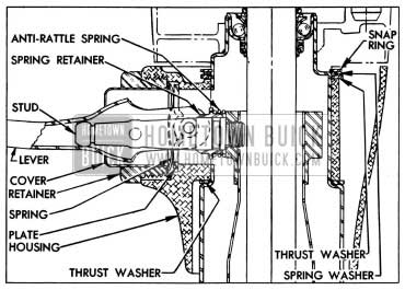
Teeth on the ball nut engage teeth on a sector forged integral with the pitman shaft. The teeth on the ball nut are made so that a “high point” or tighter fit exists between the ball nut and pitman shaft sector teeth when front wheels are in the straight-ahead position. The teeth of sector are slightly tapered so that a proper lash may be obtained by moving the pitman shaft endways by means of an adjusting screw which extends through the gear housing end cover. The head of adjusting screw and a selectively fitted shim fit snugly into a T-slot in the end of the pitman shaft, so that the screw also controls end play of shaft. The screw is locked by an external lock nut. See figure 8-2.
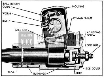
1954 Buick End Sectional View of Steering Gear
The pitman shaft is carried in two bronze bushings in 1954 Buick steering gear housing and one bronze bushing in housing side cover. A spring-loaded leather seal in housing prevents leakage of lubricant at outer end of the shaft. See figure 8-2.
The lower end of the steering shaft is carried by two spherical roller thrust bearings which bear against spherical seats on the ends of the shaft worm. The outer race of the upper thrust bearing is pressed into the gear housing. The outer race of the lower thrust bearing is formed in the thrust bearing adjuster which screws into the housing end cover and is locked by a nut. See figure 8-10. The upper end of steering shaft is supported by a ball bearing mounted in the upper end of the steering column jacket. The upper end of steering shaft has a serrated taper seat for the steering wheel which is retained by a nut and lock washer.
The 1954 Buick steering gear column jacket is clamped to a short lower jacket pressed into the gear housing. The column jacket houses the steering shaft and transmission control shaft, and the upper end provides a mounting for the control lever housing. A split bracket having an anti-squeak liner supports the column jacket below the instrument panel.
A bracket on the frame side rail helps to support the steering gear housing which is attached to bracket and side rail by clamps and four long bolts. The front lower bolt serves as a pivot and the other bolts pass through slotted holes in the frame bracket and side rail to provide adjustment for vertical alignment of steering gear assembly. The clamps bear against the cylindrical extension of gear housing so that housing can be turned in clamps to provide for sideways alignment of the assembly.
1954 Buick Steering Linkage
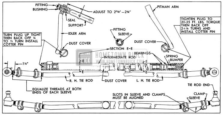
The Parallelogram type steering linkage is used to connect both front wheels to the steering gear pitman arm. As shown in figure 8-6, the right and left tie rods are connected to a tubular intermediate rod.
1954 Buick Steering Linkage
The left end of the intermediate rod is supported by the pitman arm and the right end is supported by an idler arm which pivots on a support attached to the frame. The pitman and idler arms are always parallel with each other and move through symmetrical arcs.
Each ball stud riveted to the tie rods, pitman and idler arms seats between pairs of ball socket type bearings contained in the intermediate rod. The bearings are held in firm contact with the ball studs through pressure applied by heavy coil springs located at the pitman and idler arm stud bearings. Steel spacers transmit this spring pressure to the tie rod ball stud bearings. See figure 8-6.
Flanged steel bumpers extending through the three springs act as spring guides, permit a restricted movement of ball studs and bearings as the springs absorb road shock, and prevent the bearings from spreading and releasing the ball studs in the event of spring breakage. The spring tension and clearances at ends of bumpers are adjusted by the threaded end plugs. See figure 8-6.
The opening through which the ball studs enter the intermediate rod are protected by pressed steel dust covers to keep lubricant in and dirt and water out. Bearings and ball studs receive lubrication from inside the intermediate rod which is provided with two grease fittings.
The tie rod end, which connects each tie rod to a steering arm, is a spring-load ball stud and socket unit assembly. A rubber dust seal fits over the stud where it emerges from the socket, to provide protection against entrance of dirt and water. The tie rods are connected to the tie rod ends by internally threaded sleeves which provide for toe-in adjustment. The sleeves are slotted and provided with clamps at each end to lock then in place. See figure 8-6.
8-3 TROUBLE DIAGNOSIS – 1954 BUICK MANUAL STEERING GEAR AND LINKAGE
This paragraph covers improper steering actions which are most likely to be caused by the 1954 Buick steering gear assembly or tie rods. Improper steering actions which are most likely to be caused by chassis suspension members are covered in paragraph 7-6.
Excessive Play or Looseness in 1954 Buick Steering System
- Front wheel bearings incorrectly adjusted (par. 7-10).
- Worn steering knuckle bushings or kingpins (par. 7-11).
- Steering wheel loose on shaft, loose pitman arm, tie rods, or steering arms.
- Excessive pitman shaft to ball nut lash (par. 8-4).
Hard Steering-Excessive Effort Required at Steering Wheel
- Low or uneven tire pressure (par. 1-1).
- Insufficient or improper lubricant in steering gear or front suspension (par. 1-1).
- Steering gear to frame misalignment (par. 8-6).
- Steering gear or tie rods adjusted too tight, or idler arm binding on support (par. 8-4).
- Front wheel alignment incorrect in one or more angles (par. 7-17).
- Frame bent or broken (par. 12-1).
Rattle or Chuckle in 1954 Buick Steering Gear
- Insufficient or improper lubricant in 1954 Buick steering gear (par. 1-1).
- Excessive back lash between ball nut and pitman shaft sector in straight ahead position or worm thrust bearings adjusted too loose (par. 8-4). NOTE: On truns a slight rattle may occur, due to the increased lash between ball nut and sector as gear moves off the center or “high point” position. This is normal and lash must not be reduced to eliminate this slight rattle.
- Pitman arm loose on shaft, tie rod connections loose, or steering gear loose at mounting brackets.
- Loose fit at steering shaft upper bearing.
8-4 ADJUSTMENT OF 1954 BUICK MANUAL STEERING GEAR AND LINKAGE
IMPORTANT: Never attempt to adjust 1954 Buick steering gear while it is connected to intermediate rod. Steering gear must be free of all outside load in order to properly adjust worm thrust bearings and the lash between ball nut and pitman shaft teeth.
Adjustment of 1954 Buick Steering Gear
- Disconnect intermediate rod from pitman arm by unscrewing end plug until bearings will release the ball stud. See figure 8-6. Check tightness of pitman arm nut with 18″ wrench.
- Turn steering wheel gently in one direction until it stops, then turn it back one revolution. CAUTION: Never turn wheel hard against stopping point as damage to ball nut assembly may result.
- Check for lash between ball nut and pitman shaft by working the pitman arm. If a perceptible lash does not exist, loosen lock nut and turn pitman shaft adjusting screw counter clockwise, until lash can be felt when working pitman arm. See figure 7-5. This separates the worm thrust bearing load from the “high point” load caused by close meshing of ball nut and pitman shaft teeth.
1954 Buick Steering Gear Adjustments
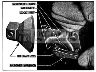
1954 Buick Adjusting Worm Thrust Bearings
CAUTION: Do not back out adjuster far enough to permit thrust bearings to get out of line with ends of worm.
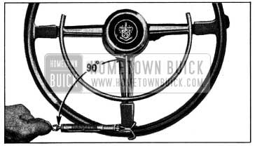
1954 Buick Checking Thrust Bearing or Lash Adjustment with Scale
Adjustment of 1954 Buick Steering Linkage
The intermediate rod must be maintained in a level position to insure good steering action. This requires proper location of the idler arm on its support so that the idler arm ball stud will be level with the pitman arm ball stud. The support must be threaded into the idler arm bushing until the distance from the center of support lower bolt hole to the nearest face of idler arm is 2 21/32″ to 2 3/4,”, as shown in figure 8-6. After any adjustment of idler arm on its support the front wheels should be checked to insure proper toe-in.
IMPORTANT: If the idler arm support is dismounted from the frame for other work, such as removal of the lower crankcase, wire the support to the idler arm so that it cannot turn from its existing position and possibly change the toe-in of the front wheels.
Whenever the, intermediate rod is being connected to the idler arm or pitman arm, be careful to properly seat the bearings around the ball stud and make sure that the pressed steel dust cover properly protects the opening around ball stud. On idler arm end of rod, turn the end plug up tight then back off 1/4 to 1/2 turn (1/2 turn preferred) and install cotter pin. On pitman arm end of rod, tighten end plug to 20-25 ft. lbs. torque then back off 1 7/8 to 2 1/3 turns and install cotter pin.
See paragraph 7-17 (subpar. e) for adjustment of tie rods to obtain proper toe-in of front wheels.
Road Test after Adjustment
Road test car for ease of steering. If 1954 Buick steering gear was adjusted to specified load limits and hard steering exists, the front suspension members should be checked for lubrication and alignment and tire inflation pressures should be checked. When car is moving straight ahead, the lower spoke of steering wheel should be straight down, or not over 5/8″ to either side of straight down position. If lower spoke is too far to either side, check steering wheel for proper position on steering shaft (par. (8-5) and check tie rods for equal adjustment and toe-in (par. 7-17). It is important to have the 1954 Buick steering gear in the no-lash range when car is moving straight forward.
8-5 1954 BUICK STEERING WHEEL REMOVAL AND INSTALLATION
Removal of 1954 Buick Steering Wheel
- Disconnect wire at horn cable connector on 1954 Buick steering column to prevent horn from blowing.
- On solid spoke steering wheel, carefully pry out the horn button cap, then remove the contact cup, spring, and contact plate which are attached to wheel hub by three screws and spacer bushings.
On flexible steering wheel, pry off the monogram and bezel assembly and remove the horn button operating wheel which is attached by three screws. - Set direction signal switch in “off” position to avoid possible damage to switch operating mechanism.
- Flatten the tab of lock washer, then back off steering wheel nut several turns but do not remove nut. Apply Puller J 1566 and adapter (fig. 8-7) and pull wheel back to nut. NOTE: If wheel hub is very tight on shaft, apply a moderate strain with puller then tap end of puller screw to break hub loose from shaft without distorting wheel hub. Remove puller, nut, and lock washer, then remove 1954 Buick steering wheel.
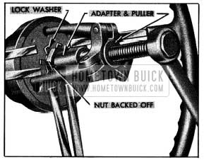
1954 Buick Removing Steering Wheel with Puller J 1566
Installation of 1954 Buick Steering Wheel
- Before installing 1954 Buick steering wheel, set signal switch in “off” position to prevent the cam from striking the switch trigger and damaging the switch operating mechanism.
- Location marks for proper installation of steering wheel on steering shaft are provided to insure a vertical position of the steering wheel lower spoke when front wheels are in straight ahead position. The upper end of steering shaft has a small location notch, the solid spoke wheel has a keyway, and the flexible wheel has a U-shaped notch. These location marks on shaft and wheel must be in line when wheel is installed. See figure 8-8.
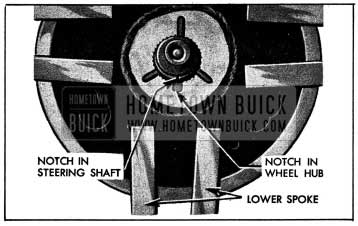
1954 Buick Location Marks on Steering Shaft and Wheel
On flexible steering wheel, install horn button operating wheel and the monogram and bezel assembly. The crest must be right side up with wheel in straight ahead position.
- Connect wire to horn cable connector on steering column.
8-6 REMOVAL AND INSTALLATION OF 1954 BUICK MANUAL STEERING GEAR
Removal of 1954 Buick Steering Gear
- Place car cover over left front fender then remove the battery.
- Disconnect transmission shift rod from control shaft lower lever, disconnect rod from selector lever (synchromesh only), then loosen the bolt in clamp which secures the column jacket to the short tube in gear housing.
- Disconnect and remove horn cable connector from steering column jacket.
- Move front seat all the way back and cover the seat and back.
- Cover the 1954 Buick steering column jacket with masking tape to prevent damage to the finish.
- Remove 1954 Buick steering wheel (par. 8-5) and the upper bearing spring and spring seat. Cover the horn contact and threaded end of steering shaft with masking tape.
- Remove signal switch and transmission shift control levers.
- Disconnect wires from the neutral safety switch and disconnect signal wires from the fuse block.
- Detach the rubber insulator retainer from dash mat and pull it up about a foot on column jacket. Remove the jute column pad.
- Measure the vertical clearance between the column jacket and the lower surface of instrument panel and record this dimension so that column can be reinstalled in same position. This dimension affects steering wheel height, which may have been changed from normal height to suit the car owner.
- Remove bolts holding the cap to steering column bracket, disconnect the bracket from instrument panel, then pull upward on column jacket to free it from steering gear.
- Remove the cranking motor splash pan from car frame.
- Remove the steering gear to frame lower bolts and clamps, then loosen upper bolts enough so that gear can be tilted sideways to provide room for pitman arm puller.
- Remove nut and lockwasher, then remove pitman arm from pitman shaft, using a suitable puller.
- With another man inside the car to guide the steering column and prevent damage to the column jacket and front seat, carefully lift the steering gear assembly up and forward out of engine compartment, leaving column jacket assembly in the body.
Installation of 1954 Buick Steering Gear Assembly
Install the gear assembly by reversing the procedure for removal, paying attention to the following points.
- When attaching the 1954 Buick steering column bracket to instrument panel measure the vertical clearance between the column jacket and the lower surface of instrument panel. The clearance at this point for normal steering wheel height is as follows:
The height of 1954 Buick steering wheel may be set as much as 3/4″ above or below normal height. If the existing clearance found before removal (subpar. a, step 10) varies from the normal height specified above, maintain the same clearance and wheel height when steering gear is reinstalled.
- When installing transmission control lever, install parts as shown in figure 8-9.
1954 Buick Control Lever and Housing Parts
On Dynaflow car, before tightening the column jacket clamp bolt, adjust the transmission control shaft lever stop plate and control linkage as described in paragraph 5-12.
- Fill steering gear housing to filler plug opening with Multi-Purpose Gear Lubricant as specified for synchromesh transmissions (par. 1-1).
- Road test car for ease of steering as described in paragraph 8-4 (subpar. c).
8-7 DISASSEMBLY, INSPECTION, ASSEMBLY OF 1954 BUICK MANUAL STEERING GEAR
Disassembly of 1954 Buick Steering Gear
- Loosen adjusting screw lock nut, then remove housing side cover by unscrewing the adjusting screw. See figure 8-10.
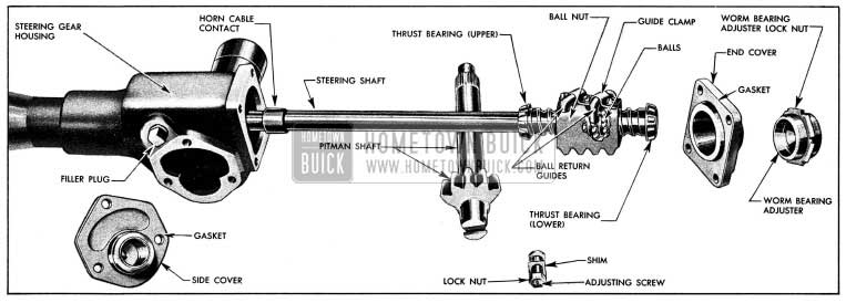
1954 Buick Steering Gear Disassembled
Cleaning and Inspection of 1954 Buick Steering Gear Parts
- Clean and inspect all ball and roller bearings and races, including race in housing, as described in paragraph 1-10. Thoroughly wash all other parts in clean solvent and wipe dry with clean cloths.
- Inspect pitman shaft bushings in gear housing and end cover. Replace bushings in housing and replace end cover if bushings are worn excessively.
- It is advisable to replace the pitman shaft grease seal in housing to avoid possible leakage of lubricant. The seal must be installed with feather edge toward inside of housing.
- Inspect steering shaft for wear or brinelling in ball and roller bearing races, which would require replacement of shaft; check shaft to make sure it is straight.
- Inspect teeth of ball nut and pitman shaft. If scored or excessively worn it is advisable to replace both parts to insure proper mating of teeth. Check serrations of pitman shaft; if twisted, replace the shaft.
- Check fit of pitman shaft adjusting screw and shim in the slot in end of pitman shaft. With shim in place, screw head must be free to turn in slot with no perceptible end play to .002″ loose. If end play is excessive, selectively fit a new shim; these are furnished in four different thicknesses.
- Inspect 1954 Buick steering column jacket for distortion. A rippled or wavy feeling of jacket surface, particularly at lower end, will usually indicate a sprung jacket. Replace jacket if sprung or otherwise damaged.
- Inspect control shaft bearing in lower end of column jacket and steering shaft upper bearing in upper end. Replace parts if worn or damaged.
- If it is necessary to remove the control lever stud for any reason it is important to tighten it to 25-30 ft. lbs. torque during reinstallation. Use a torque wrench equipped with a long 9/16″ socket which has notches cut to fit a piece of 3/16″ (.187″) drill rod inserted through the hole in stud. See figure 8-11.
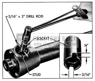
1954 Buick Installing Control Lever Stud
Assembly of 1954 Buick Steering Gear
To assemble the 1954 Buick steering gear, reverse the sequence of steps given for disassembly. In addition, observe the following instructions that apply to assembly:
- Lubricate bearings and gears with specified steering gear lubricant (par. 1-1) at time of assembly.
- Use all new gaskets to avoid oil leaks.
- When assembling ball nut on worm be sure to place 30 balls in each circuit, making a total of 60 balls.
- When installing pitman shaft avoid damaging or turning the feather edge of the leather grease seal in gear housing.
- Temporarily install steering wheel and adjust worm shaft thrust bearing for proper load and pitman shaft for proper gear lash as described in paragraph 8-4. Remove wheel.
Leave A Comment
You must be logged in to post a comment.