SECTION 4-E 1951 BUICK DYNAFLOW REMOVAL AND INSTALLATION, DISASSEMBLY AND ASSEMBLY
4-27 REMOVAL OF 1951 BUICK DYNAFLOW TRANSMISSION
- Raise right side of hood and remove bell housing dowel bolt located to rear of cranking motor solenoid, using a suitable offset brass drift. This bolt cannot be removed from under the car.
- Hoist front and rear of car and rest it solidly on stands placed under frame. Frame side rail should be at least 20″ above floor.
- Disconnect torque tube from torque ball and move rear axle back to disengage propeller shaft from universal joint.
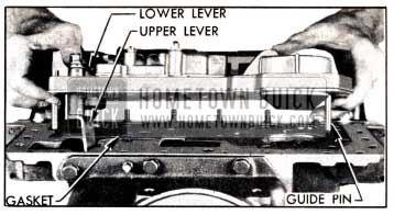
- Remove bell housing cover and bell housing hand hole cover. See figure 4-70.
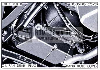
1951 Buick Right Side of Dynaflow Transmission Installation
- Turn flywheel, using Turning Tool J 4420, until one converter drain plug can be loosened sufficiently to provide an air vent, then turn flywheel until opposite drain plug is straight down. Remove this plug and allow oil to drain from converter.
- Remove plug from oil pan to drain oil from transmission.
- Disconnect hoses from oil cooler and disconnect oil filler pipe at rubber hose.
- Disconnect transmission shift rod at both ends and remove. Disconnect speedometer cable.
- Disconnect rubber thrust pad from transmission support by removing three nuts and plate, then lift out shims located between support and thrust pad. Remove two bolts and plate which attach transmission mounting pad to the support. See figure 4-71.
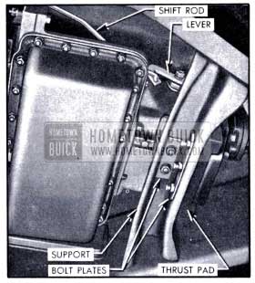
1951 Buick Left side of Dynaflow Transmission Installation
- Install engine support bar under rear end of lower crankcase. Place left side hook over frame to rear of brake master cylinder. Snug the nuts up evenly on both hooks. See figure 4-72.
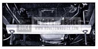
1951 Buick Engine Support Bar and Hooks in Place
- Place transmission jack or hoist in position and adjust it to securely support the transmission in accordance with instructions for the equipment being used.
- Raise the engine and transmission just enough to relieve the load on transmission support by tightening the nuts on engine support bar hooks, following up with the transmission jack or hoist.
- Remove transmission support from frame X member and remove thrust pad from thrust plate.
- Mark flywheel, converter primary pump and cover with daubs of paint so that pump can be reinstalled in same position on flywheel. Disconnect the converter from flywheel.
- Lower the transmission just enough so that the bell housing bolts can be reached with a suitable extension wrench. With engine supported by the bar and transmission supported by the jack or hoist, disconnect bell housing from engine. Loosen clamp and move exhaust pipe hanger forward to clear bolts on left side.
- Move transmission rearward to disengage hub of converter pump cover from crankshaft, lower transmission and remove it from under car.
4-28 INSTALLATION OF 1951 BUICK DYNAFLOW TRANSMISSION
- Turn flywheel so that one hole for converter drain plug is straight down and turn converter so that one drain plug is straight down. Paint marks placed on flywheel, converter primary pump and cover during removal must be in position to align when transmission is installed.
- Raise transmission into place with same equipment as used for removal. Align converter drain plug and cover bolts with corresponding holes in flywheel before moving transmission forward against flywheel housing.
- Adjust lifting equipment so that bell housing meets flywheel housing squarely, install the two bell housing dowel bolts first, then install remaining bolts. Install exhaust pipe hanger with the left hand bolts and install crankcase ventilator pipe support with lower right hand bolt. Tighten all bolts gradually to 45-55 ft. lbs. torque, with the lower right hand bolt tightened last; if this bolt is tightened first it may throw bell housing out of alignment.
- Attach thrust pad to thrust plate. Raise transmission far enough to install transmission support then lower transmission until weight is carried by the mounting pad and support. Attach mounting pad to the support with bolt plate and self-locking nuts.
- Remove lifting equipment and engine support bar.
- With engine and transmission resting freely and normally on mounting, install sufficient shims between the thrust pad and the transmission support to fill the existing space. Insert shims from above with tabs on left side, then install the bolt plate and three nuts which attach thrust pad to the support.
- Use the shank of a 11/32″ drill to align bolt holes in flywheel and converter, install bolts and tighten evenly to 30-35 ft. lbs. torque. Paint marks on flywheel and primary pump must be aligned.
- Check converter drain plugs for tightness, then install bell housing and hand hole covers.
- Connect water hose from lower side of water pump to the lower connection of transmission oil cooler, and connect the other hose to upper connection of cooler. The upper hose runs from the car heater if heater is installed, or from the engine thermostat housing if heater is not installed. See figure 11-2.
- Connect speedometer cable and connect transmission shift rod to shift lever on transmission but leave front end disconnected for later adjustment.
- Cement a new gasket in recess in front end of torque tube and make sure that propeller shaft oil seal parts are installed on propeller shaft in the following order: Spring retainer, spring, seal cap, oil seal. See figure 5-3.
- Connect torque tube to torque ball with bolts and lockwashers.
- Place oil filler pipe spring bracket over filler pipe and connect pipe to oil pan pipe, with both pipes contacting inside the rubber connector hose. Place spring bracket over front end of bell housing dowel bolt. Nut and lockwasher will be installed later.
- Wipe all oil from outside of transmission then lower the car to floor.
- Install lockwasher and nut on right hand bell housing dowel bolt, making sure that oil filler pipe spring bracket is in place, that filler pipe is in line with oil pan pipe, and that clearance exists between filler pipe and floor pan.
- Fill transmission to proper level as described in paragraph 1-4. Fill radiator to proper level.
- Check adjustment of shift control detent, then adjust shift rod and connect it to shift idler lever as described in paragraph 4-26.
- Check adjustment of neutral safety switch (par. 10-34) and back up lamp switch (par. 11-3).
- Road test car for approximately 20 miles with frequent stops and starts as might be encountered in heavy traffic. A thorough road warm-up is desired.
- Place car on hoist and carefully examine the transmission and all connections for oil leaks. Recheck oil level.
4-29 DISASSEMBLY OF 1951 BUICK DYNAFLOW TRANSMISSION TO REMOVE MAJOR PARTS AND UNITS
Preliminary Instructions
- Before starting disassembly of the transmission it should be thoroughly cleaned externally to avoid getting dirt inside.
- Place transmission on a CLEAN work bench and use CLEAN tools during disassembly and assembly. Provide CLEAN storage space for parts and units removed from transmission.
- The transmission contains parts which are ground and highly polished, therefore, parts should be kept separated to avoid nicking and burring surfaces.
- When disassembling transmission carefully inspect all gaskets at times of removal. The imprint of parts on both sides of an old gasket will show whether a good seal was obtained. A poor imprint indicates a possible source of oil leakage due to gasket condition, looseness of bolts, or uneven surfaces of parts.
- None of the parts require forcing when disassembling or assembling transmission. Use a rawhide or similar soft mallet to separate tight fitting cases-do not use a hard hammer.
- It is good practice to reassemble parts in the same relative position as they were originally assembled, however, parts must not be prick punched or filed for assembly identification. The wear pattern of the parts will usually indicate their original assembly positions.
Removal of Exterior Parts
- Remove shift lever to avoid damage to valve operating linkage while working on transmission. Hold the lever forward while removing the retaining nut and lockwasher so that linkage will not be strained, then remove lever from cross shaft. See figure 4-73.
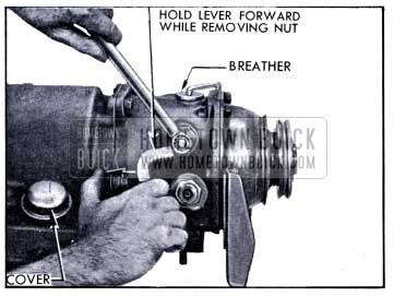
1951 Buick Removing Shift Lever
- Remove breather by carefully prying it out of rear bearing retainer.
- Remove oil cooler and pipes.
- If valve and servo body is to be removed, remove both band adjustment covers and gaskets using Removing Tool J 2655.
- Turn transmission over, with oil pan up and bell housing resting on bench.
Removal of Converter and Bell Housing
NOTE: This operation not required for removal of valve and servo body, universal joint, or rear bearing retainer.
- Remove both pipe plugs from primary pump cover to drain any oil remaining in converter.
- When converter has drained, remove all nuts, flat washers and bolts which attach the cover to primary pump. Hold cover to prevent turning by inserting a punch in drive bolt holes through the bell housing hand hole.
- Screw 5/16″-18 cap screws into the three tapped holes in pump cover to loosen and remove cover. See figure 4-74. Remove cover gasket.
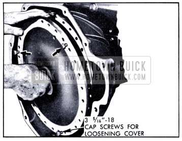
1951 Buick Removal of Converter Pump Cover
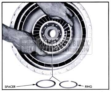
- Remove the torque converter spacer and shim washers which may be either on input shaft or in bearing recess of pump cover. Push against end of input shaft to avoid withdrawing this shaft with converter turbine, and remove turbine. See figure 4-75.
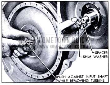
1951 Buick Removing Shim Washers, Spacer and Turbine
- Check each stator for free-wheel clutch slippage. Stators should rotate freely in clockwise direction but lock tight in opposite direction.
- Use a narrow pointed tool to remove the retaining ring from the reaction shaft. Remove both stators as one unit-their separation will result in clutch parts flying out. See figure 4-76.
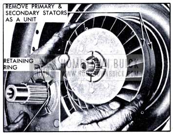
1951 Buick Removing Reaction Shaft Retaining Ring and Staton
- Check the secondary pump for free-wheel clutch slippage. Pump should turn freely in clockwise direction but lock tight in opposite direction. See figure 4-77.
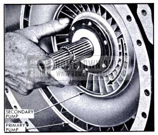
1951 Buick Checking Secondary Pump Free Wheeling Clutch
- Pull the primary and secondary pump assembly forward from reaction shaft and immediately check for evidence of oil leakage. Radial streaks of fresh oil on back of primary pump and fresh oil running down the face of front oil pump body indicate leakage past the oil pump seal.
- Before removing the bell housing check to see whether all attaching bolts are tight. Loose bolts may be the cause of oil leakage at this point.
- Put bell housing over edge of bench and remove it. Examine the rubber oil seal located around the front oil pump to see whether it has been uniformly compressed by the bell housing; if not, check for any obstacle that may be around the oil pump or opening in bell housing that would prevent uniform compression of the seal.
- See paragraph 4-30 for overhaul of converter stators and pump and paragraph 3-48 (i) for installation of bell housing and converter.
Removal of Oil Pan, Valve and Servo Body Assembly
NOTE: For removal of only the valve and servo body assembly the converter and bell housing (subpar. c) need not be removed. The following procedure also may be used with transmission in car.
- Remove the oil pan and gasket.
- Lift oil screen away from the suction pipe to which it is held by a rubber grommet snapped into the hole in screen body. Remove the suction pipe spring support, retaining spring, suction pipe, and cork gasket which seats in recess in servo body.
- Disconnect valve operating rod from valve operating lever (upper) by placing screwdriver on rod close to lever and exerting slight pressure. A spring loaded socket on rod engages a ball stud on lever. See figure 4-78.
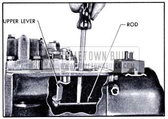
1951 Buick Disconnecting Valve Operating Rod from Upper Lever
- Slightly loosen all valve and servo body attaching bolts, then remove bolts and lockwashers. Do not loosen or remove the slotted safety nuts on valve-to-servo-body studs.
- Lightly pry upward on the assembly to free the gasket between servo body and transmission case. Push shift control valve and lower operating lever inward to align the lower lever with opening in transmission case, then remove the assembly. See figure 4-79.
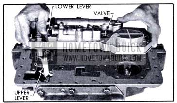
1951 Buick Removing Valve and Servo Body Assembly
CAUTION: Do not grasp slotted end of control valve because sharp edges may cut hand. Remove gasket and check for indication of oil leakage.
- Remove the reverse hand operating strut by extending fingers through the adjustment hole to prevent strut from falling into transmission case then release the strut by raising the operating lever. See figure 4-80.
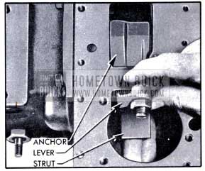
1951 Buick Removing Reverse Band Operating Strut
- See paragraph 4-31 for overhaul of valve and servo bodies and oil pan, and paragraph 4-38 (g) for installation of these units.
Removal of Reaction Shaft Flange, Front Oil Pump and Accumulators
NOTE: The converter and bell housing (subpar. c) and oil pan must be removed. Valve and servo body assembly need not be removed.
- Loosen both accumulator body caps, but do not remove caps.
- Remove the three bolts which attach each accumulator body but do not remove the stud nut. Remove the bolts extending through front oil pump cover but do not remove stud nut. See figure 4-81.
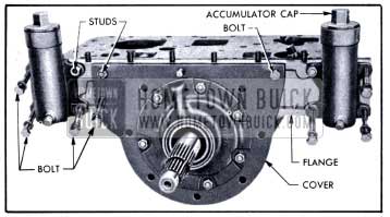
1951 Buick Accumulator Body and Reaction Shaft Flange Attaching Screws
- Tap very lightly on rear of accumulator bodies with fiber mallet to loosen reaction shaft flange, then remove the assembly and gasket. Leave input shaft in place in transmission.
- Check reaction flange gasket for good imprint and freedom from damage which would cause an oil leak at this point.
- See paragraph 4-32 for overhaul of front oil pump and reaction flange, paragraph 4-33 for overhaul of accumulators, and paragraph 4-38 (f) for installation of these units.
Removal of Input Shaft, Clutch and Low Band
NOTE: The converter and bell housing (subpar. c) valve and servo body assembly (subpar. d) and reaction shaft flange assembly (subpar. e) must be removed.
- Pull the input shaft and clutch hub front thrust washer from the clutch assembly, then remove the clutch assembly. See figure 4-82.
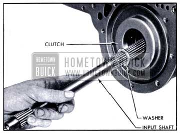
1951 Buick Removal of Input Shaft and Clutch Hub Thrust Washer
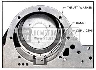
- Compress the low band with the operating lever while applying Band Clip J 2595 across the strut flanges of the band. Release the lever and remove low band, then remove the struts which will drop into case. See figure 4-83.
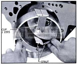
1951 Buick Removing Band with Clip J 2S95
- Remove the low band operating lever by threading a 1/4-“-20 cap screw into the lever shaft and pulling shaft out of case. See figure 4-84.
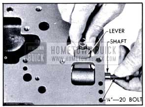
1951 Buick Removing Low Band Operating Lever and Shaft
- See paragraph 4-34 for overhaul of clutch and paragraph 4-38 (e) for installation.
Removal of Torque Ball and Universal Joint
NOTE: None of the preceding operations are required for removal of torque ball and universal joint.
- Remove the torque ball rubber boot.
- Remove attaching bolts, then remove the mounting thrust plate and gasket, torque ball and inner and outer retainers, and all paper shims. See figure 4-85. Do not lose the paper shims which govern the adjustment of torque ball.
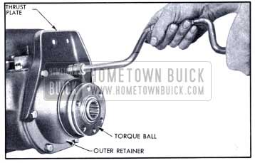
1951 Buick Removing Torque Ball
- Remove speedometer driven gear and sleeve assembly.
- Place transmission shift lever on cross shaft and push lever forward while turning universal joint until the locking pawl engages the parking lock ratchet wheel.
- Remove universal joint bolt, lockwasher and flat washer, using a 3/4″ socket wrench and extension.
- Pull universal joint from output shaft, using Universal Joint Puller J 682-A (Ser. 40-44-50) or J 859-A (Ser. 70) if joint cannot be removed by hand. See figure 4-86.
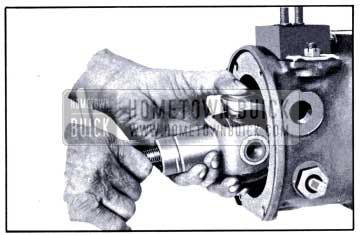
1951 Buick Removing Universal Joint With Puller
- Remove transmission shift lever.
- See paragraph 4-38 (h) for installation of universal joint and torque ball.
Removal of Rear Bearing Retainer and Parking Lock Ratchet Wheel
NOTE: Only the torque ball and universal joint (subpar. g) and oil pan need be removed.
- Disconnect valve operating rod from upper operating lever if not previously done. See figure 4-78.
- Remove universal joint retaining ring from output shaft, using hammer and large screwdriver as shown in figure 4-87. Use care to avoid nicking output shaft as nicks will damage rear bearing retainer bushing during removal of retainer.
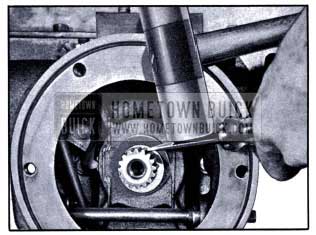
1951 Buick Removing Universal Joint Retaining Ring
- Remove retaining bolts, then remove rear bearing retainer and gasket. Check gasket for evidence of oil leakage.
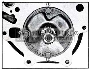
- Using snap ring pliers, remove ratchet wheel outer retaining ring, slide wheel from output shaft, and remove inner retaining ring. See figure 4-88.
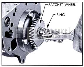
1951 Buick Removing Ratchet Wheel Retaining Ring
- See paragraph 4-35 for overhaul of rear bearing retainer and paragraph 4-38 (d) for installation.
Removal of Rear Oil Pump and Lubrication Oil Pressure Regulator Valve
NOTE: Rear bearing retainer (subpar. h) must be removed.
- Remove retaining bolts then remove pump body, which contains the pump gears. Check gaskets for indication of oil leakage.
- Remove the drive key, then use pointed tool to remove the rubber cushion which is located under drive key in the output shaft.
- Remove the rear pump plate and gasket if they can be removed from the case without prying. If plate is stuck, it can be tapped out after removal of the planetary gear set. Check gasket for indication of oil leakage.
- Remove the lubrication oil pressure regulator valve seat from transmission case, using the locally prepared drag link socket shown in figure 4 -89. Remove valve and spring.
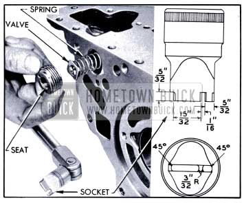
1951 Buick Removal of Lubrication Oil Pressure Regulator Valve
- See paragraph 4-32 for inspection of rear oil pump and paragraph 4-38 (c) for installation.
Removal of Planetary Gear Set, Reverse Ring Gear and Reverse Band
NOTE: All of the proceeding operations must be performed before removal of planetary gear set.
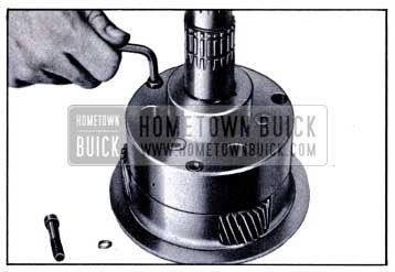
- Remove planetary gear set through front of case. See figure 4-90.
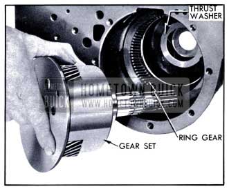
1951 Buick Removing Planetary Gear Set
- Remove the reverse ring gear, also the two planet carrier thrust washers if these did not come out with planetary gear set.
- If rear oil pump plate and gasket were not previously removed, tap them out with hammer handle from front side of case.
- Thread a 1/4″-20 bolt into the reverse band anchor shaft to pull it from transmission case then remove the operating lever. Rotate the reverse band until the anchor can be disengaged, then remove this part. See figure 4-91.
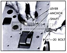
1951 Buick Removing Reverse Band Operating Lever and Shaft
- Compress ends of reverse band and apply Band Installing Clip J 2595 across the strut flanges, then remove band.
- Remove the reverse ring gear thrust washer from case.
- See paragraph 4-36 for overhaul of planetary gear set and paragraph 4-38 (b) for installation.
4-30 OVERHAUL CONVERTER STATORS AND PUMPS
Disassembly of Stators
- Rotate the primary and secondary stators as indicated in figure 4-92 while slowly drawing stators apart. Use care in separating stators otherwise free wheeling rollers and springs may fly out and be lost.
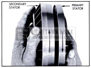
1951 Buick Separating the Primary and Secondary Stators
- Remove the free wheel race, which may be found in either stator, and remove the roller spacer from the secondary stator. See figure 4-93.
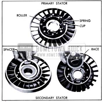
1951 Buick Free Wheeling Parts of Stators
- Remove the free wheel rollers, springs, and spring cups from both stators. Remove the roller assembling washer from primary stator. See figure 4-93.
Disassembly of Converter Pumps
- Remove the secondary pump retaining ring and free wheel roller spacer, then rotate secondary pump in clockwise direction while withdrawing it from primary pump. See figure 4-94.
1951 Buick Removal of Secondary Pump
- Remove the rollers, springs and spring cups from secondary pump.
Cleaning and Inspection of Parts
- Wash all parts in clean solvent and dry thoroughly.
- Inspect input shaft pilot bearing in primary pump cover and replace if worn or rough.
- Carefully examine all other parts for excessive wear, scoring, or other damage. Check free wheel roller springs for permanent set, distortion, or breakage.
- Small nicks on free wheel rollers and race should be removed with an Arkansas stone and polished with crocus cloth. Nicks on pump or stator vanes should be removed with a fine file.
- Replace all worn or damaged parts.
Testing Converter Primary Pump for Oil Leakage
If the primary pump is suspected of leaking oil it may be tested by means of a standard 2 1/2″ rubber tank ball with wire handle and a Barrett fitting No. 365 having a standard tire valve core.
- Insert tank ball in primary pump hub as shown in figure 4-95, and hold it in position with the wire handle.
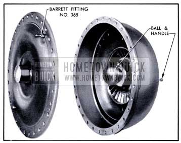
1951 Buick Ball and Fitting Installed for Pump Test
- Install primary pump cover and gasket and tighten all bolts in proper sequence to specified torque. See figure 4-151.
- Install one drain plug in cover and install Barrett fitting in other drain hole and attach air hose.
- Fill pump with compressed air at 80 to 100 lbs./sq.in. and submerge pump in water tank. Air bubbles will appear at any point where oil leakage exists.
CAUTION: After a primary pump cover gasket is used in this test it should not be used when rebuilding transmission.
Assembly of Converter Pumps
- Insert the free wheel springs and spring cups in secondary pump. See figure 4-96.
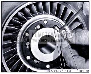
1951 Buick Installing Free Wheel Rollers in Pump
- Install secondary pump over hub of primary pump with springs outward. Slowly rotate pump clockwise during installation.
- Compress springs with a thin narrow tool and insert long free wheel rollers. See figure 4-96.
- Install the free wheel roller spacer and secondary pump retaining ring over the hub of primary pump to hold rollers and secondary pump in place.
- Check free wheel clutch action by making certain that secondary pump will turn freely in clockwise direction and lock tight in opposite direction.
Assembly of Stators
- Install the free wheel springs and cups in secondary stator and install the free wheel race. Install the race in the same position as it was before removal, as indicated by the wear pattern. A new race may be installed either end first.
- Depress the springs and cups with a thin narrow tool and install the long free wheel rollers. Place the free wheel roller spacer around the race and over the rollers.
- Install the free wheel springs and cups in the primary stator.
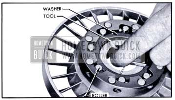
- Install Primary Stator Assembly Tool J 2592 (Ser. 70) or J 3081 (Ser. 40-M-50) in primary stator so that the three points of tool are between the roller recesses, then place the roller assembling washer flat on the tool. See figure 4-97.
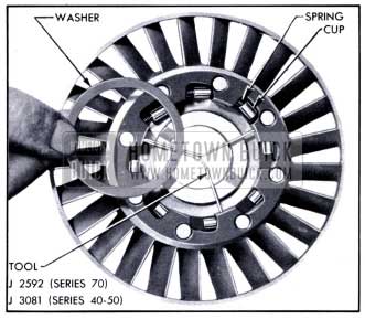
1951 Buick First Position of Primary Stator Assembly Tool
- Depress springs and cups with a thin narrow tool and install the short free wheel rollers. Install first roller adjacent to one leg of tool and the next roller diametrically opposite first roller, then install alternate rollers until all are in place. Use care to keep assembling washer flat against tool and depress springs so that rollers slide into place without being forced.
- When all rollers are in place, turn tool counterclockwise until one end can be pushed into a roller recess. This will free other ends so that tool can be removed without disturbing the assembling washer. See figure 4-98.
1951 Buick Removing Stator Assembly Tool
- Place secondary stator on bench with rollers facing upward. Place primary stator squarely in position over secondary stator, with rollers facing downward, and twist primary stator counterclockwise while pushing it down against the other stator. Keep primary stator level.
- See paragraph 4-38 (i) for installation of converter pumps and stators.
4-31 OVERHAUL VALVE AND SERVO BODIES
Disassembly of Valve Body
CAUTION: The valves have sharp edges which can cut fingers if improperly handled. As these parts are removed wrap them separately in clean cloths to avoid damage through contact with other parts.
- Remove safety nuts and washers from studs, then lift the valve body and gasket from servo body. Remove shift control valve from valve body. Check gasket for evidence of oil leakage.
- Remove the rear pump delivery check valve and spring from servo body to avoid losing these parts.
- Remove the large pressure regulator valve plug from valve body, using care because of the heavy spring pressure behind the plug. Remove the two springs and spring seat. See figure 4-103.
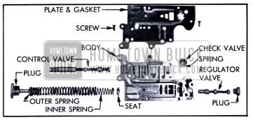
1951 Buick Valve Body Disassembled
- Remove the small valve plug and remove the pressure regulator valve from body.
- Remove valve body plate and gasket, then remove the front pump delivery check valve and spring. Check gasket for evidence of oil leakage.
- Disassembly of Servo Body
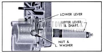
- Remove nut and lockwasher which attaches the lower valve operating lever to the upper lever shaft and remove both levers. See figure 4-102.
1951 Buick Installation of Valve Operating Levers
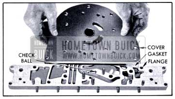
- Remove servo body spacer plate attaching screw at reverse servo which is in line with the low servo then place a 1″x1″x13″ wooden block across the low and reverse servo spring seats. See figure 4-99.
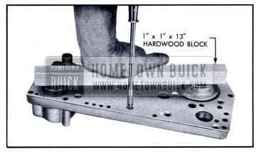
1951 Buick Removing Servo Body Spacer Plate
- Hold the block down firmly while removing the remaining spacer plate attaching screws, then carefully release pressure on block to allow servo springs to expand. This operation must be done carefully to avoid springing the spacer plate or letting the servo springs fly out. Remove spacer plate and gasket. Check gasket for indication of oil leakage.
- Remove reverse and low servo piston spring seats, springs and pistons. Remove check ball from reverse servo feed channel. See figure 4-101.
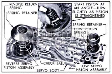
1951 Buick Parts Installed in Servo Body
Cleaning and Inspection of Valve and Servo Parts
- Thoroughly wash valve and servo bodies with clean solvent, dry and blow out all passages with air. Wash other parts and dry thoroughly.
- Carefully inspect bodies for cracks, damage to gasket surfaces, scores in piston and valve cylinders, or other damage which would render these parts unfit for use.
- Inspect surfaces and shoulders of shift control valve and pressure regulator valve. Surfaces must be free of nicks, scores, or deep scratches. A valve must be replaced if the sharp edges of shoulders are marred or rounded because such conditions will permit fine particles of foreign matter to work in between the part and the body and cause sticking. Check valves on surface plate and replace if bent.
Assembly of Servo Body
- Oil and install the low and reverse servo piston assemblies in servo body. To avoid curling or damaging edge of piston seal, start each piston into cylinder at an angle then turn piston slightly as it is straightened and pushed into cylinder. See figure 4-101. Check pistons for free movement in cylinders.
- Install the small return spring with small end against the low servo piston. Install the large return spring with the large end against the reverse servo piston. Place spring seats on upper ends of both springs. See figure 4-101.
- Worn or damaged piston seals should be replaced. When a new seal is installed on a piston make sure that the lip fits over the smaller diameter land. See figure 4-100.
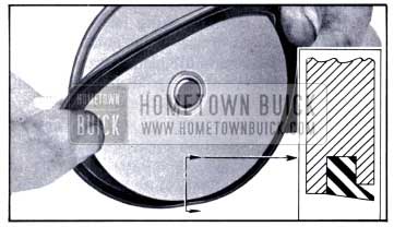
1951 Buick Installation of Servo Piston Seal
- Thoroughly clean oil screen and check for any cracks or holes which would allow dirt to pass through.
- Place check ball in reverse servo feed channel. See figure 4-101.
- Install a new spacer plate gasket and place spacer plate in position over spring seats. Place a 1″ x 1″ x 13″ wooden block across spring seats to compress the springs while installing the spacer plate screws (fig. 4-99). Tighten screws uniformly to avoid distorting spacer plate.
- Insert valve operating upper lever shaft through bearing in servo body. With upper lever pointing away from low servo, place lower lever on shaft as shown in figure 4-102, then install lockwasher and nut.
Assembly of Valve Body
- Place front pump delivery check valve spring in body with large end down and place check valve on spring with ridged side up. See figure 4-103.
- Install valve body plate and a new gasket, making sure that check valve is seated against plate and is not caught under gasket.
- Place the pressure regulator spring seat on the inner spring, then install spring seat, inner and outer springs and the large plug in valve body. Tighten plug to 20-25 ft. lbs. torque.
- See that oil orifice in pressure regulator valve end land is clear, then install valve with this land outward. Install plug and tighten to 20-25 ft. lbs. torque.
- Install shift control valve with slotted end on same end of valve body as the large pressure regulator plug.
- Install rear pump delivery check valve in its seat in servo body, ridged face inward, and place valve spring on valve with large end up.
- Install a new gasket and the valve body on servo body, using care to keep pump delivery check valve spring below the gasket, then install plain washers and safety nuts on two studs adjacent to the control valve. Tighten stud nuts evenly to 11-15 ft. lbs. torque.
- See paragraph 4-38 (g) for installation of valve and servo bodies.
4-32 OVERHAUL OIL PUMPS AND REACTION SHAFT FLANGE
Disassembly of Front Oil Pump and Reaction Shaft Flange
- Remove high and low accumulators from reaction shaft flange, using care to prevent the retaining pin and check ball from dropping out of high accumulator and being lost. Check gaskets for indication of oil leakage.
- Before removing front oil pump check the nuts for tightness-loose nuts would be the cause of oil leakage around the pump. Remove front oil pump body and gears, tapping body lightly with mallet to free it, if necessary.
- Remove front oil pump cover and gasket from reaction shaft flange, and check gasket for evidence of oil leakage.
- If the check ball located in clutch feed passage of reaction shaft flange is free to drop out, remove ball to avoid loss in handling parts. Do not remove if securely retained by peened edge of hole. See figure 4-104.
1951 Buick Front Oil Pump Cover and Reaction Shaft Flange
Cleaning and Inspection of Front and Rear Oil Pumps
- Wash pump parts in clean solvent and dry thoroughly.
- Check mounting faces of pump bodies, gears, front pump cover and rear pump cover plate for excessive wear.
- Inspect front oil pump bushing. If bushing is loose or excessively worn replace the pump assembly.
- If front oil pump bushing is loose or excessively worn, or pump was noisy always check for flywheel run-out, primary pump hub run-out, and misalignment of bell housing as described in paragraph 4-37.
- Inspect the front pump oil seal but replace it only if there is definite evidence of leakage or damage. Drive out defective seal with a punch. Lightly coat outside of new seal with No. 3 Permatex, start seal squarely into pump body with deep groove in seal retainer outward and tap into place with hardwood block and mallet. Wipe off excess Permatex.
- Make the following checks and replace worn parts if clearances exceed specified limits.
- Using straight edge (Gauge J 2596) and feeler gauge gears should have .001″ to .0025″ side clearance relative to mounting face of body. See figure 4-105.
1951 Buick Checking Side Clearance of Gears in Pump Body
- Using feeler gauge, clearance between crescent and driven gear when held away from crescent should be .003″ to .006″. See figure 4-106, view A.
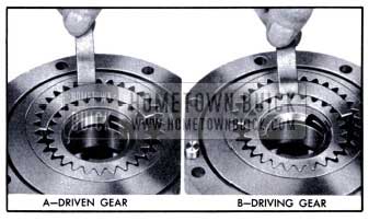
1951 Buick Checking Clearance Between Crescent and Gears
- Using feeler gauge, clearance between crescent and driving gear when held away from crescent should be .007″ to .014″ on front pump, and .007″ to .011″ on rear pump. See figure 4-106, view B.
- Check front pump cover and rear pump cover plate for depth of wear caused by the gears. Replace the part if depth of wear exceeds .001″ or surface is scored.
Cleaning and Inspection of Reaction Shaft Flange
- Wash flange in clean solvent, dry thoroughly and blow out all passages with air.
- Inspect surfaces of reaction shaft flange and transmission case for nicks or burrs and remove with mill file.
- Inspect the bronze bushing on rear hub of reaction shaft flange and the cast iron sealing sleeve pressed into the hub. If these parts are worn excessively or scored, replace reaction shaft flange.
- Inspect the oil sealing rings on hub of reaction shaft flange and replace if damaged in any way.
- Check all studs for tightness and replace any with damaged threads. If stud threads are stripped in reaction shaft flange, it will be necessary to tap out the hole for installation of step studs which are available. The 5/16″-18 step studs have a 3/8″-16 thread on the flange end. The 3/8″-16 step studs have a 7/16″-14 thread on the flange end. A 3/8″-16 and a 7/16″-14 tap are required for installation of these step studs.
NOTE: If reaction shaft flange is replaced, stamp transmission identification number in lower edge of new part in same place as on original flange. See figure 4-39.
Assembly of Front Oil Pump and Reaction Shaft Flange
- Install check ball in clutch feed passage if ball was removed, then install a new gasket and the pump cover on reaction shaft flange. See figure 4-104.
- Lubricate and install gears in front pump body. The driving gear must be installed with the beveled side outward so that this side will be against the cover when pump is installed. See figure 4-107. Reversing this gear in pump body will result in severe damage to the transmission.
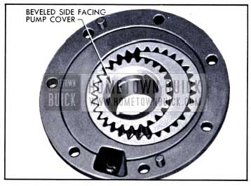
1951 Buick Correct Installation of Driving Gear in Pump Body
- Install oil pump on cover so that the two dowel pins engage holes in cover, then install nuts with lockwashers. Tighten nuts to approximately 5 ft. lbs. torque in the sequence shown in 4-108 and then tighten in same sequence to 25-30 ft. lbs. Tighten cover attaching stud nut to 25-30 ft. lbs. torque.
1951 Buick Front Oil Pump Tightening Sequence
- See paragraph 4-38 (f) for installation of front pump and reaction shaft flange assembly.
4-33 OVERHAUL HIGH AND LOW ACCUMULATORS
- Remove retaining pin and check ball from high accumulator body. The low accumulator does not have the check ball.
- Remove the pipe plug, cap, gasket, spring and piston from accumulator body. Keep parts separated so that same parts will be reinstalled in same body. See figure 4-109.
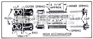
1951 Buick High and Low Accumulators-Disassembled
- Wash accumulator parts in clean solvent, dry thoroughly, and blow out all passages with air. Examine all parts of each accumulator for excessive wear, scoring, or other damage.
- Remove any nicks or burrs from pistons or valve with an Arkansas stone; however, do not round the sharp edges of lands on pistons and valves. If the sharp edges are marred or rounded foreign particles may wedge between the part and the body and cause sticking.
- With parts clean and dry, install pistons and check for free sliding as body is tipped back and forth.
- Check mounting surface of body with a straight edge. If surface is uneven it may be trued up by moving body in a circular motion over emery cloth placed on a surface plate. Thoroughly wash body to remove all traces of emery.
- If the body or piston is worn or damaged, or piston does not slide freely in body after all burrs are removed, replace accumulator assembly. The body and piston are not furnished separately for service replacement.
- Lubricate each piston and install it in the accumulator body from which it was removed. Start piston squarely into body; do not tap or force it into body.
- Install proper springs in each body as shown in figure 4-109, then install caps with new gaskets. Caps will be tightened later-do not clamp accumulator in vise to tighten caps.
- Install pipe plugs in both accumulator bodies and install check ball and retaining pin in the high accumulator body. See figure 4-109.
- See paragraph 4-38 (f) for installation of accumulators.
4-34 OVERHAUL CLUTCH AND INPUT SHAFT
Disassembly of Clutch
- Remove reaction gear flange retainer ring with screwdriver and remove the 3 flange driving keys with pointed tool. See figure 4-110.
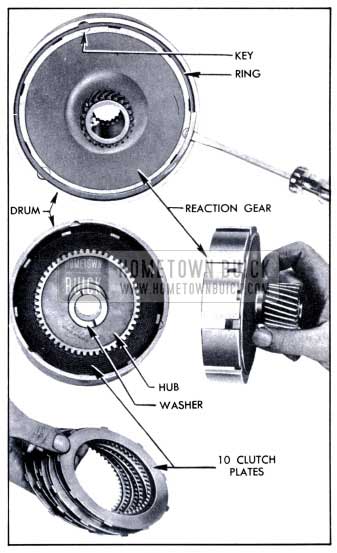
1951 Buick Removal of Reaction Gear, Hub, and Plates
- Remove the low range reaction gear, thrust washer, clutch hub, and 10 clutch plates from drum. See figure 4-110.
Install Clutch Spring Compressor J 2590 in assembled drum, placing the slot in compressor ring over the ends of spring seat retaining ring. Compress clutch spring sufficiently to remove the retaining ring. See figure 4-111.
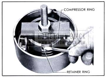
1951 Buick Using Clutch Spring Compressor J 2590
- Release pressure on clutch spring, making sure that spring seat does not engage retaining ring groove in drum, then remove spring compressor, spring seat and spring.
- Remove piston from drum. It may be necessary to ‘rap the open end of drum against a block of wood to remove the piston.
Cleaning and Inspection of Clutch and Input Shaft
- Wash all parts in clean solvent and dry thoroughly. Use only gasoline or kerosene to clean clutch plates and bands-DO NOT use any chemical degreasers or other commercial solvents.
- Inspect all clutch plates and replace any that are scored, burned, warped or worn excessively. Check fit of any new internally splined plates on clutch hull to make certain that they slide freely on hub. Tight plates will prevent full disengagement of the clutch.
- Inspect drum for cracks or scores. Inspect oil sealing ring on hub of drum and replace it if damaged. To remove ring, apply finger pressure at points indicated by arrows in figure 4-112, in order to unlock the ends by depressing one end and raising the other. Use the same method to lock the ends during installation of new ring.
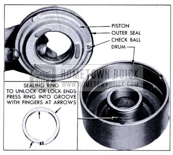
1951 Buick Removal of Clutch Piston and Oil Sealing Ring
- Make sure that small bleed hole in piston is open and that check ball is staked in place but free to move in recess.
- Inspect clutch piston outer seal and replace if hardened, broken, or has turned edges. Install new seal with lip extending over the smaller diameter land of piston. See figure 4-113.
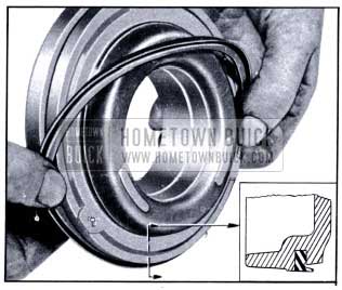
1951 Buick Replacement of Clutch Piston Outer Seal
- Inspect the low band. If band lining is worn smooth so that the grooves are gone replace the band.
- Inspect the input shaft oil seal ring and if damaged or broken replace it as shown in figure 4-112. Make sure that retaining ring is in place on shaft. See figure 4-114.
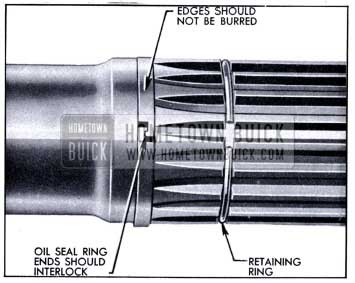
1951 Buick Input Shaft Oil Seal and Retaining Rings
Assembly of Clutch
- Apply light oil to the piston outer seal and the inside of drum, then install piston carefully to avoid distorting or turning the lip of seal. When piston is fully installed in drum, the top of piston will be approximately flush with the shoulder on inside of drum.
- Place clutch spring in piston and place spring seat and seat retaining ring on spring. Install Clutch spring Compressor J 2590 (fig. 4-111) and compress spring until the retaining ring can be snapped into the groove in hub of drum, then remove the spring compressor.
- Place reaction gear on bench with flange upward, then install clutch hub thrust washer and clutch hub over the hub of reaction gear with open end of clutch hub facing up. See figure 4-115.
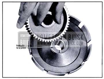
1951 Buick Installing Thrust Washer and Clutch Hub In Reaction Gear
- Separate the internally splined (faced) clutch plates from the externally splined (plain steel) clutch plates. Internally splined plates are flat and may be installed in either direction.
Externally splined plates are “dished” and all these plates must be installed with the “dish” in the same direction; however, the “dish” may be either up or down. Check each plate for “dish” with a straight edge, figure 4-116, and stack plates so that all are “dished” in same direction.
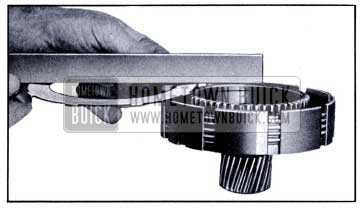
1951 Buick Checking Dished’ Side of Externally Splined Clutch Plate
- Install an internally splined clutch plate over clutch hub, next to gear flange, then install an externally splined plate. Alternately install the remaining plates, making sure that externally splined plates are “dished” in same direction. If properly installed, the top plate will be externally splined.
- Place the drum and clutch piston assembly over the reaction gear flange so that the driving key recesses in drum and flange are approximately aligned. See figure 4-117. Press the drum evenly into place over the reaction gear flange.
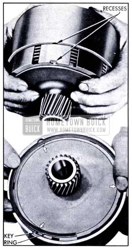
1951 Buick Installing Drum Over the Reaction Gear Flange
- Complete the alignment of driving key recesses by tapping the reaction gear flange, then install the 3 driving keys and the reaction gear flange retainer ring. See figure 4-117.
- See paragraph 4-38 (r) for installation of clutch and input shaft.
4-35 OVERHAUL REAR BEARING RETAINER, UNIVERSAL JOINT AND TORQUE BALL
Disassembly of Rear Bearing Retainer
- Remove the snap fastener which connects the valve operating rod clevis to the valve operating cross shaft, then remove rod and clevis assembly through front end of bearing retainer. See figure 4-118.
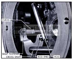
1951 Buick Connections to Cross Shaft
- Disconnect the parking lock operating rod from the cross shaft by unscrewing the rod end from cross shaft lever. The rod end is provided with a lockwasher. See figure 4-118.
- Remove cross shaft bearing, using a box wrench; a socket which does not fully engage bearing, or an end wrench will distort the bearing. Remove the cross shaft. See figure 4-l19.
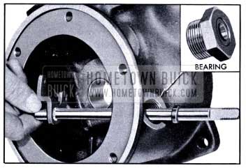
1951 Buick Removing Valve Operating Cross Shaft
- Screw a 1/4″-20 bolt into the parking lock pawl shaft and pull the shaft from rear bearing retainer, allowing end of pawl to swing free. See figure 4-120.
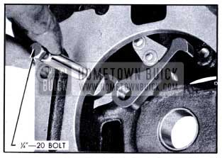
1951 Buick Removing Lock Pawl Shaft
- Tap the parking lock operating lever toward front of rear bearing retainer, using long punch, and remove the operating lever shaft. The operating lever, lever and pawl assembly, and apply spring can then be removed.
Cleaning and Inspection of Rear Bearing Retainer Parts
- Wash all parts in clean solvent and dry thoroughly.
- Inspect the parking brake lock pawl, pawl locking link, and ratchet wheel for cracks and for worn teeth that would prevent positive locking.
- Inspect valve operating cross shaft and bearing for excessive wear. Remove the rubber seal from bearing and discard it.
- Inspect the rear bearing retainer bushing for scoring or excessive wear. Insert the output shaft in bushing and check the clearance, which should be .001″ to .006″. Replace the bushing if it is excessively worn, using Bushing Remover and Replacer J 2997. See figure 4-121. Reaming to size is not required.
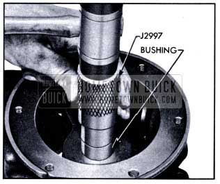
1951 Buick Bushing Remover and Replacer J 2997
lnspection and Repair of Universal Joint and Torque Ball Parts
- Inspect universal joint for wear and play between spider pins and the bushings. Allowable play is .002″ to .004″.
- Check fit of universal joint yokes on the output and propeller shafts. Allowable backlash of rear yoke on propeller shaft splines is .0005″ to .0045″. The front yoke must be a tight fit, rotatively, on output shaft to prevent “snap” when alternating car movement between forward and reverse.
- Inspect rear yoke of universal joint for excessive wear at point of contact with oil seal in torque ball. Rear yoke and bushing in torque ball must be free of scores and not worn excessively; clearance between these parts should be .004″ to .006″.
- Clean and inspect spherical surfaces of torque ball and both retainers. If these are scored or pitted the parts should be replaced.
- Inspect oil seal in torque ball and replace if worn. When installing a new oil seal in torque ball, place seal in position with the feather edge pointing into torque ball, then press seal squarely into place, using a flat piece of metal to avoid distorting seal. Press new seal flush with boss on flange of torque ball. NOTE: Oil seal should be stored in neatsfoot oil to keep leather soft and pliable. Do not use seal having a hard, dry leather.
Assembly of Rear Bearing Retainer
- Assemble the locking pawl and lever assembly, apply spring, and parking lock operating lever with operating rod on dummy shaft as shown in figure 4-122; note position of each end of apply spring.
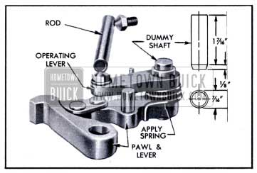
1951 Buick Assembly of Parking Lock Control Parts and Dummy Shaft
- Place assembled parts in position in rear bearing retainer then install the operating lever shaft through retainer and lever.
- Install parking lock pawl shaft through bearing retainer and lock pawl, making sure that tapped end is outward to permit future removal.
- Install the valve operating cross shaft, and cross shaft bearing. Install a new seal in the bearing, with grooved side facing inward.
- Connect the parking lock operating rod to cross shaft lever, using a lockwasher on the threaded rod end. See figure 4-118. Do not connect the valve operating rod and clevis to cross shaft at this time.
- See paragraph 4-38 (d) for installation of rear bearing retainer.
4-36 OVERHAUL PLANETARY GEAR SET AND TRANSMISSION CASE
Disassembly of Planetary Gear Set
- Remove three planet carrier screws and special lock washers, using a 7/32″ hexagon (Allen) wrench. See figure 4-123.
1951 Buick Removing Planet Carrier Screws
A used universal joint front yoke may be placed on output shaft and held with a bar while loosening the screws.
- Separate the front and rear ends of planet carrier by carefully tapping around the front flange while holding the unit clear of bench.
- Remove the sun gear rear thrust washer, which may be either on sun gear or stuck in rear end of carrier. Remove reverse sun gear. See figure 4-124.
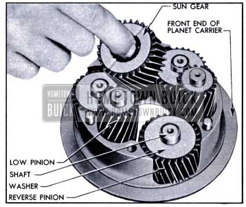
1951 Buick Removal of Sun Gear and Planet Pinions
- Remove the 3 low planet pinion assemblies, each consisting of a pinion, shaft, and bearing rollers retained at each end of pinion by steel thrust washers. See figure 4-124. A retaining ring snapped into a groove in shaft will hold the lower thrust washer in place as shaft is tapped out of carrier. The shaft is prevented from turning in carrier by a 3/32″ steel ball imbedded in end of shaft. Do not lose the steel ball.
- Remove the 3 reverse planet pinion assemblies which are similar to the low planet pinion assemblies and are removed in the same manner.
- Remove the thrust washers and shafts from pinions, then remove the bearing rollers.
Note that the reverse planet pinions have a single set of rollers and the low planet pinions have two sets of rollers separated by a spacer. See figure 4-125.
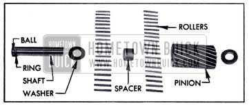
1951 Buick Low Planet Pinion, Disassembled
Cleaning and Inspection of Planetary Gear Set
- Wash all parts in clean solvent and dry thoroughly.
- Carefully inspect shaft and rollers for excessive wear. Replace if worn.
- Inspect reverse ring gear, sun gear, and pinions for wear; remove any nicks or burrs with Arkansas Stone.
- Inspect bushing in rear end of planet carrier, and replace it if worn or scored. The bushing may be removed with Busing Remover J 3197 and new bushing may be installed, either end first, by using Bushing Replacer J 2996. See figure 4-126. Reaming to size is not required.
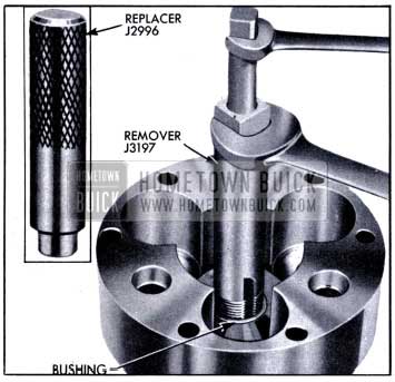
1951 Buick Replacing Planet Carrier Bushing
- Inspect reverse band and replace it if cracked or lining is worn so that grooves are gone. Inspect reverse band anchor for cracks.
Cleaning and Inspection of Transmission Case
- Wash case thoroughly and blow out all passages.
- Carefully inspect case for cracks, breaks, and stripped threads in bolt holes.
- Inspect all machined surfaces for nicks or burrs and smooth off with a mill file.
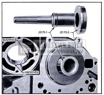
- Inspect the bushing for wear and scoring. Insert planet carrier into bushing and check clearance with feeler gauge. If clearance is excessive due to wear of bushing, replace the bushing.
- To remove old bushing, place case over an opening with rear end down and drive bushing from case with J 3175-1. To install new bushing place J 3175-2 in rear oil pump recess of case to serve as a pilot, slip bushing over J 3175-1 and drive bushing into case from front side until bushing is flush with front surface of wall which supports the bushing. Bushing must be installed with the wide deep ends of oil grooves toward rear side of case. See figure 4-127.
1951 Buick Transmission Case Bushing Remover and Replacer J 3175
Assembly of Planetary Gear Set
- Re-assemble planet pinions and shafts with bearing rollers and thrust washers. The bottom thrust washer goes between retaining ring on shaft and the end of pinion. Each reverse planet pinion contains 24 rollers. Each low planet pinion contains 20 rollers at each end separated by a spacer. See figure 4-125. Place a thrust washer on upper end of each assembly to hold rollers in place.
- Make sure that steel ball is embedded in each shaft to prevent turning in carrier, then install planet pinion assemblies in front end of planet carrier, using care to engage the steel balls in the notches in carrier. See figure 4-124.
- Install reverse sun gear and place bronze thrust washer on top of gear.
- Install rear end of planet carrier on the assembled front end, making sure that the assembly marks on both parts are in alignment. These marks are numbers which are placed over the parting line during production of the carrier.
- Install the 3 screws with special lock washers and tighten to 25-30 ft. lbs. torque with a 7/32″ hexagon (Allen) wrench.
- Install reverse ring gear on planetary gear set.
- See paragraph 4-38 (b) for installation of planetary gear set.
4-37 CHECKING RUNOUT OF FLYWHEEL AND PRIMARY PUMP, AND ALIGNMENT OF BELL HOUSING
Converter oil leaks, front oil pump body leaks, front oil pump noise, and excessive wear of front oil pump bushing and oil seal may be caused by: (1) Excessive runout of flywheel face (2) Excessive runout of converter primary pump hub (3) Misalignment of bell housing.
When any of these conditions are encountered and there is any doubt as to their true cause, check the flywheel, primary pump and bell housing as follows:
- Check runout of flywheel face as described in paragraph 2-36 (b) and make required corrections before proceeding further.
- Install converter primary pump on flywheel and tighten the six mounting bolts to 25-30 ft. lbs. torque. Install bell housing.
- Prepare a special dial indicator clamp by welding a piece of 5/16″ x 3″ drill rod to a 1″ C-clamp. Use the special clamp and Sleeve KM0-30-K to mount Dial Indicator KM0-30-B so that indicator stem bears against the primary pump hub as shown in figure 4-128.
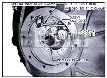
1951 Buick Checking Runout of Primary Pump Hub
- Turn flywheel and note indicator reading. Runout of primary pump hub should not exceed .012″. If runout is .012″ or less, mark flywheel and pump with daub of paint so that final installation can be made in same position.
- If hub runout exceeds .012″ mark flywheel and primary pump, remove pump and reinstall 180 degrees from first position, then check runout again. If runout is then’ .012″ or less, mark flywheel and pump with daub of paint.
- If pump hub runout still exceeds .012″ after Steps 4 and 5, replace primary pump and check for runout again.
- Attach the special dial indicator clamp to the oil pump driving lug on rear end of primary pump hub. Do not clamp to bearing surface of hub.
- Mount dial indicator to check runout of rear face and pilot hole of bell housing as described in paragraph 2-35. Make indicated corrections if runout exceeds the specified limits.
4-38 ASSEMBLY OF 1951 BUICK DYNAFLOW TRANSMISSION FROM MAJOR PARTS AND UNITS
General Instructions
- Before starting to assemble the transmission make certain that all parts are absolutely clean. Keep hands and tools clean to avoid getting dirt into assembly. If work is stopped before assembly is completed cover all openings with clean cloths.
- All moving parts should be given a light coating of 10-W oil before installation. Thrust washers may be held in place with vaseline or chassis lubricant, sparingly applied.
- Do not take a chance on used gaskets and seals-use new ones to avoid oil leaks.
- Use care to avoid making nicks or burrs on parts, particularly at bearing surfaces and surfaces where gaskets are used.
- It is extremely important to tighten all parts evenly and in proper sequence, to avoid distortion of parts and leakage at gaskets and other joints. Use a reliable torque wrench to tighten all bolts and nuts to specified torque and in the specified sequence.
- Prepare two 5/16″x 2 1/2″ guide pins and two 3/8″x1 3/8″ guide pins with screwdriver slot in plain end, as shown in figure 4-129. These will be used for alignment of parts during assembly.
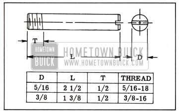
1951 Buick Dynaflow Guide Pins
Installation of Planetary Gear Set
- Install reverse ring gear rear thrust washer in transmission case.
- Compress ends of reverse band with Band Installing Clip J 2595 and install in case. See figure 4-130. Remove the clip. NOTE: Reverse band does not have strut locating pins in end slow band has pins.
1951 Buick Ring Gear Thrust Washer and Reverse Band Installed
- Rotate the reverse band toward servo opening, insert anchor through opening and engage with hooked end of band then rotate band and anchor back to normal position.
- Hold band operating lever (with offset end) in place with strut shoulder toward inside of case, and insert anchor shaft through case, anchor, and lever. Tapped end of shaft must be outward. If adjustment screw is not centered in servo opening, the low band operating lever has been installed by mistake. See figure 4-131.
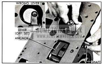
1951 Buick Installing Reverse Band Operating Lever and Shaft
- Install planet carrier front (steel) thrust washer on carrier with the three tangs engaged in holes in carrier. See figure 4-132.
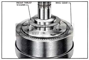
1951 Buick Installation of Front Thrust Washer
- Install planet carrier rear (bronze) thrust washer in case with the three tangs engaged in holes in case, then install assembled planetary gear set in transmission case. If gear set is properly installed and thrust washers are in place, the end of output shaft journals will be flush with rear end of transmission case bushing.
Installation of Rear Oil Pump and Lubrication Oil Pressure Regulator Valve
- Place gasket and rear oil pump plate in recess in transmission case and align the bolt holes, which are not equally spaced.
- Install oil pump drive key cushion (rubber) and drive key in output shaft, then install driving gear to engage the key. Install old gear in same position as before removal-install a new gear either way. See figure 4-133.
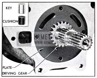
1951 Buick Oil Pump Driving Gear and Key Installed
- Lubricate both pump gears and pump body, then install driven gear and body over the driving gear and align bolt holes.
- Install pump b0lts with lockwashers, tighten evenly to 5 ft. lbs. torque in sequence shown in figure 4-134, then tighten in same sequence to 25-30 ft. lbs. torque.
1951 Buick Rear Oil Pump Bolt Tightening Sequence
- Turn output shaft to make sure pump operates freely.
- Install the lubrication oil pressure regulator valve spring, valve and valve seat in transmission case. Tighten valve seat with locally prepared drag link socket shown in figure 4-89.
Installation of Parking Lock Ratchet Wheel and Rear Bearing Retainer
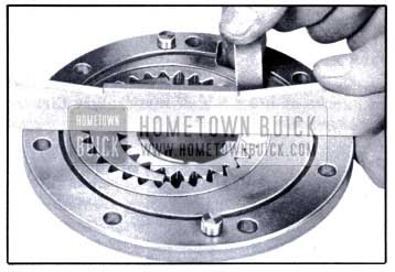
- Install a retaining ring in the forward groove in output shaft, install ratchet wheel, then install retaining ring in rearward groove in output shaft. See figure 4-135.
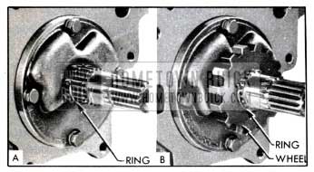
1951 Buick Installing Parking Lock Ratchet Wheel
- Insert valve operating rod through square hole in front face of rear bearing retainer and connect clevis to cross shaft lever with snap fastener. Socket on forward end of operating rod must face bottom of bearing retainer.
- Carefully examine splined end of output shaft, particularly adjacent to the groove for universal joint retaining ring. Remove burrs with a mill file to prevent damage to bushing in rear bearing retainer when this part is installed.
- Install rear bearing retainer and gasket on transmission case. See figure 4-136. Use lockwashers on attaching bolts and tighten bolts evenly to 35-40 ft. lbs. torque.
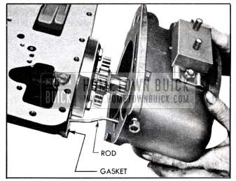
1951 Buick Installing Rear Bearing Retainer
- Install universal joint retaining ring in the groove in output shaft.
Installation of Low Band, Clutch, and Input Shaft
- Install the low band operating lever and shaft. Strut shoulder of lever must be toward inside of case and tapped end of shaft must be outward. See figure 4-137.
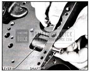
1951 Buick Installing Low Band Operating Lever and Shaft
- With the assembly standing on end of rear bearing retainer, install a wooden block (1″x2″x 3 1/2″) as shown in figure 4-138.
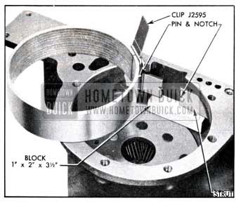
1951 Buick Installation of Low Band and Struts
Set both low band struts in position on block, with plain ends engaging strut shoulder of operating lever and groove in anchor shaft and with notched ends together and about 3/16″ from wall of case. Spread struts as far apart as possible.
- Compress ends of low band with Band Installing Clip J 2595 (fig. 4-138). NOTE: A used band must be reinstalled in original position heaviest wear will be at anchor end. A new band can be installed either way.
- Install band in case with ends between the struts and resting on the wooden block. Apply the operating lever to hold struts and band, remove clips and block, then press band down until the locating pins engage the notches in both struts.
- Place reaction gear bronze thrust washer centrally over the sun gear. See figure 4-139.
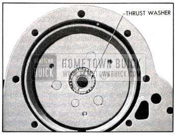
1951 Buick Reaction Gear Thrust Washer in Place
- Install clutch assembly. If drum binds against low band so that clutch does not go all the way down, use a hooked wire to lift the band on side opposite struts.
- Place bronze thrust washer on- front face of clutch hub, then use a flashlight to make sure that all four thrust washers are centrally located so that input shaft can be inserted.
- Make sure that ends of input shaft oil seal ring are properly locked, and retaining ring is in its groove, then install input shaft until retaining ring rests on clutch hub. It may be necessary to wiggle the shaft to get it through an four thrust washers.
Installation of Reaction Shaft Flange, Front Oil Pump, and Accumulators
- Install a 5/16″ guide pin (fig. 4-129) in accumulator bolt hole at each end of flange on transmission case. See figure 4-140.
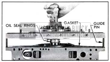
1951 Buick Installing Reaction Shaft Flange and Gasket
- Place reaction shaft flange gasket in position on case so that all holes in gasket and case are aligned. Gasket can be incorrectly installed.
- Make certain that oil seal rings are on flange hub, then install flange assembly on case using care to avoid damaging oil seal rings. See figure 4-140.
- Place accumulator gaskets in position so that holes match the holes in reaction shaft flange. Install low accumulator on same side as low band- operating lever and install high accumulator on opposite side of flange, first making sure that check ball and retaining pin are in place in high accumulator body.
- Coat accumulator bolt threads with Permatex No. 3 (non-hardening) and install bolts and stud nuts with lockwasher, but do not tighten.
- Install 3 special bolts (3/8″-16×2″) with plain washers in positions marked 2, 3, 4 in figure 4-141.
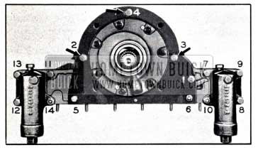
1951 Buick Reaction Shaft Flange and Accumulator Bolt Tightening Sequence
These bolts are for assembly purpose only. Install regular pump cover bolts, nuts, and lockwashers at positions marked 1, 5, 6. Coat threads of bolt No. 5 with Permatex No. 3.
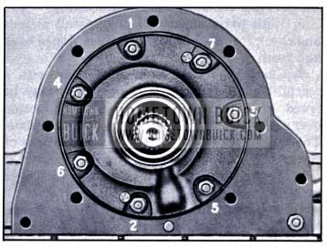
- Referring to figure 4-141, tighten all bolts and nuts (1 through 14) to 5 ft. lbs. torque in the numerical sequence shown. Following the same sequence again, tighten bolts 1 through 4 to 35-40 ft. lbs. and the remaining bolts and nuts to 20-25 ft. lbs.
- Remove the three special bolts (2, 3, 4) and tighten accumulator body caps to 40-50 ft. lbs. torque.
- If edge of flange gasket projects beyond bottom surface of transmission case, carefully trim it flush, using a sharp knife.
Installation of Valve and Servo Body Assembly, and Oil Pan
- With transmission laying bottom side up, raise the reverse band operating lever and insert the strut between shoulders on lever and end of band-rounded ends must be against lever and band. CAUTION: Do not lift the lever during the following steps because strut will fall into transmission case.
- Install two 5/16″ guide pins (fig. 4-129) in transmission case to guide each end of servo body, and install servo body spacer plate gasket over guide pins.
- Push shift control valve and lower operating lever inward to align the upper lever with opening in case and install the valve and servo body on transmission case. See figure 4-142. Engage pin in control valve with slot in operating lever.
1951 Buick Installing Valve and Servo Body Assembly
- Install various length bolts with lockwashers according to depth of holes through valve and servo bodies. Use copper washer on center bolt adjacent to suction pipe opening. See figure 4-143.
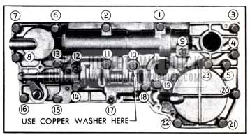
1951 Buick Valve and Servo Body Bolt Tightening Sequence
- Tighten all bolts to 5 ft. lbs. torque in the numerical sequence shown in figure 4-143. Repeating the same sequence, tighten all 1/4″ bolts and nuts to 11-15 ft. lbs. torque and all 5/16″ bolts to 15-20 ft. lbs. While tightening bolts and nuts adjacent to the shift control valve, operate the valve to make certain that it is not binding-it may be necessary to adjust some bolts to low limit on torque to prevent valve binding.
- Remove bolt No. 18 and nut No. 9 and install cork gasket, suction pipe, retaining spring and support as shown in figure 4-144. Tighten bolt and nut to 11-15 ft. lbs. torque.
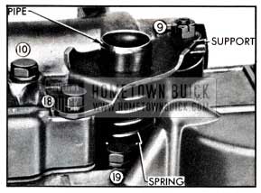
1951 Buick Oil Screen Suction Pipe Installation
- Using Linkage Hook-Up Finger J 2591, position the socket of valve operating rod under the ball of valve upper operating lever and pull upward until ball snaps into the socket. See figure 4-145.
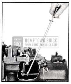
1951 Buick Connecting Valve Operating Rod to Upper Lever
- Temporarily install the shift lever on cross shaft and operate the valve linkage to make sure it works freely. Move lever toward front of transmission to engage parking lock pawl in the ratchet wheel. When pawl is fully engaged in the wheel, the pawl lock must be in full contact with pawl. See figure 4-146.
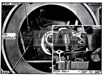
1951 Buick Control Valve Linkage Adjustments
- Push the shift control valve away from the stop pin just enough to remove play from valve linkage, then check clearance between stop pin and end of valve, using feeler gauge. Clearance should be .030″ to .040″. See figure 4-146. When clearance is correct, the spring travel at end of shift lever will be 1/8″ to 3/16″.
- If clearance is not correct, adjust to obtain proper clearance by turning the clevis on valve operating rod. Rod and clevis assembly may be removed for adjustment.
- Tighten jam nut against clevis when adjustment is completed. Remove shift lever from cross shaft.
- Spread a thin coat of Permatex No. 3. On transmission case only in the area where the case is cut away under the oil pan gasket. This is adjacent to the valve operating lever.
- Install a 5/16″ guide pin (fig. 4-129) at each end of transmission case and install a new oil pan gasket over guide pins. Install oil screen on suction pipe.
- Install oil pan with bolts and stud nuts provided with heavy duty internal-tooth lockwashers. Evenly tighten all bolts and nuts to 15-18 ft. lbs. torque.
Installation of Universal Joint, Torque Ball, and Speedometer Driven Gear
- Install speedometer driven gear and sleeve assembly in rear bearing retainer.
- Engage the parking lock pawl in ratchet wheel.
- Make sure the universal joint retaining ring is fully seated in groove in output shaft, then install universal joint using Replacer J 865 (Ser. 40-50) or J 855 (Ser. 70) to draw universal joint snug against retaining ring. See figure 4-147.
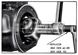
1951 Buick Installing Universal Joint
- Install universal joint plain washer, lockwasher, and bolt using a3/4″ socket and tighten bolt to 30-35 ft. lbs. torque. CAUTION: Make certain that oil passage in bolt is clear.
- Install and adjust torque ball to 10-35 pounds drag, then install torque ball boot as described in paragraph 4-13.
Installation of Bell Housing and Torque Converter
- Install front oil pump seal ring around pump body against pump cover.
- Install bell housing, using lockwashers on bolts and stud. Sparingly coat threads of lower right side bolt with Permatex No.3 because the bolt hole opens into transmission case. Tighten bolts and stud nut evenly to 35-40 ft. lbs. torque.
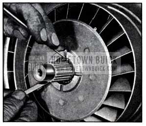
- Support primary pump cover on suitable blocks. Install bearing plug of Converter Clearance Gauge J 3045 (for Series 40-50) or J 2596 (for Series 70) in ball bearing in pump cover. Place gauge bar across cover with ends resting on flat surface between bolt holes. See figure 4-148.
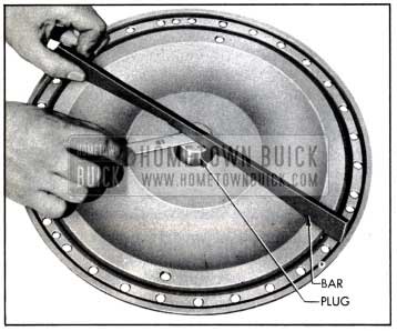
1951 Buick Checking Primary Pump Cover with Clearance Gauge
- Using clean, flat feeler gauges check the clearance between the gauge plug and bar. Do not exert any pressure on top of bar as this will cause erroneous measurement. Turn gauge 90 degrees, take a second measurement and then record the average of both measurements for later use in Step 9.
- Place stators and turbine in normal position in primary pump, and place clearance gauge bar on flange of pump, between bolt holes. Check clearance between gauge bar and hub of turbine (fig. 4-149) and record this measurement for later use in Step 9.
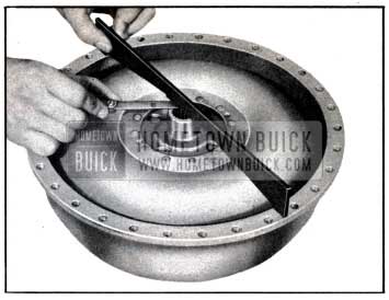
1951 Buick Checking Primary Pump and Turbine with Clearance Gauge
- Install the primary and secondary pump assembly on reaction shaft, turning primary pump back and forth until lugs on pump hub enter the slots in front oil pump driving gear.
- Install the primary and secondary stator assembly on reaction shaft and install the reaction shaft retaining ring in groove of shaft. See figure 4-150.
1951 Buick Installing Reaction Shaft Retaining Ring
- Install converter turbine on input shaft.
- Add together the measurements obtained in Steps 4 and 5-the sum is the total clearance between the turbine hub and the bearing in pump cover. This clearance must be filled with a sufficient number of .018″ shim washers and .060″ spacers, which can be determined by referring to the following “Converter Clearance Shimming Chart.” Select the required washers and spacers indicated by total clearance and place them on input shaft.
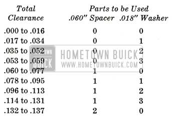
1951 Buick Dynaflow Converter Clearance Series 40-50
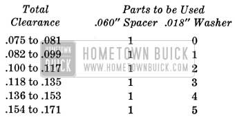
1951 Buick Dynaflow Converter Clearance Series 70
- Install the primary pump cover with a new gasket, then install bolts with plain washers and safety nuts against the cover do not tighten nuts. Place first two bolts directly in line with the drain plugs. Going clockwise, omit bolt in every fifth hole to provide for the flywheel to pump driving bolts.
NOTE: Be sure that bolts and bolt heads are all the same length.
- When all pump cover bolts are in place, insert the shank of a 11/32″ drill through one flywheel bolt hole to align all bolt holes then tighten bolts to approximately 5 ft. lbs. torque in the numerical sequence shown in figure 4-151.
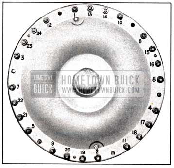
1951 Buick Primary Pump Cover Bolt Tightening Sequence
When tightening bolts, insert a wide screwdriver between flat side of bolt head and primary pump to prevent a corner of bolt from digging into pump. Finally tighten all bolts in the same numerical sequence to 30-35 ft. lbs. torque.
- Install converter drain plugs, then turn transmission over to rest on oil pan.
Low and Reverse Band Adjustment
NOTE: The following adjustment must be very carefully performed since it is not possible to readjust the bands after transmission is installed in car.
- Loosen lock nut and turn adjusting screw clockwise until considerable resistance is felt, indicating that band is in full contact with the drum (low) or ring gear (reverse). See figure 4-152.
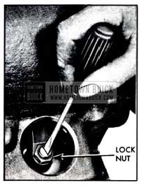
1951 Buick Band Adjustment
- Back off screw until just a trace of play can be felt by prying up on lock nut with screwdriver. From that point, back off screw six (6) complete turns and snug up the lock nut.
- After noting position of adjusting screw slot, tighten lock nut to 20-25 ft. lbs. torque. Remove torque wrench and check to make sure that adjusting screw did not turn.
- Install band adjustment cover with new gasket.
Install Shift Lever, Oil Cooler, and Breather
- Install transmission shift lever on cross shaft with lockwasher and nut. Hold lever forward while tightening nut, to avoid straining the internal linkage.
- Install oil cooler on right side flange of transmission case. Install oil pipes and tighten connections securely.
- Before installing the breather, check to make sure that the U-shaped steel baffle is installed in breather body. The baffle should be positioned so that when breather is installed with the tube extending over right rear end of rear bearing retainer the legs of baffle will be aligned with centerline of transmission. Tap breather firmly into opening in bearing retainer.
Leave A Comment
You must be logged in to post a comment.