SECTION 4-C 1951 BUICK DYNAFLOW SPECIFICATIONS, DESCRIPTION, AND OPERATION
4-15 1951 BUICK DYNAFLOW GENERAL SPECIFICATIONS
1951 Buick Dynaflow Transmission Identification Number
A production identification number is stamped into the lower edge of the reaction shaft flange directly to rear of the high (left) accumulator. The identification number consists of a letter followed by a number. See figure 4-39.
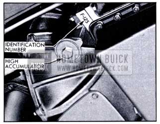
1951 Buick Location of Dynaflow Transmission Identification Number
The letter indicates the car series for which the transmission is designed and the number indicates the date of production. All transmissions in each series are given the same number during one day of production and the next highest number is used the following day. If a design change which affects interchangeability of parts goes into production during the day, the next highest number is used for the balance of the day, starting with the first transmission which contains the new parts.
Series 40 -50 transmission identification numbers run as follows: F-1, F-2, F-3-to F-999, then H-1-to H-999, etc. Series 70 transmission identification numbers run as follows: G-1, G-2, G-3-to G-999, then J-1-to J-999, etc.
Since the production identification number furnishes the key to construction and interchangeability of parts in each transmission the number should be used when selecting replacement parts as listed in the Master Parts List. The number should always be furnished on Product Reports, A.F.A. forms, and correspondence with the factory concerning a particular transmission.
General Specifications
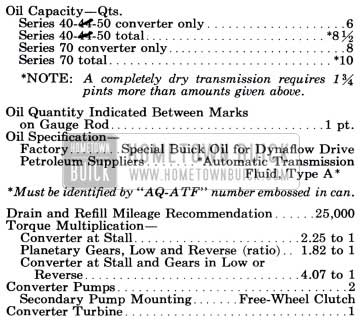
1951 Buick Dynaflow Transmission Specifications
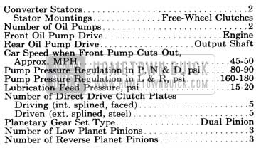
1951 Buick Dynaflow Transmission General Specifications
4-16 TIGHTENING, TEST AND ASSEMBLY SPECIFICATIONS
Tightening Specifications
Use a reliable torque wrench to tighten the attaching bolts or nuts of the parts listed below. These specifications are for clean and lightly lubricated threads only; dry or dirty threads produce increased friction which prevents accurate measurement of tightness. NOTE: Where a figure number is given, tighten in the sequence shown by the indicated illustration. Failure to use the specified torque and tightening sequence may result in distortion of parts and oil leakage.
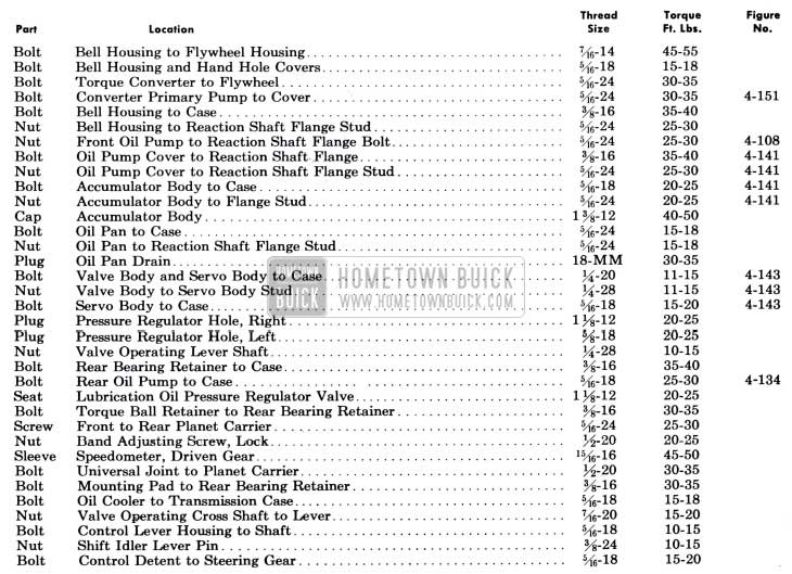
1951 Buick Dynaflow Transmission Tightening Specifications
Test and Assembly Specifications
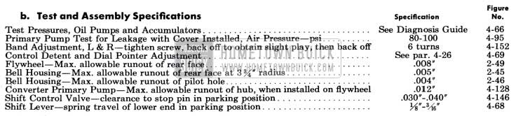
1951 Buick Dynaflow Test and Assembly Specifications
4-17 1951 BUICK DYNAFLOW PRODUCTION LIMITS AND FITS OF NEW PARTS
NOTE: These specifications apply to new parts only and must be used with discretion when checking worn-in parts. The limits established for new parts allow for reasonable wear through normal use; therefore, parts which have been in service and have been operating satisfactorily should not be re placed simply because they slightly exceed the limit is specified for new parts.
Converter Assembly
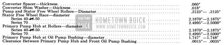
1951 Buick Dynaflow Converter Assembly
Front Oil Pump
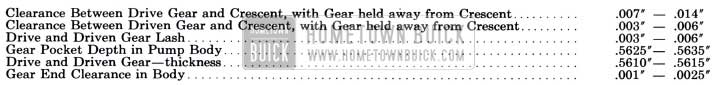
1951 Buick Dynaflow Front Oil Pump Specifications
Reaction Shaft Flange

1951 Buick Dynaflow Reaction Shaft Flange Specifications
Accumulators

1951 Buick Dynaflow Accumulators Specifications
Valve and Servo Body Assembly

1951 Buick Dynaflow Valve and Servo Body Assembly Specifications
Clutch
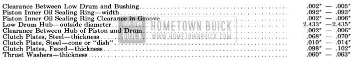
1951 Buick Dynaflow Clutch Specifications
Planetary Gear Set and Reverse Ring Gear
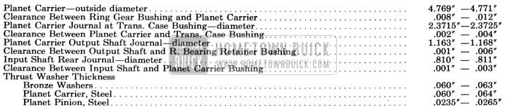
1951 Buick Dynaflow Planetary Gear Set and Reverse Ring Gear Specifications
Rear Oil Pump
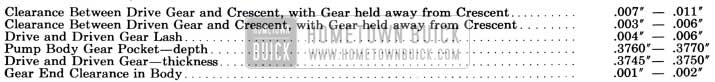
1951 Buick Dynaflow Rear Oil Pump Specifications
4-18 1951 BUICK DYNAFLOW MANUAL CONTROL MECHANISM AND OPERATING INSTRUCTIONS
Manual Control Mechanism
1951 Buick Dynaflow Drive provides five different control or operating ranges which may be manually selected by the driver through movement of the shift control l ever at top of steering column. A pointer on the control lever housing and a stationary dial mounted on steering column aid in locating the lever for each range. See figure 4-40.
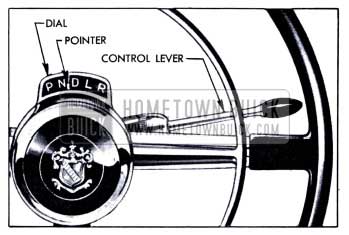
1951 Buick Dynaflow Dial, Pointer, and Lever
Letters on the dial, reading from left to right identify each range as follows:
- P = Parking
- N = Neutral
- D = Direct Drive
- L = Low
- R = Reverse
It is necessary to raise the control lever against light spring pressure when shifting into Parking (P), Neutral (N) or Reverse (R). Raising the lever depresses a stop pin in the control lever housing so that the pin can pass the stops mounted in the dial housing. The stop pin and stops prevent accidental shifting into these ranges when car is in motion and also make it possible to quickly locate the control lever in any desired position without looking at the dial.
The control lever actuates a control shaft in steering column which is connected by levers and rods to a shift control valve in the transmission. A detent at lower end of the control shaft holds the manual control mechanism in the selected position.
The manual control mechanism also operates a neutral safety switch which is included in the cranking motor control circuit. The switch is closed so that the engine can be cranked only when the control lever is in either the Neutral (N) or Parking (P) position, thereby preventing accidental movement of the car when the engine is started.
When the car is equipped with back up lights the manual control mechanism operates a back up light switch so that the circuit to the back up lamps is closed only when control lever is in Reverse position.
Parking (P) Range
Parking range is to be used in conjunction with the “step-on” parking brake to insure positive locking of car on steep grades. The shift control lever must be raised when shifting into or out of Parking position.
Parking rang e must never be entered when the car is in motion as serious damage to transmission will result.
For safety, Parking range should always be used when it is desirable to run and accelerate the engine without possibility of car movement, as when working on car in the shop.
When in Parking range, a parking lock ratchet wheel on transmission output shaft is engaged by a locking pawl mounted in the transmission rear bearing retainer, thereby providing a positive mechanical lock for the rear wheels. The locking pawl is actuated by the transmission manual control linkage through an apply spring which holds the pawl against the ratchet wheel until engagement of these parts is accomplished. If the pawl does not engage a notch in ratchet wheel when first applied it will snap into place as the wheel turns when car moves slightly.
The engine may be started while the car is locked in Parking position.
Neutral (N) Range
Neutral range as well as Parking range may be used when starting the engine. It is not necessary to shift into Neutral when the’ car is temporarily stopped with engine running during normal driving operation.
Neutral must always be used when towing the car with rear wheels on the road.
Neutral range may be used when it is desirable to run and accelerate the engine without possibility of car movement, but Parking range is recommended for this condition because of greater safety.
Direct Drive (D) Range
Direct Drive range is to be used for all forward driving conditions except as specified for low range.
Low (L) Range
Low range is used only when the engine is under an exceptionally heavy load, such as in deep snow or sand or on long steep grades. Low range can be used to obtain additional engine braking when descending steep grades.
The shift between Low and Direct Drive ranges may be made while the car is in forward motion, but the D to L shift must never be made at speeds above 40 MPH.
Reverse (R) Range
Reverse range is used to move the car rearward. The shift control lever must be raised to shift into Reverse.
Rocking Car Between Low and Reverse
When the car is stuck in deep snow or mud it can be driven out by “rocking” the car back and forth by alternately using Low and Reverse until sufficient momentum is obtained to move car out in desired direction.
After accelerating engine slightly to provide sufficient power, hold shift control lever up and move it back and forth between Low and Reverse. Control the engine speed and time the movement of control lever so that the rear wheels push firmly against the snow or mud in each direction but avoid spinning the rear wheels.
Pushing or Towing Car to Start Engine
If it becomes necessary to push a 1951 Buick Dynaflow Drive car to start the engine, place shift control lever in Neutral (N) until car speed reaches approximately 15 MPH, then shift into Low (L). Continue to increase car speed until engine cranks (approximately 25 MPH). After engine starts, return control lever to Neutral (N) for engine warm up. It is safer to push car than tow it.
Towing Disabled 1951 Buick Dynaflow Drive Car
A disabled 1951 Buick Dynaflow Drive car must not be towed on rear wheels with transmission in any of the driving ranges because unnecessary damage to transmission may result. It may be safely towed in Neutral (N) only.
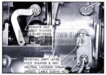
The Neutral Locking Strap should be employed to lock transmission in neutral position for towing in cases where car damage makes it impossible to obtain or maintain neutral position by means of the regular transmission contra} mechanism. Install the locking strap on transmission in the following manner.
- While holding shift lever forward to avoid straining internal linkage, remove lever retaining nut and lockwasher, then remove lever from cross shaft.
- Install neutral locking strap over cross shaft, with U-slot of strap straddling the speedometer cable sleeve nut. See figure 4-41. Hold strap in place by reinstalling shift lever.
1951 Buick Installation of Neutral Locking Strap
4-19 PRINCIPLE SECTIONS OF THE 1951 BUICK DYNAFLOW TRANSMISSION
To simplify description of construction and operation of the 1951 Buick Dynaflow transmission assembly, it will be divided into the following four sections, as shown in figure 4-42.
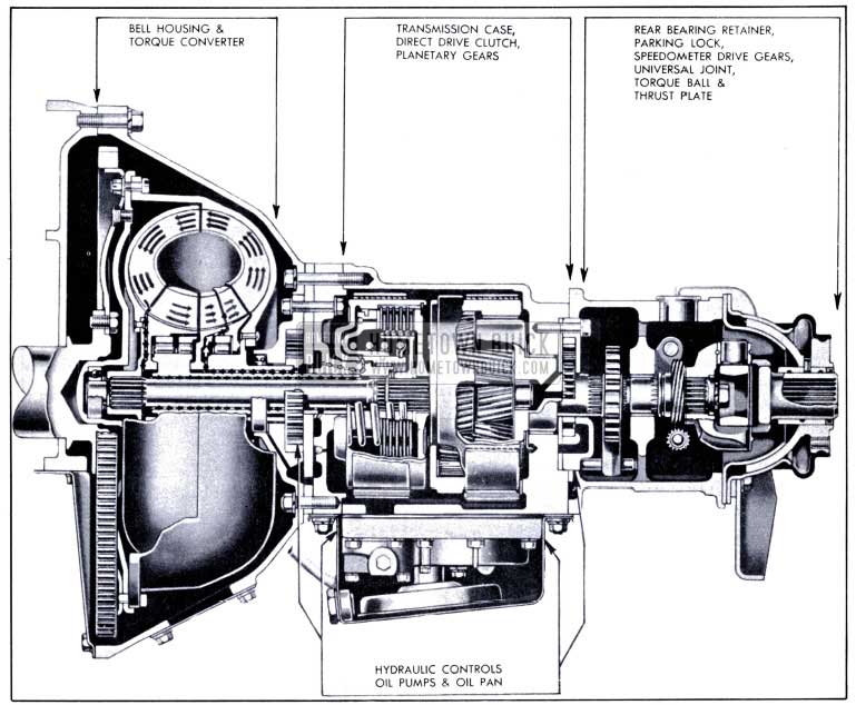
1951 Buick Side Sectional View of Dynaflow Transmission
Torque Converter and Bell Housing
The transmission assembly is solidly attached to the engine crankcase by the bell housing which incloses the torque converter.
The torque converter is connected to the engine flywheel and serves as a hydraulic coupling through which engine torque is transmitted to drive the car. In addition, it automatically provides torque multiplication as required under all ordinary driving conditions.
Construction and operation of the torque converter are described in paragraph 4-20.
Transmission Case, Direct Drive Clutch, and Planetary Gears
The transmission case is bolted to the bell housing and to the rear bearing retainer. The case incloses the direct drive clutch and a planetary gear set which provides Reverse and a forward Low Range gear ratio.
The direct drive clutch locks the planetary gears so that no gear action can occur when direct drive is required. When the clutch is disengaged and the planetary gears are released so that they cannot transmit torque, the engine is disconnected from the propeller shaft so that it cannot move the car. This condition exists in the Parking and Neutral ranges.
The Low Range gear ratio is provided for exceptional load conditions where the torque multiplication provided by the torque converter is inadequate. Low Range also may be used for engine braking on very long or steep grades.
Construction and operation of the direct drive clutch and planetary gears are described in paragraph 4-21.
Hydraulic Control System
Operation of the direct drive clutch and the planetary gears is hydraulically controlled through oil pressure provided by two oil pumps. Devices for insuring smooth engagement and disengagement of these components are incorporated in the hydraulic control system. The hydraulic control system also provides for filling the torque converter and circulation of oil for lubrication.
One oil pump is located forward of the transmission case and the other is at rear end of the case. With two exceptions, the units which regulate oil pressure, control operation of clutch and planetary gears, and provide selective control of all operating ranges are contained in a valve and servo body assembly mounted on the bottom of the transmission case and inclosed by the oil pan. The two exceptions are a high accumulator and a low accumulator which are externally mounted on a flange between the bell housing and transmission case. These units are not shown in figure 4-42.
Construction and operation of all hydraulic control units are described in paragraph 4-22.
Rear Bearing Retainer and Torque Ball
The rear bearing retainer is bolted to the rear end of transmission case and the torque ball is assembled on the rear end of the retainer. The rear end of the transmission is supported upon a rubber mounting placed between the bottom of bearing retainer and a support attached to the frame.
The rear bearing retainer houses the parking lock mechanism described in paragraph 4-18. It also houses the speedometer drive gears and the universal joint.
4-20 THE 1951 BUICK DYNAFLOW TORQUE CONVERTER
The 1951 Buick Dynaflow torque converter is connected to the engine flywheel and serves as a hydraulic coupling through which engine torque (turning force) is transmitted to drive the car. The torque converter steps up or multiplies the engine output torque whenever car operating conditions demand greater torque than the engine can supply. In this respect it serves the same purpose as the selective reduction gears used in other types of automotive transmissions.
Torque multiplication is always required when a car is started and accelerated at low speeds. Torque multiplication may be required when car is ascending steep grades, moving in deep sand, snow, etc. Torque requirements decrease as the car gains momentum and when a point is reached where engine torque is adequate, no torque multiplication is required. From this point, torque multiplication would be undesirable and uneconomical since it is always obtained at a sacrifice in speed.
The 1951 Buick Dynaflow torque converter accomplishes torque multiplication without the use of reduction gears. It automatically provides the proper ratio of torque multiplication to meet the varying demands imposed by starting and driving under all ordinary conditions of load and grade.
The transition through the various ratios of torque multiplication is smooth and devoid of steps or change points.
Before the operation of the torque converter can be properly described it is necessary to consider the construction and the function of the principle components and their relation to each other. These components are described in the following subparagraphs (a, b, c) and their relative positions are shown in figure 4-43. Operation of the entire torque converter is described in subparagraph d.
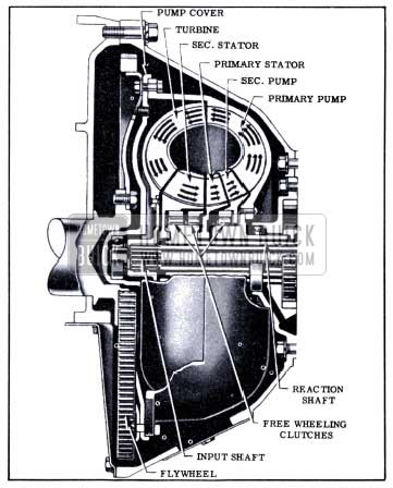
1951 Buick Components of Dynaflow Torque Converter
Torque Converter Pump Assembly
The torque converter pump assembly includes a large primary pump and a much smaller secondary pump.
The primary pump is bolted to the engine flywheel so that it rotates whenever the engine is running. The primary pump and the cover which closes its front end form a housing for all other converter components, and this housing is kept filled with oil.
The primary pump is similar to the impeller of a conventional centrifugal pump but it is shaped so that it discharges fluid in a different direction. A conventional pump impeller picks up fluid at its center and discharges fluid from its rim at approximately 90 degrees to its axis of rotation. Due to the curved form of the blades and the supporting shells, the converter primary pump discharges oil in a direction approximately parallel to its axis of rotation and in the form of a spinning hollow cylinder. See figure 4-43.
The secondary pump is mounted on the hub of primary pump by means of a roller type free wheeling clutch. The free wheeling clutch permits the secondary pump to be locked to the primary pump and be driven when its .action is required, and also permits the secondary pump to free wheel or over-run the primary pump when its action is not required. See figure 4-44.
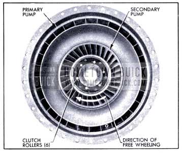
1951 Buick Primary and Secondary Pumps
The blades of the secondary pump are set at a different angle than the entrance ends of the primary pump blades. The secondary pump provides a means of changing the entrance angle of pump blading to conform with changing direction of oil flow into the pump under operating conditions to be described later. Splash and shock losses are eliminated at the pump entrance and maximum pump efficiency is maintained by the operation of the secondary pump.
The function of the converter pump assembly is to convert engine torque into an energy transmitting flow of oil with which to drive the converter turbine, into which the oil is projected from the pump.
Converter Turbine
The turbine is splined to the transmission input shaft through which torque is transmitted to the direct drive clutch and the planetary gears located to rear of the torque converter. The turbine faces the primary pump so that the spinning cylinder of oil projected from the pump enters the turbine at its rim. See figure 4-43.
The curved outer shell which supports the turbine blades causes the oil entering at the rim to flow inward toward the center and be discharged toward the entrance of the pump. See figure 4-43. The entrance ends of the blades curve forward in the direction of pump and turbine rotation so that the spinning oil enters the turbine without splash or shock loss. The exit ends of the blades curve strongly rearward so that the exit oil is discharged in a direction opposite to turbine and pump rotation. See figure 4-45.
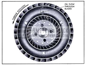
1951 Buick Converter Turbine
The function of the turbine is to absorb energy from the oil projected into it by the pump and to convert the energy into torque with which to drive the rear wheels.
Primary and Secondary Stators
The primary and secondary stators are located between the turbine exit and the pump entrance and are supported on a stationary reaction shaft which is anchored to a flange bolted between the bell housing and transmission case. See figure 4-43.
Each stator is supported by free wheeling clutch rollers and both stators are mounted on a single free wheel race or hub which is splined to the stationary reaction shaft. Each stator can remain stationary or free wheel independently of the other. See figure 4-46.
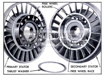
1951 Buick Primary and Secondary Stators
The blades of the two stators together form modified U-shaped surfaces which control the oil flow between turbine exit and pump entrance when the turbine is stationary or at low speed relative to the pump. Oil then leaves the turbine with considerable energy but spins in a direction opposing pump rotation. The stators are stationary and the blades alter the direction of flow so that oil approaches the pump entrance at proper angle to enter without loss of energy and without opposing pump rotation, which would waste an appreciable amount of engine energy.
As the turbine approaches pump speed the direction of oil flow changes until it no longer opposes pump rotation. First the secondary stator, then the primary stator ceases to control oil flow as the direction changes. As each stator ceases to control oil flow it free wheels so that it will not interfere with efficient flow of oil between turbine and pump. Three stages of operation and increased efficiency are obtained by using two stators.
The function of the stators, when stationary, is to change the direction of oil flow from the turbine to the proper angle for smooth entrance into the primary pump, so that all energy remaining in the oil may be utilized to increase pump output.
Operation of 1951 Buick Dynaflow Torque Converter
Operation of the torque converter is the same in Direct Drive, Low and Reverse. The converter transmits torque to the direct drive clutch and planetary gears through the transmission input shaft. The range of transmission operation is determined by control of the clutch and gears as described in paragraph 4-21.
Description of torque converter operation will begin with the car stationary, transmission in Direct Drive, and engine running at idling speeds. At this point the converter pump is slowly turning with the engine and the turbine, directly connected to the rear wheels, is stationary.
Spinning motion imparted to the oil between the rotating primary pump blades produces centrifugal force which causes the oil to flow outward to the pump rim where it is projected into the channels between the turbine blades. Since the entrance ends of the turbine blades are curved forward, as previously explained (subpar. b), the spinning oil enters the turbine without interference or •loss of energy. As the oil flows toward the turbine exit near the center, the backward curvature of the exit ends of the blades reverses the direction of flow. The oil leaves the turbine in a direction parallel to the exit ends of the blades and spinning backward with reference to pump rotation. See figure 4-47.
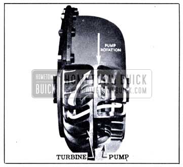
1951 Buick Flow of Oil from the Pump Through the Turbine
The pressure of oil against the stator blades causes the free wheeling clutches to lock and hold the stators stationary. The oil enters the secondary stator nearly parallel to the entrance ends of its blades. The blades change the direction of the backward spinning oil so that it becomes axial flow as the oil leaves to enter the primary stator. The primary stator blades continue to change the direction of flow until the oil has a forward spin that sends it into the pump flowing parallel to the entrance ends of the primary pump blades. The oil pushes against the rear sides of the secondary pump blades, causing this member to free wheel so that the oil can enter the primary pump without interference. See figure 4-48.
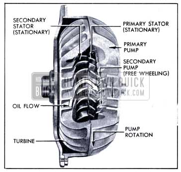
1951 Buick Stationary Stators Changing the Direction of Oil Flow
While the engine is running at idling speeds the oil continues to flow from the pump, through the turbine and stators, and back into the pump in the circuit just described. A gentle circulation is created which does not transmit appreciable torque, although a light movement or creep of car may sometimes be produced.
When the throttle is opened the engine speeds up and rapidly approaches its torque peak. With increased speed, the pump now projects a large volume of oil into the turbine at high rotary speed. The rotating cylindrical mass of oil may be compared to a spinning flywheel rim. A spinning flywheel has stored up energy (turning force) which may be transmitted to any mechanism which opposes its rotation. Since the turbine blades oppose rotation of the spinning flywheel of oil projected from the pump the stored up energy in the oil exerts a powerful impulsion force against the blades, tending to rotate the turbine in the same direction as the pump.
At this stage the impulsion force of the oil against the blades is not sufficient to move the turbine. The oil flows through the turbine channels and is discharged into the stators, which redirect it into the pump entrance. As the oil emerges from the turbine into the stators, spinning at high speed in a reversed direction, it exerts a powerful reaction force against the turbine blades, tending to rotate the turbine in the same direction as the pump.
Engine torque applied to the pump generates a given amount of energy in the oil projected from the pump into the turbine. When the turbine is stationary, the oil passes through the turbine and stators and returns to the pump with almost as much energy as when projected. The amount of energy in the oil thereafter projected from the pump becomes the sum of the energy in returning oil plus the energy resulting from engine torque application, or almost double the amount of energy that could be generated by engine torque alone. The greatly increased energy in the spinning flywheel of oil then projected into the turbine produces a corresponding increase in the impulsion and reaction forces upon the turbine blades.
The described build-up of forces produces a turning force or torque upon the turbine which is much greater than the torque produced by the engine; therefore, torque multiplication is accomplished. It would seem that torque multiplication would increase indefinitely as the cycle repeats itself, but mechanical factors limit the increase in torque multiplication beyond a definite ratio in any given torque converter design.
The design of the 1951 Buick Dynaflow torque converter provides a maximum torque multiplication of approximately 2 1/4 to 1 at stall (car stationary and engine accelerated under load). In combination with the torque characteristics of the Buick engine this provides adequate torque for ail normal starting and driving conditions. Usually the car may be started with appreciably less than the maximum torque multiplication that is available through the converter. For unusually severe• conditions, the Low Range gear may be used to provide an overall torque multiplication of approximately 4.07 to 1 at stall.
Assuming that the increased torque is sufficient to rotate turbine and set car in motion and that acceleration is still demanded by holding the throttle open, the engine picks up speeds, maintaining a fairly large difference in speed between pump and turbine. Transfer of oil from pump to turbine continues in large volume and high torque multiplication exists.
As the car gains speed and momentum the demand for torque decreases so that the applied torque causes the turbine speed to rapidly approach pump speed. As this occurs it is essential for torque multiplication to taper off so that car speed can be maintained at a lower, more economical engine speed. Tapering off occurs automatically because centrifugal force generated in the rapidly rotating mass of oil in the turbine creates an outward counter force which opposes the flow of oil from the pump. Reduction of oil flow and pump output energy effects a decrease in the impulsion and reaction forces upon the turbine so multiplication of engine output torque tapers off as turbine speed increases.
Turbine rotation imparts a forward spinning force to the oil which opposes the backward spinning force with which the oil leaves the turbine. As turbine speed increases and rate of oil flow decreases, the increasing forward spinning force causes the resultant direction of oil flow to swing toward the pump and finally to swing forward in the direction of pump rotation.
When the resultant direction of flow becomes axial (directly toward the pump) the oil pushes against the rearward side of the secondary stator blades, consequently this stator free wheels to prevent interference with the oil flow. The oil still flows in proper direction for smooth entrance into the primary stator blades which continue to effectively redirect oil into the primary pump entrance. See figure 4-49.
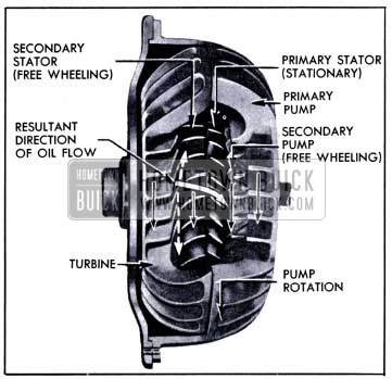
1951 Buick Secondary Stator Free Wheeling and Primary Stator Redirecting Oil Flow
When the resultant direction of oil flow becomes practically parallel to the mean curvature of the primary stator blades the primary stator ceases to redirect oil into the primary pump. At a slightly higher turbine speed the primary stator starts free wheeling. See figure 4-50.
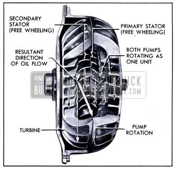
1951 Buick Both Stators Free Wheeling and Both Pumps Rotating as One Unit
When oil is no longer redirected by the stators at an angle which causes free wheeling of the secondary pump, this pump slows down, the clutch locks it to the primary pump hub, and both pumps then operate as one unit. See figure 4-50. Since the oil flowing; toward the pump now has high rotary speed forward, the blades of the secondary pump are set at a proper angle to effectively pick up the oil and assist in energizing it for its next trip around the circuit.
With both stators free wheeling and both pumps operating as one unit the torque converter functions as an efficient fluid coupling, transmitting torque at a 1 to 1 ratio. Sufficient speed differential remains between pump and turbine to enable transfer of oil from pump to turbine, where the oil gives up energy and returns to the pump for recirculation.
The various stages of stator and pump operation described do not occur at set car speeds but are dependent on torque requirements imposed by car operating conditions. With light load and steady driving, torque multiplication may cease at very low car speeds, but with continued acceleration some degree of torque multiplication may be present up to approximately 47 MPH. When the torque converter is operating as a fluid coupling and car operating conditions change so that increased torque is demanded, the converter automatically adjusts itself to meet the demand without any manipulation of controls by the driver.
When the drive through the torque converter is reversed on deceleration or when descending grades, the converter functions as a fluid coupling to permit effective engine braking. It also functions as a fluid coupling when the car is pushed in Low range to crank the engine.
4-21 1951 BUICK DYNAFLOW PLANETARY GEARS AND DIRECT DRIVE CLUTCH
The planetary gears and related parts provide reverse and an emergency low driving range. The direct drive clutch locks the planetary gears to provide direct drive without gear action, when transmission is in Direct Drive (D). In Neutral (N) and Parking (P) the free turning planetary gears and disengaged clutch provide a condition in which the engine is completely disconnected from the propeller shaft and rear wheels.
Although certain parts are common to the planetary gear train and the direct drive clutch, construction details of each system will first be described separately to avoid confusion, then the combined operation of both systems to provide the various ranges will be described.
Construction of Planetary Gears and Related Parts
The gears and related parts which form the planetary gear train are schematically indicated in figure 4-51.
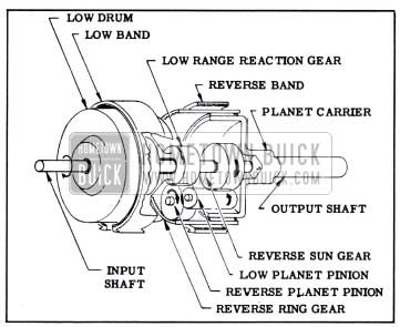
1951 Buick Elements of Planetary Gear Train
The principle elements are as follows:
- Planet carrier
- Three low planet pinions
- Three reverse planet pinions
- Reverse sun gear and input shaft
- Reverse ring gear
- Reverse band
- Low range reaction gear
- High and low drum
- Low band
The parts which control operation of the clutch and the two bands are considered to be part of the hydraulic control system, which is separately described in paragraph 4-22.
The planet carrier, which forms the principle supporting member, is supported in bushings in the transmission case and rear bearing retainer. The transmission output shaft, which is splined to the universal joint, is forged integral with the planet carrier. A bushing in the carrier supports the rear end 6f the input shaft which transmits torque into the gear set from the converter turbine. The three low planet pinions and the three reverse planet pinions are mounted separately on shafts which are anchored at both ends in the planet carrier.
The reverse sun gear, which is the driving gear, is splined to the rear end of input shaft in position to mesh with the three low planet pinions. Each low planet pinion meshes with a reverse planet pinion, functioning as an idler pinion to cause the reverse planet pinion to rotate in the same direction as the sun gear.
The three reverse planet pinions mesh with the internal-toothed reverse ring gear which is supported by the planet carrier. A bushing in the ring gear provides a bearing between the gear and carrier so that each part can rotate independently of the other. The reverse band surrounds the reverse ring gear so that when the band is applied by the hydraulic control mechanism the ring gear will be held stationary. As explained later (subparagraph e), reverse is obtained by holding the ring gear stationary.
The three reverse planet pinions also mesh with the low range reaction gear. The reaction gear is integral with a flange which is keyed to the low drum. The input shaft passes freely through the center of the reaction gear. The low band surrounds the drum so that when the band is applied by the hydraulic control mechanism the drum and reaction gear will be held stationary. As later explained (subparagraph d), low range is obtained by holding the reaction gear stationary.
Construction of Direct Drive Clutch
The direct drive clutch is a hydraulically operated coupling device containing the following parts shown in figure 4-52.
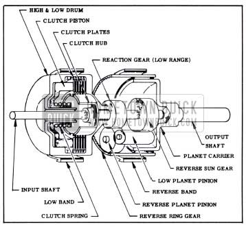
1951 Buick Direct Drive Clutch and Planetary Gears
- Clutch hub
- Five internal splined clutch plates
- Five external splined clutch plates
- Low range reaction gear
- High and low drum
- Clutch piston
- Clutch spring
The clutch hub is splined to the input shaft, which passes freely through the low range reaction gear. The internal splined (faced) clutch plates mesh with splines in the clutch hub so that the plates, hub and input shaft rotate together at all times. The external splined (steel) clutch plates are placed between the internal splined plates and they engage slots in the flange of the reaction gear so that these plates can drive the reaction gear.
The high and low drum and the reaction gear flange form a housing for -the clutch parts, and drum also provides a cylinder for the clutch piston. A neoprene seal located in a groove in piston and a sealing ring located in a groove in the drum hub effectively prevent escape of oil from the chamber formed between the piston and the closed end of drum. Oil may be fed into this chamber through holes in the hub of the drum.
When the transmission is in Direct Drive (D), oil under a pressure of 80-99 psi is fed into the chamber to press the piston against the clutch plates and squeeze them together. This locks the low range reaction gear to the input shaft. In all other ranges oil pressure is not applied and the clutch spring holds the piston away from the clutch plates. The internal and external splined plates are then free of each other and cannot transmit drive to the reaction gear.
Operation of Clutch and Planetary Gears in Direct Drive {D)
In Direct Drive the input shaft and the output shaft (planet carrier) are solidly coupled so that they turn together without any gear action.
Oil pressure supplied through the hydraulic control system applies the direct drive clutch to lock the low range gear to the input shaft. Since the reverse sun gear is also locked (splined) to the input shaft both gears apply equal force to the reverse and low planet pinions, causing these pinions to lock against each other. The driving force is transmitted through the pinions and pinion shafts to the planet carrier so that the output shaft is driven at the same speed and in the same direction as the input shaft. See figure 4-53.
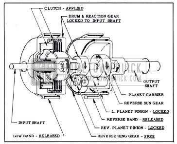
1951 Buick Clutch and Planetary Gears in Direct Drive
Operation of Clutch and Planetary Gears in Low (L)
In Low range the output shaft (planet carrier) turns in the same direction as the input shaft but at a reduced speed.
Oil pressure supplied through the hydraulic control system applies the low band to hold the low drum and the low range reaction gear stationary. The direct drive clutch is disengaged and the reverse band is released.
The reverse sun gear drives the low planet pinions which rotate the reverse planet pinions in the same direction as the input shaft. The reverse planet pinions are meshed with the stationary low range reaction gear; therefore, they move around this gear and exert force through the pinion shafts to rotate the planet carrier and output shaft in the same direction as the input shaft. See figure 4-54.
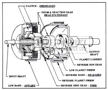
1951 Buick Clutch and Planetary Gears in Low
A speed reduction of 1.82 to 1 in forward motion is obtained in low range planetary gearing. When combined with the maximum torque multiplication of 2.25 to 1 available through the torque converter an overall torque multiplication of 4.07 to 1 is possible, providing is parting torque considerably greater than that obtained with the conventional three speed sliding gear transmission.
Operation of Clutch and Planetary Gears in Reverse (R)
In Reverse the output shaft (planet carrier) turns in a direction opposite to the input shaft, and at a reduced speed.
Oil pressure supplied through the hydraulic control system applies the reverse band to hold the reverse ring gear stationary. The direct drive clutch is disengaged and the low band is released.
The reverse sun gear drives the low planet pinions which rotate the reverse planet pinions in the same direction as the input shaft. The reverse planet pinions are meshed with the stationary reverse ring gear; therefore, they move around inside the ring gear and exert force through the pinion shafts to rotate the planet carrier and output shaft in a direction opposite to the input shaft. See figure 4-55.
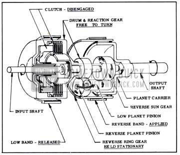
1951 Buick Clutch and Planetary Gears in Reverse
A speed reduction of 1.82 to 1 and reverse motion is obtained in reverse planetary gearing. Combined with the maximum torque multiplication of 2.25 to 1 available through the torque converter an overall starting torque multiplication of 4.07 to 1 is possible in reverse.
Operation of Clutch and Planetary Gears in Neutral (N) and Parking (P)
In Neutral and Parking oil pressure is cut off from the direct drive clutch so that clutch is disengaged. Pressure on both bands is also released. Both the low range reaction gear and the reverse ring gear are free to turn so that the reverse planet pinions cannot react against either gear. The pinions merely rotate without applying force to the pinion shafts; consequently the planet carrier and output shaft remain stationary. See figure 4-56.
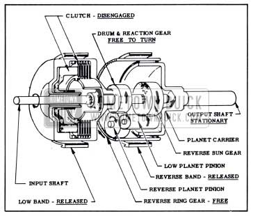
1951 Buick Clutch and Planetary Gears in Neutral and Parking
4-22 1951 BUICK DYNAFLOW HYDRAULIC CONTROL SYSTEM
The 1951 Buick Dynaflow transmission is supplied with sufficient oil to keep the torque converter completely filled when in operation and to provide approximately three additional quarts for lubrication and for operation of all hydraulic controls. Two oil pumps are used to provide oil circulation and pressure and valves are used to regulate and control the oil pressure.
A shift control valve in the transmission routes oil to the controlling devices which govern operation in Direct Drive, Low and Reverse.
In Neutral and Parking positions the control valve cuts off oil pressure to all controlling devices and opens the supply lines for drainage into the sump. The shift control valve is moved into position for the desired range by the driver using the shift control lever on steering column.
The hydraulic control system performs the following functions:
- Keeps the torque converter filled with oil
- Provides lubrication to all working parts
- Applies the clutch in Direct Drive range
- Applies low band in Low range
- Applies reverse band in Reverse range
Oil Pumps
Two oil pumps of the internal gear type are used to provide oil circulation and pressure. The front oil pump, which is driven by the converter primary pump hub, is in operation whenever the engine is running. The rear oil pump, a smaller unit is driven by the transmission output shaft and therefore operates only when the rear wheels are turning.
The front oil pump would be sufficient for all normal operation with engine running. When towing the car for some distance in Neutral’, circulation of oil for transmission lubrication is required. When towing or pushing the car to start the engine oil pressure is required to engage either the low band or the direct drive clutch. Under these conditions the front pump is not operating but the rear pump is driven by the rear wheels to provide the necessary oil circulation and pressure.
The front and rear oil pumps are inter-connected by oil channels provided with check valves so that they can operate together or independently of each other. The arrangement is such that a minimum of power is used in driving the pumps. The conditions under which each pump supplies pressure are described in the following subparagraph.
Oil Pump Pressure Regulation
The pressure of both oil pumps is controlled by the pressure regulator valve which is contained in the same valve body which houses the shift control valve. The cylindrical regulator valve has three lands which control passage of oil through ports in valve body. Two calibrated coil springs press against the inner end of valve, and plugs retain the springs and valve in the body. See figure 4-57.
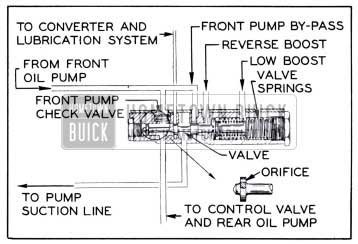
1951 Buick Oil Pump Pressure Regulator Valve
The pressure regulator valve performs the following functions:
- When either pump is running the valve opens the channel port through which oil is fed to the converter and lubrication system, and when neither pump is running the valve closes this port to prevent drainage of oil from converter.
- In Parking, Neutral and Direct Drive the valve regulates pump pressure to 80-90 psi.
- In Low and Reverse the valve regulates pump pressure to 160-180 psi.
When car is stopped and engine is not running the springs hold the valve against its retaining plug so that the second land closes the channel port leading to the torque converter. See figure 4-57.
When the engine is started in Parking or Neutral, oil from the front pump opens the pump delivery check valve and enters the regulator valve cylinder between the first and second lands of the valve. The first land of pressure regulator valve has a small orifice through which oil flows to build up pressure against the outer end of the valve.
When the pressure against outer end of valve becomes sufficient to move the valve against the springs the second land opens the port through which oil is fed to the torque converter and the lubrication system later described in subparagraph c. When the pressure reaches 80-90 psi, the third land of valve opens the front pump bypass port to permit excess oil to return to the pump suction line, thereby controlling the front oil pump pressure to 80-90 psi. See figure 4-61.
After car is in motion in Direct Drive, the rear pump develops sufficient pressure to open the rear pump delivery check valve and the rear pump then delivers oil to the channel between the regulator and control valves as shown in figure 4-62. The increased volume of rear pump causes the regulator valve to move against the springs until the second land permits excess oil to escape into the pump suction line. The combined pressure of both pumps is thereby regulated to 80-90 psi.
As car speed increases the increased output of the rear pump moves the regulator valve farther against the springs to increase the by-pass openings and maintain regulated pressure. As this occurs a greater amount of front pump output is by-passed until at approximately 45 MPH the entire output is by-passed. The front pump delivery check valve closes and from this point the rear pump alone supplies oil at 80-90 psi. See figure 4-62.
In Low the regulations of pump pressure is the same as described for Direct Drive except that the pressure is regulated at 160-180 psi. When in Low range position the shift control valve passes oil into the “Low Boost” chamber which contains the pressure regulator springs. This boosting pressure against the inner end of regulator valve supplements the spring pressure so that higher pump pressure is required to move the valve far enough to open the pump bypass ports. The result is that pump pressure is regulated at 160-180 psi. See figure 4-63.
In Reverse the regulation of front oil pump pressure is the same as described for Direct Drive when starting the car except that the pressure is regulated at 160-180 psi. The shift control valve passes oil into the “Reverse Boost” chamber behind the third land of regulator valve so that the higher pump pressure must be attained before the pump by-pass opens to bleed surplus oil into the pump suction line. Since the rear oil pump is turning in reverse direction it does not supply oil, and the closed delivery check valve prevents drainage through the rear pump. See figure 4-64.
Converter Feed, Oil Cooler and Lubrication Systems
When either oil pump is running, oil flows in limited volume through the converter, oil cooler, and lubrication system.
Oil flows from the pressure regulator valve through a channel containing a restricted metering orifice to limit the volume, and enters the converter around the outside of the reaction shaft and between the primary stator and secondary pump. All parts in the torque converter are lubricated by the oil which completely fills the converter. Oil leaves the converter between the secondary stator and turbine, and flows inside the reaction shaft to a passage in the reaction shaft flange. See figure 4-61.
From the reaction shaft flange the oil is piped to an external oil cooler which maintains the oil temperature at a satisfactory level. The oil cooler is a water could heat exchanger which is supplied with water by the engine cooling system. Oil is piped from the cooler to a passage in the rear bearing retainer which connects with the lubrication system.
A spring loaded lubrication pressure regulator valve is located in the transmission case adjacent to the oil inlet passage in the rear bearing retainer. This regulator valve maintains oil pressure in the lubrication system at approximately 15 psi and by-passes surplus oil to the pump suction line.
The lubrication system provides two lines of oil flow. The front line feeds the high and low drum bushing and all clutch plates. Holes in the clutch hub allows oil to reach all plates. The rear line feeds the transmission case bushing, planetary gears and planet carrier, rear bearing retainer bushing, and the universal joint. See figure 4-61.
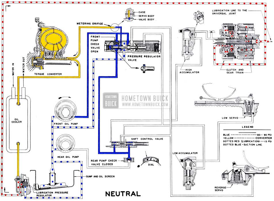
1951 Buick Dynaflow Transmission Oil Flow in Neutral, Showing Converter Feed and Lubrication
Operation of Hydraulic Controls in Neutral and Parking
In Neutral the shift control valve is in the position shown in figure 4-61. In Parking the valve is farther to the right. In both cases the valve blocks passage of oil to the clutch and band controls so that these parts are released and torque cannot be transmitted through the gear train.
In Neutral and Parking there is oil flow through the converter and lubrication system when the engine is running.
Operation of Hydraulic Controls When Shifting Into Direct Drive
As explained in paragraph 4-21, Direct Drive is obtained by applying the direct drive clutch.
When the shift control lever is moved to Direct Drive (D), the control valve is moved into position to pass oil (at 80-90 psi) to apply the direct drive clutch. See figure 4-62.
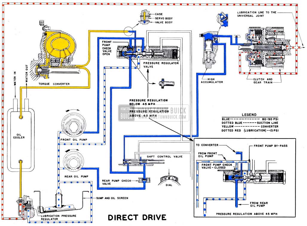
1951 Buick Dynaflow Transmission Oil Flow in Direct Drive
When shifting into Direct Drive a smooth but rapid engagement of the clutch is desired. This is obtained by a cushioning device called a high accumulator, which is inserted in the line between the control valve and the clutch. The accumulator permits a large flow of oil into the clutch apply chamber until clutch engagement just starts and then reduces the flow to prevent sudden, harsh engagement. Its function may be compared to that of a door check.
The high accumulator body contains a large cylinder which houses a piston and heavy coil spring, and the cylinder is closed at the lower end by a cap which has a stop pin to limit the downward travel of the piston against the spring. Lands at both ends of the piston are ground to close fits in the cylinder and the reduced diameter of piston between the lands permits passage of oil between the inlet and outlet ports when the piston is at top of cylinder. The inlet and outlet ports are also connected by a channel containing a check ball. The ball retaining pin fits in an oversize hole which provides a metering orifice for passage of oil between the inlet and outlet ports when the ball is seated to close the larger passage. See figure 4-59.
Before the shift into Direct Drive the piston is held at top of cylinder by the spring. At instant of shift oil passes through the control valve and enters the accumulator, where it flows in large volume around the piston and continues on into the clutch apply chamber. The difference in pressure holds the check ball against its seat so that no oil flows through this channel. See figure 4-58, view A.
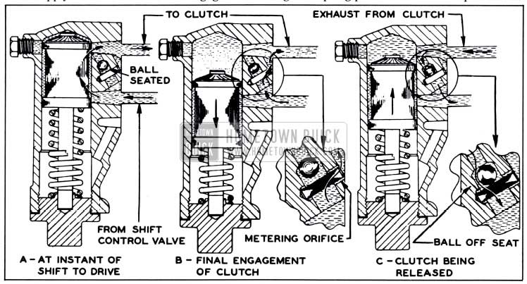
1951 Buick High Accumulator Operation
As soon as clutch apply chamber is filled and clutch engagement begins, back pressure builds up in the accumulator to force the piston down against spring pressure. The rise in pressure as spring is compressed gives smooth final engagement of clutch. The upper land of piston passes the exit port in cylinder as the piston moves down so that passage of oil around the piston is cut off. Oil passing through the metering orifice surrounding the check ball retaining pin then builds up pressure in the accumulator to hold the piston down and to maintain the pressure required in the clutch apply chamber to insure solid engagement of clutch. See figure 4-58, view B.
When oil enters the clutch apply chamber from the high accumulator the clutch piston compresses the clutch spring and presses the clutch plates tightly together. The low range reaction gear is thereby locked to the input shaft and direct drive is obtained as previously described in paragraph 4-21.
Figure 4-62 shows the complete oil flow in 1951 Buick Dynaflow transmission in Direct Drive.
Operation of Hydraulic Controls When Shifting Out of Direct Drive
When shifting out of the Direct Drive in either direction the shift control valve is moved into position to cut off oil pressure to the direct drive clutch and to open the clutch apply line for discharge into the sump. Opening the apply line to atmosphere inside the transmission immediately relieves pressure in clutch apply chamber and the accumulator spring pushes accumulator piston upward to force oil out of accumulator. The reversed flow of oil forces the check ball off its seat so that oil can escape rapidly through that channel. The accumulator piston returns to its original position, and the clutch piston releases the clutch plates. See figure 4-58, view C.
In Reverse and Neutral the drum and piston rotate at much higher speed than the input shaft. High speed rotation would create sufficient centrifugal force in the oil remaining in the clutch apply chamber to partially engage the clutch, this would soon ruin the clutch plates. To insure complete drainage of oil from the clutch apply chamber a check ball bleed valve is placed in the clutch piston. When the clutch is free the check ball is moved off its seat by centrifugal force and residual oil flows out of the apply chamber through the opened bleed hole. When the clutch is engaged in Direct Drive, clutch apply oil pressure forces the bleed valve check ball against its seat to prevent the escape of oil. See figure 4-59.
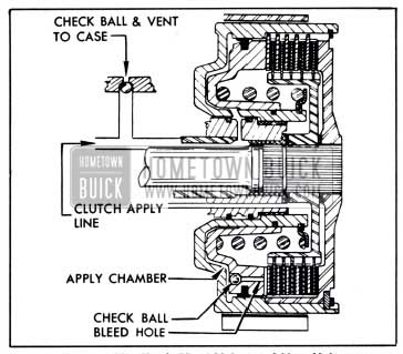
1951 Buick Clutch Bleed Valve and Vent Valve
As oil leaves the apply chamber it creates suction in the apply line. To break this suction a check ball vent valve is placed in the apply line which opens to atmosphere inside the transmission. When apply pressure is directed to the clutch the vent valve is closed by oil pressure to prevent escape of oil. See figure 4-59.
Operation of Hydraulic Controls When Shifting into Low
As explained in paragraph 4-21, Low range is obtained by applying the low band to the low drum so that the attached low range reaction gear is held stationary. When the shift control lever is moved to Low (L), the control valve is moved into position to pass oil to the low servo which applies the low band, also to pass oil to the low boost chamber in the pressure regulator valve body, thereby increasing the apply pressure to 160-180 psi as previously described (subparagraph b) .
The low servo consists of a piston in a cylinder contained in the servo body mounted on bottom of transmission case. Oil entering the cylinder pushes the servo piston upward against the outer end of the band operating lever, causing the band operating lever to pivot and force the strut against one end of the low band. The other end of band butts against another strut which is held by an anchor shaft mounted in the transmission case. The resulting compression of the ends applies the band to the drum so that drum and attached reaction gear is held stationary. See figure 4-63.
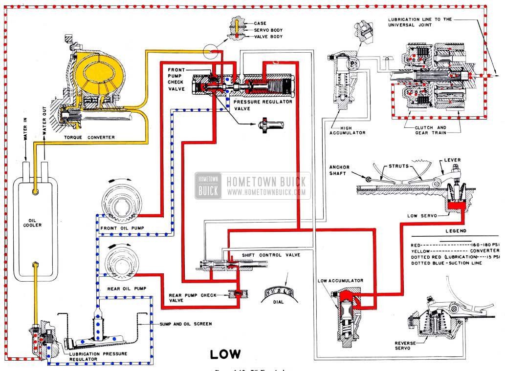
1951 Buick Dynaflow Transmission Oil Flow in Low
When shifting into Low a smooth but rapid engagement of the low band is desired. This is obtained by placing a low accumulator in the low servo oil pressure line. The low accumulator is similar in construction and operation to the high accumulator previously described (subparagraph e), except that a .0625″ metering orifice is drilled in the passage between inlet and outlet ports to control the rate of filling, and a check ball is not used.
Figure 4-63 shows the complete oil flow of the 1951 Buick Dynaflow transmission in Low range.
Operation of Hydraulic Controls When Shifting Out of Low
When shifting out of Low, the shift control valve is moved to shut off oil supply to the low servo apply line and open this line for drainage to the sump. This also relieves the pressure in .the low boost chamber in pressure regulator valve body, therefore the oil pump pressure drops to 80-90 psi.
With pressure relieved, the low servo spring pushes the servo piston down to force oil out of the servo cylinder and release the low band. The accumulator spring returns the accumulator piston to its original position, forcing oil from the low accumulator.
When shifting from Low to Direct Drive under load it is necessary to app.ly the direct drive clutch before the low band is fully released, in order to obtain a smooth transfer of power. All oil discharged from the low servo and low accumulator must pass through the .0625″ metering orifice in accumulator body until the piston upper land reaches the upper port and permits more rapid discharge of oil. The metering orifice controls discharge of oil to retard release of the low band until the direct drive clutch is applied.
Operation of Hydraulic Controls When Shifting Into Reverse
As explained in paragraph 4-21 Reverse is obtained by applying the reverse band to hold the reverse ring gear stationary. When the shift control lever is moved to Reverse (R), the control valve is moved into position to pass oil to the reverse servo which applies the reverse band, also to pass oil to the reverse boost chamber in the pressure regulator valve body thereby increasing the apply pressure to 160-180 psi as previously described (subparagraph b).
Oil at 160-180 psi is applied directly to the reverse servo cylinder and piston in the servo body. The reverse servo piston applies pressure to one end of the reverse band through an operating lever and strut. The other end of band is held by an anchor which is secured to transmission case by the operating lever shaft. See figure 4-64.
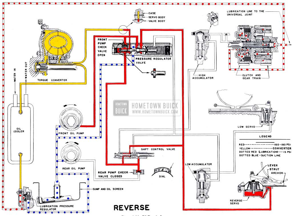
1951 Buick Dynaflow Transmission Oil Flow in Reverse
Oil pressure is supplied by the front pump only. The rear oil pump turns backwards, and the rear pump delivery check valve is held closed to prevent loss of oil through this pump.
Smooth application of the reverse band is obtained through the action of the two-stage reverse servo; an accumulator is not used. Details of the reverse servo are shown in figure 4-60.
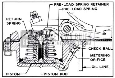
1951 Buick Reverse Servo-Sectional View
The oil line entering the servo cylinder contains a check ball, and a small metering orifice is located to bypass the check ball. The servo piston assembly consists of a piston, pre-load spring and spring retainer assembled on a piston rod and retained by snap rings. The piston is free to move on the rod as it compresses the preload spring until the hub of piston contacts the spring retainer.
When the shift to reverse is made, the resulting oil flow seats the check ball so that oil is fed into the servo cylinder through the metering orifice only. The first movement of the servo piston takes up the clearance between the band and reverse ring gear, then a pressure of approximately 70 pounds is applied to the band operating lever as the piston starts to compress the pre-load spring. Further movement of the piston increases the spring load on operating lever until the reverse ring gear stops spinning. When the piston contacts’ the pre-load spring retainer the full force of oil pressure is solidly applied to the operating l ever to hold the band tightly clamped around the reverse ring gear. The feed through the metering orifice and the cushioning effect of the pre-load spring increases the time of applying the reverse band so that smooth engagement is obtained.
When the shift out of reverse is made, the check ball in apply line is lifted off its seat, permitting a fast discharge of oil from the servo cylinder. The compressed servo piston return spring pushes the servo piston down to effect quick re1ease of the reverse band.
Figure 4-64 shows the complete oil flow in the 1951 Buick Dynaflows transmission in Reverse.
Leave A Comment
You must be logged in to post a comment.