SECTION 11-B 1951 BUICK RADIO
11-6 1951 BUICK RADIO DESCRIPTION AND OPERATING INSTRUCTIONS
The 1951 Buick Sonomatic and Selectronic radio installations consist of a receiver set with built-in speaker mounted at the center of the instrument panel and a 4-section antenna mounted just above the center of windshield. The Selectronic radio installation also includes a foot control switch mounted on the toe panel to left of the brake pedal.
The 1951 Buick radio receiver employs the superheterodyne circuit. The tuner assembly is of the 3-coil iron core permeability-tuned type. The 8-inch speaker is the permanent magnet type.
The 1951 Buick Sonomatic radio receiver has five push buttons for touch-tuning of five pre-selected stations. In addition to the push buttons, a control knob permits manual selection of other stations.
The 1951 Buick Selectronic radio receiver contains an automatic signal-seeking tuner by which the operator can change stations by merely depressing the single selector bar on the receiver, or the foot control switch on the toe panel. The seeking operation is a uni-directional sweep of the broadcast band from low to high frequency with a nearly instantaneous return. The tuning mechanism is driven by a spring loaded mechanical motor which is stopped on station by a triggering circuit actuated by voltage developed from an incoming signal. The number of stations on which the tuner will stop can be regulated by use of the sensitivity control knob on the receiver. In addition to the automatic tuning, a control knob permits manual selection of stations if desired.
All receivers have a terminal post on the output transformer to provide a connection to the rear seat speaker (package 981104) when this is installed on the rear compartment shelf.
1951 Buick Antenna Operation
The antenna position is controlled by a knob located just above the center of windshield inside the body. The antenna may be rotated from the “down” to the “upright” positions by turning control knob; however, the rod extensions must be extended or retracted by hand outside the body.
The antenna is hinged so that it will not ordinarily be damaged when coming in contact with low hanging limbs or other obstructions. The hinge allows the antenna to yield forward or backward, and the antenna returns to its normal position automatically as soon as the obstruction is passed. When entering a garage with a low hanging overhead door, however, the antenna should be turned to “down” position to avoid the possibility of damage when the car is backed out of garage.
Locally strong stations can usually be tuned in with antenna in the down position; locally weak stations will require the antenna to be raised upright and fully extended. To insure adequate sensitivity for selective tuning of the Selectronic radio it is necessary to have antenna in upright position and fully extended.
Switch, Volume, and Tone Control Operation
The switch and volume control knob is to the left of the dial. See figure 11-9. The first portion of rotation clockwise turns on the 1951 Buick radio; further rotation clockwise increases the volume.
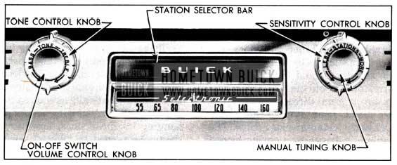
1951 Buick Receiver Controls-Selectronic Radio
The tone control knob is located behind the volume control knob. See figure 11-9. Rotation of tone control knob to extreme “treble” position gives brilliant reproduction of the full tone range. This position will reproduce speech very clearly and distinctly. Rotation counterclockwise toward “bass” diminishes brilliance and accentuates low notes.
When a rear seat speaker is installed, a separate speaker selector switch is mounted on lower edge of instrument panel. The fully counterclockwise position of selector switch knob turns on the rear speaker only, the midway position turns on both speakers, and the fully clockwise positions turns on the front speaker only.
Push Button Tuning Operation – 1951 Buick Sonomatic Radio
To tune in the station for which the push button is set simply push the button in as far as possible. The button will move easily at start, then a slightly harder push is required to complete the travel. At end of button travel the tuner will move to the station for which the button has previously been set as described in paragraph 11-8 (b).
Selective Tuning Operation – 1951 Buick Selectronic Radio
NOTE: To insure adequate sensitivity for selective tuning of the 1951 Buick Selectronic radio it is necessary to have antenna in upright position and fully extended.
With the 1951 Buick radio turned on, selective tuning of available stations is accomplished by depressing either the selector bar above the dial (fig. 11-9), or the foot control switch on toe panel to left of the brake pedal.
When the bar or switch is fully depressed and released the tuner will automatically move to the right and stop, accurately tuned, when it reaches the next station having adequate strength to stop it. The tuner will stop at a station having adequate strength even though the volume control is not turned up high enough for the station to be audible.
When the tuner reaches the right end of the dial it flies back to the left end and again starts moving to the right until it reaches a station having sufficient strength to stop it. By holding the selector bar or foot control switch down, unwanted stations or areas of the dial can be quickly passed over.
The number of stations on which the tuner will stop in selective tuning can be regulated by manual setting of the sensitivity control knob, which is located behind the manual tuning knob to right of the dial. See figure 11-9. This is a step control having six positions. This control is in the circuit only while the tuner is seeking and does not affect the “on station” sensitivity of the receiver.
Turning the sensitivity control knob clockwise, in the direction of arrow marked “MORE,” increases the number of stations that can be tuned in. Turning knob counterclockwise, in direction of arrow marked “LESS,” decreases the number of stations by eliminating those having weak signal strength in the area where car is located. In the extreme “LESS” position of control knob the tuner usually will stop on the strong local stations only.
If the Selectronic tuner is operated in certain localities or in certain types of buildings where a strong signal is not available, the tuner will automatically search the band from one end to the other without stopping until the sensitivity control knob is turned clockwise to include more stations, or until the 1951 Buick radio is turned off.
Manual Tuning Operation
The manual tuning knob is to right of the dial. See figure 1-9. On the Sonomatic radio, this knob may be used to tune in stations other than those for which the push buttons are set; it is also used when tuning to set the buttons for selected stations. On the Selectronic radio, the tuning knob may be used to tune in stations that are too weak to stop the electronic tuning mechanism.
When tuning manually, and particularly when setting up a station on one of the Sonomatic push buttons, careful adjustment of the tuning knob is essential to good radio reception.
On 1951 Buick Sonomatic radio, if the program sounds screechy or distorted, it is probably caused by improper tuning and can be corrected by adjusting the tuning knob slightly. Since the low notes are more affected by tuning than the high ones, it is a good plan to tune the set to a point where the low notes are heard best and high notes are clear but not screechy. Turning the control knob back and forth until the station is almost lost on either side will enable the operator to hear the difference in reception and select an intermediate position giving best results.
11-7 1951 BUICK RADIO TROUBLE DIAGNOSIS ON CAR
The trouble diagnosis information in this paragraph is of a non-technical nature. It is intended as an aid in locating minor faults which can be corrected without a specialized knowledge of radio and without special radio test equipment. If the suggestions given here do not affect a correction, further testing should be done only by a trained 1951 Buick radio technician having proper test equipment.
1951 Buick Radio Is Inoperative or “Dead”
- Turn on the 1951 Buick radio. The dial should light and the vibrator should buzz.
- If dial does not light, disconnect the “A” lead cable and check the fuse located in the receptacle in receiver. If fuse is blown it indicates a sticking vibrator; replace fuse and check vibrator, step 3. If fuse is okay check ”A” lead cable for proper connection to No. 1 terminal of lighting switch and check cable for open circuit. If source of trouble has not been found, remove receiver for test by a trained radio technician.
- If vibrator does not buzz when fuse is okay, remove receiver cover and tap the vibrator. If vibrator starts after tapping, or after installation of a new fuse, let it run for about 15 minutes and then check for any tendency of vibrator to stick by turning radio on and off repeatedly.
Replace the vibrator if it will not start or has a tendency to stick. Replace vibrator if it buzzes unevenly or is exceptionally loud.
- If vibrator buzzes but radio is dead, check the tubes by replacing one at a time until the bad one is located, or test the tubes with a reliable checker if available.
- If fuse, vibrator, and tubes are satisfactory, substitute a test antenna consisting of a piece of wire about 10 feet long connected to a standard antenna lead-in cable. Place test antenna outside and away from the car. If 1951 Buick radio operates near normal with substitute antenna, some part of car antenna or lead-in is at fault.
Lead-in wire may be checked for “grounds” by removing lead-in cable connector from 1951 Buick radio receiver and checking with an ohmmeter from connector tip to car body. This check should show an entirely “open” circuit. CAUTION: Do not check with a lamp or any device drawing current, since the conductor inside loom is only .010″ in diameter and will burn off easily if grounded.
- If source of trouble has not been found remove the receiver for test by a trained radio technician.
1951 Buick Radio Reception Is Weak
- Fully extend the antenna and turn on 1951 Buick radio. Turn volume control to maximum position and tune across the dial.
- If reception seems just slightly weak, tune in a station having good volume for listening and grasp the antenna rod with your hand. If volume increases adjust the antenna trimmer (par. 11-8). If volume decreases proceed with the following steps.
- Check for weak tubes by replacing one at a time until the faulty one is located, or test the tubes with a reliable checker if available.
- If tubes are okay, substitute a test antenna as described in step 5, subparagraph a, above. If this does not reveal source of trouble remove the receiver for test by a trained radio technician.
1951 Buick Radio Noisy with Car Standing Still
- Close and securely latch hood before checking for noise.
- Turn on 1951 Buick radio, start engine, and tune 1951 Buick radio to a spot between stations. Engine noise will usually appear in radio as a clicking sound that varies in frequency with speed of engine. If noise is present disconnect antenna lead-in cable from receiver.
- If engine noise stops when antenna is disconnected, check all high tension wires for full seat in sockets of coil and distributor cap. Check distributor rotor (resistance type) or external suppressor by substituting a known good one. If external suppressor is used it must be installed at distributor end of coil-to-distributor high tension wire. Do not use a suppressor and a resistance type distributor rotor together.
- If distributor rotor or suppressor does not correct the noise, check antenna lead-in cable shield for proper ground (par. 11-9, c).
- If engine noise continues with antenna disconnected, check ignition coil and generator capacitors for clean, tight connections; also check the bond strap on the water temperature gauge tube to make sure it has a clean tight connection to cowl. Remove generator cover band and observe sparking; if sparking is excessive, check for open armature.
- If source of noise has not been found, replace ignition coil and generator capacitors with known good ones. Ignition coil capacitor lead must be attached to battery terminal of coil. Generator capacitor lead must be connected to “A” terminal of generator. Both capacitors must have clean metal ground contact.
- If engine noise is present when engine is running at approximately 2000 RPM, and all items mentioned above are satisfactory, the noise is probably due to the generator regulator. Correction may be made by mounting a .33 mfd capacitor at one of the regulator mounting ground screws and attaching the capacitor lead to the “BAT” terminal of regulator.
1951 Buick Radio Noisy with Car Moving at High Speed
- Turn on 1951 Buick radio and check for engine noise as described in subparagraph c above. If engine noise is present, correct as outlined.
- Drive over different types of roads, especially macadam, with 1951 Buick radio on and tuned between stations. Listen for presence of wheel or tire static. In mild form this static shows up as a click in radio that increases with speed; when more severe it shows up as heavy static or a constant roar. The surface of the road determines the strength of static discharge. Wheel or tire static very seldom occurs on dirt or gravel roads.
- If wheel or tire static is present, apply brakes lightly and if noise decreases check front wheels to see that static collectors have been properly installed and make sure that all grease has been wiped off contacts.
- In certain cases of wheel or tire static, the front wheel static collectors alone may not completely eliminate all noise from this source.
Static Eliminator Powder, available through G.M.P.D. parts warehouses under Group 9.674, may be used in cases where proper conditioning of static collectors does not remedy tire static. An injector for installing the powder is also available under the same group number. This powder equalizes the positive and negative charges developed by the tire, thus neutralizing the corona effect and eliminating radio interference difficulties from this source.
1951 Buick Radio Noisy on Rough Road
- Turn on 1951 Buick radio and check for engine noise as described in subparagraph c above. If engine noise is present, correct as outlined.
- Jar the receiver by striking the case with heel of hand, or a rubber mallet. If this produces noisy reception, remove receiver cover and tap each tube with handle of screwdriver until noisy tube is found. Make sure that all tubes are firmly pressed into sockets. If this does not correct the noise, remove receiver for test by a trained radio technician.
- If noisy reception is not produced when receiver is jarred, fully extend antenna and turn radio volume control on full. If noise appears in speaker check antenna and lead-in wire for loose connections. If wiggling lead-in does not cause noise, rap antenna rod with insulated end of screwdriver; if noise then appears, check antenna for shorting to car body or corrosion between antenna sections.
11-8 1951 BUICK RADIO ADJUSTMENTS-ON CAR
When making the adjustments covered in this paragraph it is essential to have the car in a location that is as free as possible from outside interference.
Antenna Trimmer Adjustment
An antenna trimmer adjustment is provided for matching the antenna coil in the receiver to the car antenna. This adjustment must always be made after installation of receiver and antenna, or after any repairs to these units. The adjustment should also be checked whenever the 1951 Buick radio reception is unsatisfactory.
- Raise antenna to maximum height.
- Tune radio to a station between 1300 and 1500 K.C. that can barely be heard with volume turned full on.
- Insert a screwdriver through the opening in receiver cover labeled “Antenna Trimmer Adjustment” and carefully turn the trimmer screw back and forth until a position is found that gives maximum volume.
Setting Push Buttons to Desired Stations – 1951 Buick Sonomatic Radio
- Turn on the 1951 Buick radio.
- Pull button to left and all the way out.
- Carefully tune in the desired station manually (par. 11-6, e), then push the button all the way in.
- Move dial pointer away from the selected station and push the button to make certain the station will be properly tuned in. Turn tuning knob back and forth to make certain that best tuning is obtained with the push button.
11-9 1951 BUICK RADIO INSTALLATION INSTRUCTIONS
If radio parts are removed from car for any reason, the instructions contained in this paragraph must be carefully followed to insure proper reinstallation and satisfactory operation of the radio.
Whenever the receiver is being removed from a car equipped with a rear seat speaker, it is advisable to first remove the speaker selector switch from its mounting bracket to avoid straining the wire connections at the switch. Remove receiver, then remove back cover and disconnect switch wires from receiver.
Installation of 1951 Buick Receiver
- The radio hangers must be bolted to the radio support brackets with slot openings toward front of car.
- Thoroughly clean surface around mounting holes in speaker grille to insure a good electrical connection with the receiver.
- If rear seat speaker is used, remove back cover of receiver and insert the two-wire cable from the speaker selector switch through a vent hole in bottom of receiver, pushing the rubber grommet into place in vent hole. Connect wires to the receiver and reinstall receiver cover.
CAUTION: Carefully support receiver until it is installed, to avoid straining the wire connections to speaker selector switch.
- Install receiver by sitting in front seat holding receiver at arm’s length while the two threaded bushings are inserted through control holes in speaker grille and the studs on side of receiver are engaged in the extended lip on the hangers.
- Install and tighten hex nuts on threaded bushings. Hold receiver so that rubber gasket at speaker opening touches the back of speaker grille, then install large flat washers, lockwashers and nuts on receiver studs and tighten nuts securely.
- Install tone control knob, felt washer, and volume control knob on shaft to left of the dial. Install dummy knob (Sonomatic) or sensitivity control knob (Selectronic), felt washer, and tuning control knob on shaft to right of the dial. See figure 11-9.
To install outer knobs simply push them on shafts as far as possible. To remove either knob, insert a small screwdriver in slot on edge of knob and pry against the flat spring located inside the knob.
- Reinstall rear seat speaker selector switch if removed from mounting bracket.
- Connect the “A” lead cable to one of the No. 1 (unprotected) terminals of lighting switch. Never connect to any other terminal. Install 15 ampere fuse in receptacle in receiver and connect lead to socket in receiver toward left side of car.
- Connect antenna lead-in wire and foot control cable (Selectronic only) to receiver, then make antenna trimmer adjustment (par. 11-8). CAUTION: Make certain that leads do not contact windshield wiper drive cables when wiper is running.
Installation of Selectronic Foot Control Switch
- Fold back left side of floor mat and insulation to expose pedal plate below steering column.
- Locate and drill switch mounting holes in pedal plate using template furnished, then install control switch on pedal plate with screws.
CAUTION: Templates are different for Synchromesh and Dynaflow cars-be sure to use correct template.
- Lead the control switch cable up behind left edge of steering column pad and support it in wiring harness clips on rear side of cowl. Plug cable into receiver and attach it to clip on receiver cover. See figure 11-10. CAUTION: Make certain that cable does not contact windshield wiper drive cables when wiper is running.
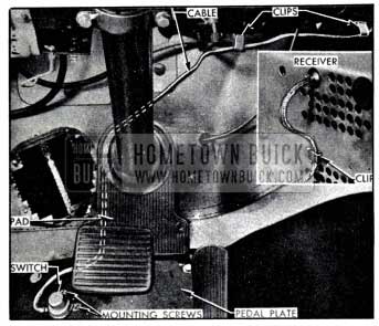
1951 Buick Foot Control Switch Installation
Installation of 1951 Buick Radio Antenna – Closed Bodies and Model 45R
IMPORTANT: The standard Buick antenna is matched with the receiver within the range of the trimmer adjustment. Other antennas may not match the receiver within the range of the trimmer adjustment; therefore the use of other than a standard Buick antenna is not recommended.
- Apply masking tape to area of roof panel where antenna control is to be installed, also to instrument panel along the right windshield garnish molding. This will prevent damage to car finish.
- Remove right section of windshield garnish molding.
- Push headlining up against header reinforcement above center of windshield so that hole in reinforcement can be felt. Cut two slits in headlining at right angles to each other, across the hole in reinforcement.
- The antenna package contains a drill guide having a 1/8″ center hole and a smaller hole to one side. Attach a cord through the smaller hole so that guide can be retrieved if accidentally dropped inside the header reinforcement.
- Insert drill guide through hole in header reinforcement and seat it in square hole in the header inner frame. Drill a 1/8″ hole through the roof panel.
- Use the %” hole to pilot a 1 1/8″ circular cutter and cut hole through roof panel while holding cutter at 90° to windshield glass. See figure 11-11. Remove masking tape from roof panel.
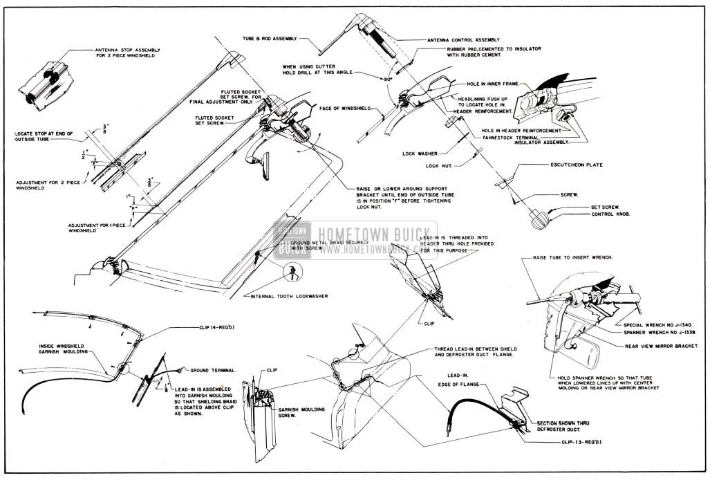
1951 Buick Antenna Installation Details-Closed Bodies and Model 45R
NOTE: If there is any doubt of the location of the Fahnestock terminal the lead-in wire should be checked for “grounds” with an ohmmeter. It should, of course, show an entirely “open circuit.” Do not check with a lamp or any device drawing current as the conductor inside of the loom is only .010″ in diameter and will burn off easily if grounded. For the same reason, care should be taken to see that the bare terminal on the end of the plug does not touch any “hot” terminal behind the instrument panel.
- Install antenna escutcheon plate, threading screws into holes provided in header reinforcement. Install knob and tighten set screw securely.
- On two-piece windshield job, install antenna stop on windshield division molding in location shown in figure 11-11, and tighten screws evenly.
- If antenna rod does not snap into antenna stop easily (2-piece windshield), or is not correct distance from windshield glass (1-piece windshield), the fluted socket set screw can be turned in against the polished ring to make a small adjustment of the antenna rod. This adjustment should be used only for a very slight change.
- Connect lead-in cable to receiver and make the trimmer adjustment described in paragraph 11-8.
Installation of 1951 Buick Radio Antenna – Convertible and Riviera Bodies
Installation details are clearly shown in figure 11-12.
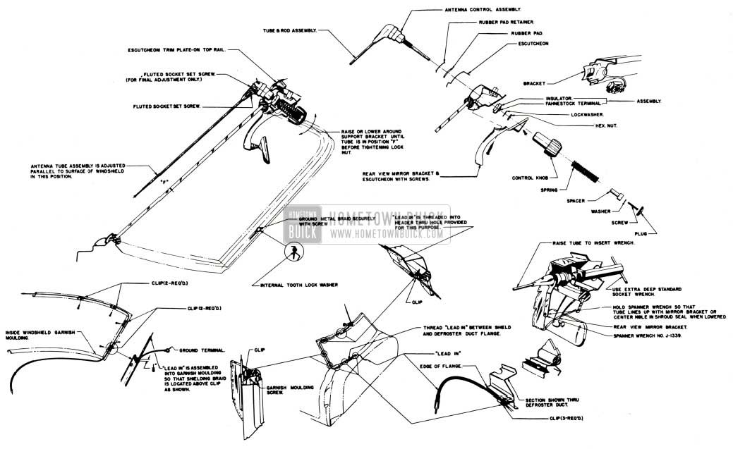
1951 Buick Antenna Installation Details-Convertible and Riviera Bodies
The installation procedure is very similar to that on closed bodies (subpar. c, above) except for the following points:
- The insulator is installed with the Fahnestock terminal toward right side of body.
- A rubber pad retainer, rubber pad, and escutcheon are used on outside of header.
- The inside escutcheon is integral with the rear view mirror bracket.
- The control knob is installed with a spring, spacer, washer, screw, and plug.
- Antenna rod is set parallel to windshield glass at center.
Installation of Interference Suppression Parts
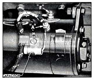
1951 Buick Capacitor Mounted on Generator
Figure 11-13 shows proper installation of the capacitor to prevent interference caused by the generator. Note that capacitor lead is connected to the armature (“A”) terminal of generator. Capacitor must never be connected to the field (“F”) terminal as this will cause bad pitting of the voltage regulator points, thus preventing it from operating properly.
First production jobs use an external distributor suppressor which must be securely attached to distributor end of high tension wire from coil. Later production jobs use a resistance type distributor rotor, which can also be used instead of the suppressor on first jobs. Do not use both the suppressor and rotor on any installation.
The coil capacitor is mounted on the coil bracket and the lead is connected to the battery (+) terminal of coil. See figure 11-14.
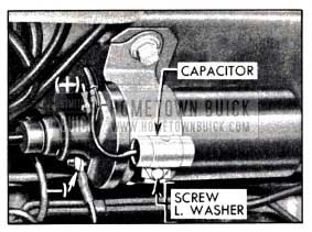
1951 Buick Capacitor Mounted on Coil
If capacitor is connected to the distributor (-) terminal excessive pitting of distributor contact points will result.
A static collector is installed in each front wheel hub grease cap. For good results the grease cap and the center of steering knuckle spindle must be clean and free from grease. The center of static collector is made of self-lubricating material.
In addition to the items mentioned above, a bond strap is attached to the temperature gauge tube. This strap must have a clean tight connection to the dash.
Reinstallation of Rear Seat Speaker (Package 9811 04)
If rear seat speaker is removed for any reason, be sure to reinstall the speaker, rubber gasket, grille screen, and bezel as shown in figure 11-15.
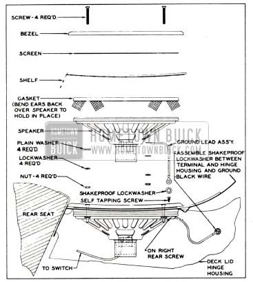
1951 Buick Rear Seat Speaker Installation
Place one terminal of the black ground wire under the right rear speaker mounting nut. The other end of ground wire is attached to the right trunk lid hinge guard with a screw and a shake proof washer placed between terminal and hinge guard.
11-10 1951 BUICK RADIO ALIGNMENT PROCEDURE
Under no circumstance should alignment be attempted without calibrated test oscillator and output meter, or by untrained personnel.
These alignment instructions must be rigidly adhered to and all adjustments must be made in the order given.
Alignment Preliminaries
The 1951 Buick radio receiver should be functioning before the various aligning adjustments are made. Trouble shooting, if necessary, should precede the final adjustment. Receiving signals at correct dial setting depends upon having the proper relation between tuning condenser and the dial scale. Pointer or dial setting is necessary because the scales are not linear with frequency and all scales are precalibrated for maximum accuracy.
Superheterodyne Theory and Alignment
Buick Sonomatic Auto Radios employ the superheterodyne circuit which uses an intermediate frequency (I-F) amplifier, the characteristics of which largely govern the selectivity of the receiver. The I-F amplifier characteristics are determined principally by the adjustment and design of the I-F transformers. It is, therefore, important that the I-F amplifier be correctly adjusted to provide the best selectivity. These adjustments are in the form of iron cores placed within the coils. During alignment it is necessary only to adjust these iron cores as specified in the tabulated alignment procedure, to obtain best operation. Incorporated in every superheterodyne is a local oscillator, the output of which mixes with the incoming signal from the antenna. The local oscillator does not operate at the same frequency as the incoming signal which is to be received. The resonant (acceptance) frequency of the I-F amplifier establishes the difference in frequency required; 260 K.C. is used on Buick radios. The local oscillator operates at a frequency higher than the incoming signal, the two predominating resultant frequencies produced are the sum and the difference of the two frequencies. The design of these receivers is such that the difference in frequency is the same as the I-F amplifier resonant frequency. Modulation of the incoming signal will be present as modulation of input to the I-F amplifier.
Effects of R-F or I-F Misalignment
The effects of misaligned R-F or I-F stages are most commonly observed as a loss of sensitivity either over a portion or over entire band; loss of sensitivity, often characterized by the selectivity being noticeably unequal on the two sides of the point of best reception; change in fidelity; and inaccurate dial readings. Loss of fidelity will be apparent as a loss of high or low audio frequencies. If the I-F amplifier is not tuned to the specified frequency, the oscillator and other tuned circuits will not track. The dial readings will then be incorrect and a portion of the band will have low sensitivity.
Test Oscillator Connections – Dummy Antenna Use
The chassis or frame of the 1951 Buick radio receiver is considered as being at ground potential and the “0” or “GND” terminal of the test oscillator should be connected to the chassis wherever good contact can be established. The “ANT” or “HIGH” terminal of the Test Oscillator output must be connected to the antenna connector or other points in the radio receiver as specified in “Tabulated Alignment Specifications” (subpar. g or h). The use of a fixed condenser in series with the test oscillator lead is specified in some instances. A .1 mfd. condenser is used in aligning the 1-F stages and a 0.000082 rnfd. condenser is used in series with the antenna connector. This condenser, sometimes called “Dummy Antenna,” provides a proper input loading to the receiver. It is important that this condenser be connected at the point where the Test Oscillator lead joins the 1951 Buick radio set, and should not be connected at the test oscillator. Shielded leads should be used.
Output Meter Connections
Any standard type of output meter can be employed during alignment. The meter should be connected across the secondary of the output transformer. It is best to leave the voice coil connected while using the output meter. It is essential that an output meter with sufficient sensitivity be used to avoid the possibility of using too much Test Oscillator output to get a readable indication on the output meter. Sometimes it is desirable to connect the output meter from plate to plate of output tubes; when this connection is employed be sure that a .1 mfd. condenser is connected in series with the meter to afford protection from the d-e potential.
Alignment of the Tuned Circuits
Tuning adjustment with trimmers or adjustable iron cores is accomplished while applying a modulated signal, of the specified frequency to the input of the stage being adjusted. Maximum Output Meter indication, of the amplitude of Audio-Frequency output, of the 1951 Buick radio receiver, shows when tuning is correct. The various tuned circuits are aligned by adjusting each in this manner. During all alignment adjustment, the output of the Test Oscillator must be kept as low as possible, consistent with a reasonable output meter indication, to prevent A-V-C action from taking place and making all adjustments seem very broad.
The tuning tool used must have a minimum of metal so it will cause little or no tuning reaction. If removing the tool, after making an adjustment, reduces the output appreciably, a slight compensating mistuning will correct the error and produce maximum output when the tool is removed.
Tabulated Alignment Specifications
The tabulated alignment specifications on page 11-18 apply only to the 1951 Buick radio models indicated. See figure 11-17 (Sonomatic) or 11-18 (Selectronic) for location of the adjustment screws indicated in the specifications.
NOTE: When aligning the Selectronic radio be sure to use a vacuum tube voltmeter as indicated and be sure to follow the alignment sequence given-(Notice that the primary of the 2nd I.F. is aligned first).
TABULATED ALIGNMENT SPECIFICATIONS-SONOMATIC, MODEL NO. 980979
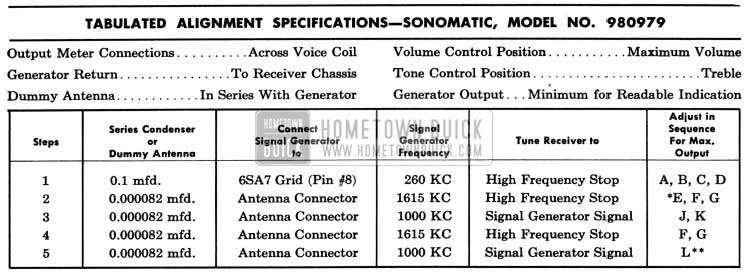
1951 Buick Sonomatic Radio Alignment Specifications
*Before making this adjustment check mechanical setting of oscillator core “H.” The rear of the core should be 12%2″ from the mounting end of the coil form. (This measurement is readily made by inserting a suitable plug in the mounting end of the coil form.) Core adjustments should be made with an insulated screw driver, and core studs should be cemented in place with glyptal or household cement after alignment.
**Lis the pointer adjustment screw which is on the connecting link, between the pointer assembly and the parallel guide bar. It should be adjusted so that the dial pointer corresponds with the 1000 KC mark on the dial. (On first ”0″ of “100.”)
With the 1951 Buick radio installed and the car antenna plugged in adjust the antenna trimmer “G” for maximum volume with the radio tuned to a weak station near 1400 KC (see sticker on case).
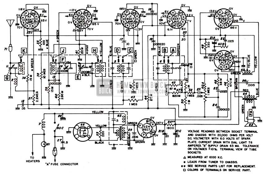
1951 Buick Radio Circuit Schematic-Sonomatic Radio
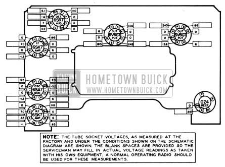
1951 Buick Tube Socket Voltages-Sonomatic Radio
TABULATED ALIGNMENT SPECIFICATIONS-SELECTRONIC, MODEL NO. 980980
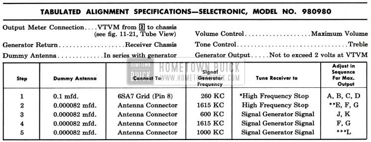
1951 Buick Selectronic Radio Alignment Specifications
*To tune to high frequency, put a 0.070″ feeler gauge (or bare #13 wire) in slot against the high frequency stop. Depress station selector bar and allow the planetary arm to run against the feeler gauge. Turn the radio off and then back on.
**Before making this adjustment, check the setting of oscillator core “H.” The rear of the core should be 1 25/32″ from the mounting end of the coil form. This measurement is readily made by inserting a suitable plug in the mounting end of the coil form. The core adjustment is made from the mounting end of the coil form with an insulated screwdriver. (It will be necessary to steady the core guide bar while making these adjustments. This can be done by applying a downward pressure on the guide bar at the antenna coil end.) If this adjustment is necessary, first dissolve the glyptal seal on the core stud and be sure to re-seal after making the adjustment.
***”L” is the pointer adjustment screw on the end of the core guide bar-adjust so pointer reads 1000 KC.
With the radio installed and the antenna plugged in, adjust the antenna trimmer “G” for maximum volume with the radio tuned to a weak station near 1400 KC (see sticker on case.)
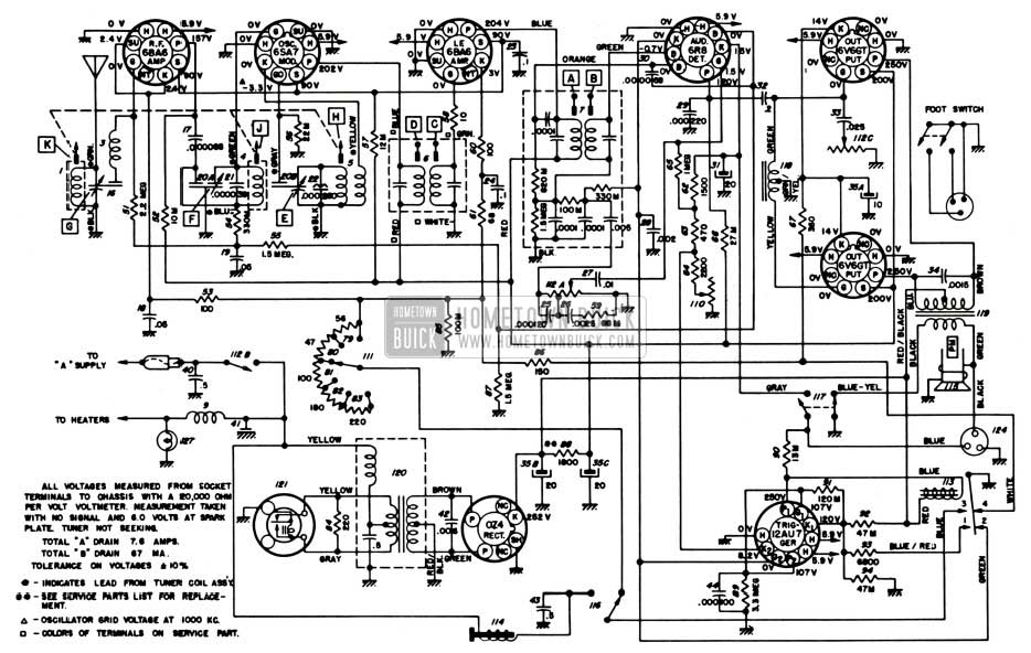
1951 Buick Radio Circuit Schematic-Selectronic Radio
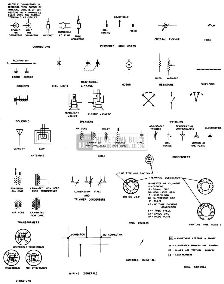
1951 Buick Radio Circuit Legend
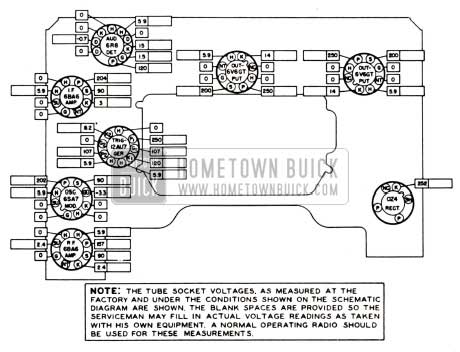
1951 Buick Tube Socket Voltages-Selectronic Radio
11-11 1951 BUICK SONOMATIC RADIO SERVICE PARTS LIST
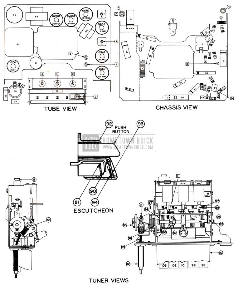
See figure 11-21 for Illustration Numbers indicated in the following parts list.
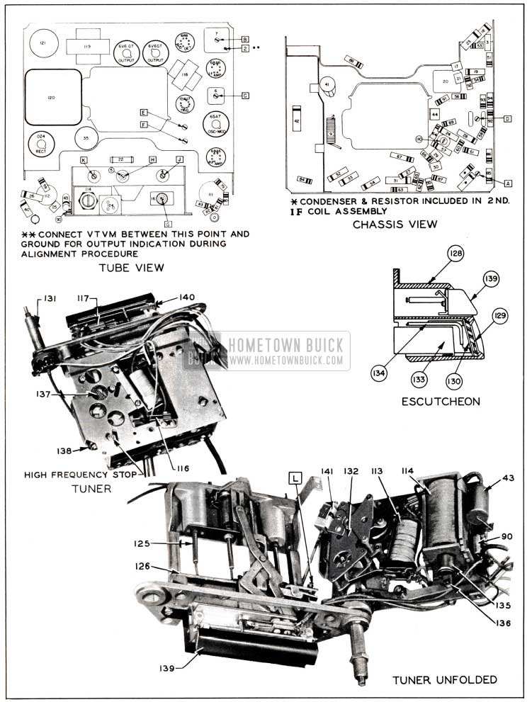
1951 Buick Parts Layout-Sonomatic Radio
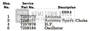
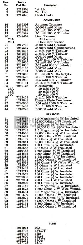
1951 Buick Radio – Electrical Parts
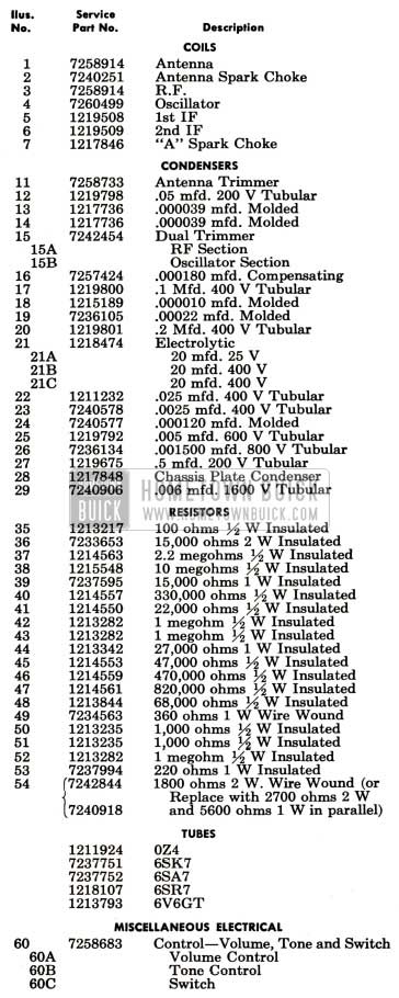
1951 Buick Sonomatic Radio Electrical Parts
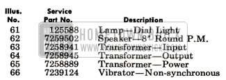
1951 Buick Sonomatic Radio Electrical Parts Overview
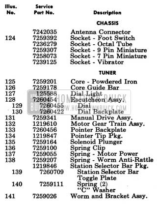
1951 Buick Radio – Mechanical Parts
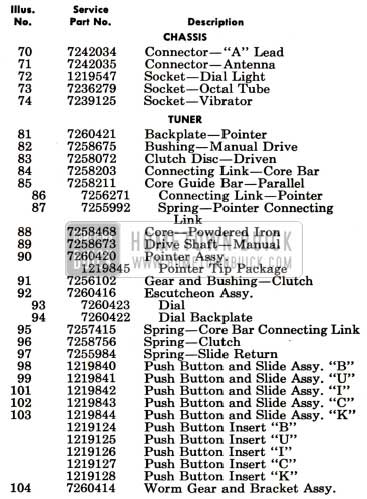
1951 Buick Sonomatic Radio Mechanical Parts
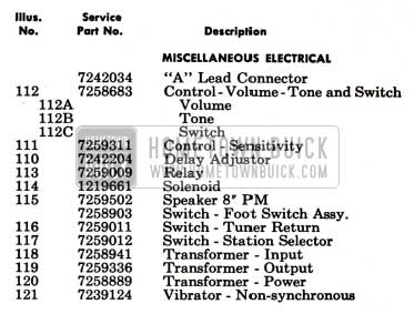
1951 Buick Radio – Installation Parts
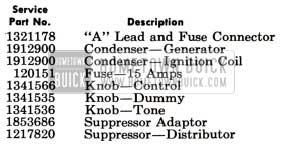
1951 Buick Sonomatic Radio Installation Parts
11-12 1951 BUICK SELECTRONIC RADIO SERVICE PARTS LIST
See figure 11-22 for Illustration Numbers indicated in the following parts list.
1951 Buick Parts Layout-Selectronic Radio
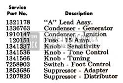
1951 Buick Radio – Electrical Parts
1951 Buick Selectronic Radio Electrical Parts
1951 Buick Selectronic Radio Electrical Parts Overview
1951 Buick Selectronic Radio Electrical Parts View
1951 Buick Radio – Mechanical Parts
1951 Buick Selectronic Radio Mechanical Parts
1951 Buick Radio – Installation Parts
1951 Buick Selectronic Radio Installation Parts
Leave A Comment
You must be logged in to post a comment.