SECTION 13-C 1951 BUICK WINDSHIELD WIPERS – CLOSED BODY WINDSHIELD, WINDOW GLASSES AND VENTILATORS
13-10 WINDSHIELD WIPERS
Description of 1951 Buick Windshield Wiper
On Series 40, the windshield wiper motor is mounted under the cowl and is connected to the two windshield wiper transmissions by flat steel links.
On Series 50-70, the windshield wiper motor is mounted on an auxiliary drive which is attached to the front face of the cowl panel, under the hood. The motor drives a short shaft in the auxiliary drive which extends through the cowl panel. A cross lever on rear end of the auxiliary shaft actuates the wiper transmissions through cables attached to the lever and to pulleys in the transmissions. The cables run around pulleys on cable tensioners mounted under the cowl. Each cable tensioner has a spring and ratchet which automatically take up slack and maintain proper tension on the cables.
CAUTION: 1951 Buick Windshield wiper arms must not be rotated by hand for any reason as this places an undue strain on the cable fasteners.
The tube which connects the wiper motor to engine intake manifold is attached to a valve on the motor. The motor valve is actuated by a bowden cable extending from a control mounted on left end of instrument panel. The 1951 Buick windshield wiper is operated, with engine running, by turning control knob clockwise. When car is equipped with a windshield washer the wiper control contains a button to control washer operation as described in paragraph 11-2.
Correction of Sluggish Windshield Wiper Motor
If 1951 Buick windshield wiper motor is sluggish or lacking in power first make certain that the vacuum pump is operating properly and all hose connections are tight, as outlined in paragraph 3-16. If windshield wiper motor is found to be at fault, check and lubricate the motor as follows:
- Remove valve cover and gasket, then lift out the kidney valve with needle nose pliers. See figure 13-11. NOTE: Wiper motor must be removed from car on Series 40 only.
- Check distance that kidney valve tube protrudes from valve body. If distance is greater than 1/8″, press tube into valve body to this dimension. See figure 13-13.
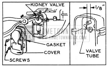
1951 Buick Removing Kidney Valve and Checking Tube
- The kidney valve tube must be a snug fit in valve body. If kidney valve tube is loose enough to be jiggled with fingers after being set to specified dimension the wiper motor should be replaced.
- Wipe all dirt and lubricant from surfaces of kidney valve, valve body behind valve, and valve cover.
- Apply a thin coating of “Trico WiperLube” to face of kidney valve that contacts the valve body. This lubricant is available at UMS Service Stations.
- Install kidney valve, gasket and cover. Install wiper motor if removed from car. Check wiper motor operation.
Replacement of 1951 Buick Windshield Wiper Control
- Loosen clamp screw and disconnect control cable from valve on windshield wiper motor.
- On Series 50-70 only, disconnect battery ground cable, then remove fuse block from instrument panel.
- Carefully pry control knob rearward to remove it from control valve shaft, to which it is retained by a small spring.
- Using special socket wrench shown in figure 13-14 remove control nut and internal-tooth lockwasher then remove control from instrument panel. Disconnect windshield washer hoses if attached to control.
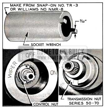
1951 Buick Control and Transmission Nut Socket Wrench
- When reversing above procedure to install the control, adjust the control cable at clamp screw on wiper motor so that valve is fully opened when control knob is at “ON” position. On Series 50-70, install fuse block then connect battery ground cable in proper manner to wind the clock (par. 10-66).
Series 40 Windshield Wiper Transmission Removal and Installation
- Remove wiper blade and arm from transmission shaft.
- Remove defroster hose, glove box and defroster housing as required to reach the 1951 Buick windshield wiper motor and the transmission to be removed.
- Disconnect transmission link at wiper motor. The spring connected washers of the link retainer have key hole slots for engagement with grooves in link pins on wiper motor lever.
- Disconnect windshield washer hose from transmission.
- Remove bolt and retainer which anchor the transmission on underside of cowl, then remove transmission and gasket from outside of body, threading the attached link up through hole in cowl.
- When transmission is installed by reversing the procedure for removal, seal the gasket with 3-M Autobody Sealer but use care to keep sealer away from windshield washer hose connection. Connect the right transmission link to the upper pin and the left link to lower pin on the wiper motor lever.
- Before installing wiper arm and blade, operate the windshield wiper and then stop it to obtain the proper parked position. Install arm and blade so that blade just clears windshield glass rubber channel in parked position.
Series 50-70 Windshield Wiper Transmission Removal and Installation
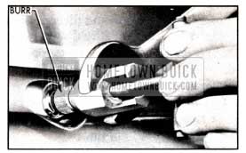
- Remove wiper blade and arm from driving burr on wiper transmission shaft.
- Remove adapter screw from handle of Burr Remover and Replacer J 2682 and thread in into the end of transmission shaft, then install the tool so that clutch end of barrel grips the underside of driving burr. Hold the barrel of tool stationary with an open end wrench, turn handle of tool counterclockwise until burr is removed. See figure 13-15.
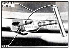
1951 Buick Removing Driving Burr from Transmission Shaft
- Remove transmission nut using special socket wrench shown in figure 13-14. Remove 1951 Buick windshield washer nut and nozzle, then remove escutcheon.
- Working under instrument panel, disconnect windshield washer hose. For removal of right hand transmission also remove the glove box.
- Apply slight pressure to cable tensioner ratchet spring, then rotate pulley support plate until a 1/8″ pin can be inserted through the holes in plate and bracket to remove spring pressure from the cables. See figure 13-16. Disconnect cables from drive shaft lever.
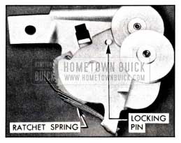
1951 Buick Cable Tensioner
- Remove two attaching bolts and lower the transmission out of position and remove.
- Install 1951 Buick windshield wiper transmission by reversing procedure for removal, observing the following points:
- Before installing transmission coat the shaft with liquid soap to aid in inserting it through the 1951 Buick windshield glass channel.
- When connecting the transmission cables to drive shaft lever, attach the right hand end of cable to upper end of drive shaft lever, and attach left hand end to lower end of lever. Pass the right hand loop of cable over the upper pulley on cable tensioner and pass the left hand loop over the lower pulley.
- While holding cables in pulleys, apply slight pressure to cable tensioner ratchet spring and rotate pulley support plate to remove pressure from temporary locking pin which will then fall out of holes. Slowly release pulley support plate until cables are tight, then release ratchet spring. CAUTION: Do not let pulleys snap against cables.
- Before installation of escutcheon and nut apply 3-M Autobody Sealer around base of wiper shaft and washer outlet.
- Always install a new driving burr on upper end of transmission shaft and use Remover and Replacer J 2682 to press it into position. The bore of a new burr is not serrated; the splined shaft cuts serrations in the softer metal of burr during installation.
- Reverse the barrel on handle of tool J 2682 so that tapered end of barrel is toward threaded pilot of handle. Carefully place new driving burr on shaft so that it is squarely aligned, then screw the threaded pilot of tool handle into end of transmission shaft.
- Holding handle of tool stationary, carefully and gradually turn the barrel counterclockwise with an open end wrench until the driving burr has been pressed flush with end of shaft. See figure 13-17.
1951 Buick Installing Driving Burr on Transmission Shaft
- Before installing wiper arm and blade, operate the 1951 Buick windshield wiper and then stop it to obtain the proper parked position. Install arm and blade so that blade just clears windshield glass rubber channel in parked position.
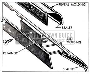
13-11 BELT, HEADER, AND REVEAL MOLDINGS
IMPORTANT: Belt, header, and reveal moldings must not be pried loose as they are retained by clips and bolt type retainers.
This paragraph contains replacement information on the various types of external moldings at 1951 Buick windshield and window openings.
Replacement of Front End Belt Molding
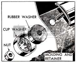
The Series 40 front end belt molding consists of three sections held in place by the overlapping windshield wiper transmissions and by bolt type retainers. A rubber sealing washer and a plain washer are placed over each retainer bolt under the cowl before the nut is installed.
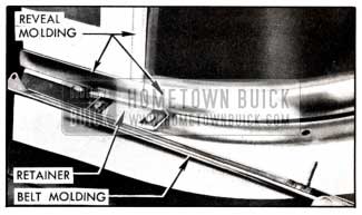
The Series 50-70 front end belt molding consists of two sections, with right hand section overlapping the left hand section at the center. Three bolt type retainers attach each section of molding and one retainer attaches both sections where they overlap at the center. Rubber sealing washers are placed on each retainer bolt between the molding and cowl panel. See figure 13-18. A single screw attaches outer end of each molding to the body pillar.
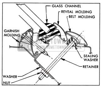
1951 Buick Series 50-70 Belt, Reveal, and Garnish Moldings at Bottom of Windshield
- Remove both wiper blades and arms from windshield wiper transmission shaft.
- On Series 50-70 remove driving burrs, nuts, and escutcheons from windshield wiper transmissions (par. 13-10, e). Remove screws attaching ends of belt molding to body pillars.
- Remove glove box and defroster parts to provide access to belt molding retainer bolt nuts under cowl.
- On Series 40 only, remove both windshield wiper transmission retainers. On all series, remove nuts and washers from belt molding retainer bolts.
- Remove belt molding sections and retainers from outside body. On Series 40, raise wiper transmissions far enough to release the moldings.
- Before installing belt molding on Series 50-70, place sealing washers on retainer bolts, then apply 3-M Weatherstrip Adhesive to bolts around the sealing washers. On all series, apply adhesive to bolt holes in cowl.
- Install belt molding and other parts by reversing removal procedure. On Series 40 make sure that a sealing washer is located at each retainer bolt under cowl and is well sealed.
Replacement of 1951 Buick Windshield Header Molding
The right hand section of 1951 Buick windshield header molding overlaps the left hand section at the center. The sections are attached by six bolt type retainers having barrel nuts located in the windshield header under the headlining. Rubber sealing washers are placed on retainer bolts between the molding and roof panel. See figure 13-19. A single screw attaches outer end of each molding to the body pillar.
1951 Buick Sectional View of Windshield Header Molding Installation
- Remove screws attaching ends of molding to body pillar.
- Remove rear view mirror. Remove escutcheon, both windshield garnish molding sections and the defroster air deflectors attached to moldings with clips. NOTE: When removing right garnish molding, detach radio antenna lead-in cable by removing clips which attach cable to molding.
- Loosen headlining along windshield header and through openings in header remove the six barrel nuts from header molding retainer bolts.
- Remove header molding with retainers and sealing washers from outside of body.
- Before installing header molding, place sealing washers on retainer bolts, then apply 3-M Weatherstrip Adhesive to bolt holes and to bolts around the sealing washers.
- Install header molding, place barrel nuts on retainer bolts and tighten firmly. Apply adhesive to screw holes at outer ends of molding sections and install attaching screws.
- Tack headlining to windshield header and install garnish molding and rear view mirror. NOTE: When installing right garnish molding, attach antenna lead-in cable to molding with clips as described in paragraph 11-9 (c, step 7).
Replacement of 1951 Buick Windshield Reveal and Center Division Moldings
1951 Buick Windshield reveal moldings are attached by a flange inserted into a groove of the windshield glass rubber channel. They cannot be replaced except when the windshield glass and channel assembly is removed from body opening as described in paragraph 13-12.
The 1951 Buick windshield outer division molding used with two piece 1951 Buick windshields is retained by barrel nuts in the inner division molding. The lower end of outer molding is retained by the front end belt molding.
To remove outer division molding, remove belt molding retainer nut and washer at center of body under instrument panel, remove barrel nuts from inner division molding, then remove outer molding. Before installing molding, seal around molding retaining screw holes on glass rubber channel with 3-M Autobody Sealer.
Replacement of Rear Quarter Belt Moldings – Styles “19” and “69”
The right hand section of rear quarter molding overlaps the left hand section at the center. The sections are attached by bolt type retainers and the ends are attached to body lock pillars by screws. On Style “69” each section is also retained at lower corner of back window by a retainer attached to body panel.
- On Style “19” only:
- Remove rear seat cushion and back (par. 13-19).
- Remove rear quarter garnish and belt finishing moldings as a unit.
- Remove rear quarter trim pad far enough to uncover inspection hole in rear quarter inner panel. Trim pad is tacked along the forward edge and anchored at upper rear corner with a drive nail.
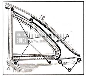
- Through inner panel inspection hole “A” remove the rear quarter belt molding retaining nut, cup washer and rubber washer. See figure 13-22.
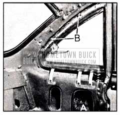
1951 Buick Rear Quarter Ventilator Inside Area
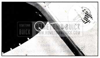
- In rear compartment, remove all nuts, cup washers and rubber washers retaining the rear quarter belt molding. See figure 13-20.
1951 Buick Rear Quarter Belt Molding Installation
- On outside of body remove the screw attaching ends of belt molding to body lock pillar, then remove molding sections. On Style “69” the belt molding slips over a retainer located at lower corners of window opening; remove retainer also. See figure 13-21.
1951 Buick Rear Quarter Belt Molding Retainer-Style 69
- Before installing belt molding, seal around each retainer bolt hole with 3-M Autobody Sealer and apply a ribbon of this sealer around each bolt. On Style “69” body, seal around screw holes and install the belt molding retainers. Apply 3-M Weatherstrip Adhesive to the retainer cup rubber washers.
- Complete the installation by reversing procedure for removal.
Replacement of Rear Quarter Ventilator Header Molding – Style “19”
- Remove rear quarter belt molding (subpar. d, above).
- Above rear quarter ventilator at “B,” inside the body, remove the two barrel nuts and washers securing the header molding. See figure 13-22.
- Remove the single screw holding end flange of header- molding to body lock pillar, then remove the two screws holding lower end of molding to rear quarter panel.
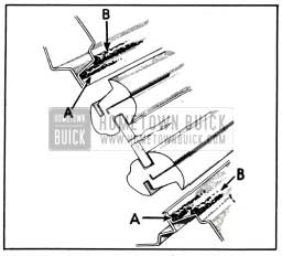
- Before installing header molding, apply continuous heads of 3-M Autobody Sealer to metal flanges of rear quarter pillar from lower corners upward as indicated at “A” in figure 13-23. Circle each screw hole with sealer as indicated at “B.”
1951 Buick Sealing of Ventilator Header Molding
- Install header molding by reversing procedure for removal.
Replacement of Back Window Reveal Moldings
Reveal moldings on the one-piece back windows, and upper reveal moldings on the three-piece back windows, are retained by bolt type retainers. Corner angle moldings, where used, are attached by bolt type retainers. Retainer bolt nuts can be reached by removing the back window garnish molding.
Lower reveal moldings on three-piece back windows are retained by clips inserted into grooves in the window glass rubber channel. Clipped molding can only be replaced after the glass and channel assembly is removed from window opening as described in paragraph 13-13.
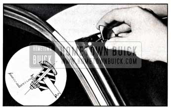
Use new retainers when installing reveal molding, since old ones have been cut off after installation. Place retainers in molding with short side of plate toward the inner or glass side of molding. See figure 13-24.
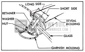
1951 Buick Reveal Molding Retainer Installation
Seal retainer bolts with 3-M Weatherstrip Adhesive before installation of molding. After installation, draw nuts up firmly then cut off surplus ends of bolts to provide clearance when garnish molding is installed.
Replacement of Door Lower Reveal Molding
- Remove door trim pad (par. 13-16) and inspection hole cover from door inner panel.
- Remove the four screws attaching cam to lower sash channel (fig. 13-33) and lower the window glass below sill of window opening.
- On front door only, remove door ventilator (par. 13-15) and remove rivet attaching rear end of reveal molding to flange of door at lock pillar.
- Remove screws attaching molding to retainers on door, then lift molding up to remove it. See figure 13-25.
1951 Buick Door Lower Reveal and Belt Molding Attachments
- Before installation of reveal molding apply 3-M Autobody Sealer along inside of outer curled edge, (fig. 13-25), then install molding by reversing procedure for removal.
Replacement of Door Belt Molding
- Remove door lower reveal molding (subpar. g, above).
- Remove screws and reveal molding retainers along lower edge of window opening, then remove belt molding. See figure 13-25.
- Before installation of belt molding, apply 3-M Autobody Sealer along inside of outer curled edge (fig. 13-25), and to all retainer screw holes, then install molding by reversing procedure for removal.
Replacement of Door Upper Reveal Molding
- Remove garnish molding and upper section of glass run channel (par. 13-14, b and c).
- On front door only, remove door lower reveal molding (subpar. g, above) and ventilator rain deflector.
On rear door only, remove rear reveal molding if this molding is present. On door having stationary window, remove screw retaining escutcheon to header at upper forward edge of stationary glass.
- On doors having a header molding installed over the reveal molding, loosen door weatherstrip and remove screws retaining header molding to door flange.
- Remove reveal molding retaining clips from pinchweld of door header and remove molding.
- Clips on front doors are spring type that snap over pinchweld flange. Clips on rear doors are retained by screws.
- Before installation of reveal molding apply 3-M Autobody Sealer along inside of outer curled edge, then install molding by reversing the removal procedure.
Replacement of Rear Quarter Reveal Moldings
- Remove upper garnish molding and upper section of glass run channel (par. 13-14, b and c).
- Remove reveal molding escutcheon and upper reveal molding retaining screws from inside body and remove these parts.
- Remove rear quarter window glass (par. 13-14), remove lower reveal molding retaining screws, then lift up lower reveal molding to free it from retainers mounted along lower side of window opening.
- Before installation of moldings apply 3-M Autobody Sealer along inside curled edge, then install by reversing the removal procedure. When installing glass run channel make sure that lower rear end is first threaded into its retaining spring clip.
13-12 WINDSHIELD GLASS REPLACEMENT
The windshield glass is mounted in a molded rubber channel which fits over a pinchweld flange formed by the body panels around the windshield opening. The reveal molding which covers the rubber channel on the outside is retained by a flange which hooks into a groove in the channel.
The procedure for removal, installation and sealing of a windshield glass and channel is essentially the same on all models, with the exception of variations caused by differences in the reveal moldings, and header moldings, when used. To replace one glass of a two-piece windshield, the complete two-piece glass and channel assembly must be loosened from the body opening since the engagement of the reveal molding flange in the rubber channel prevents replacement of one glass while the other side .is anchored in place.
Replacement of 1951 Buick Windshield Glass Only
When a windshield glass is broken by accident or other condition which does not indicate a fault in windshield mounting, it is not necessary to remove the complete windshield glass, channel, and reveal molding assembly in order to replace the glass unless the channel and moldings are also damaged.
The windshield glass may be removed from the rubber channel by loosening channel from body opening along the top and sides only, leaving the bottom side attached. When glass and channel are pushed outward from opening at the top and reveal moldings are removed from rubber channel, the old glass can be removed and new glass installed in the channel without difficulty.
When it is only necessary to replace a windshield glass, use the following procedures far enough to effect removal, installation, and sealing of the glass as outlined above. If a faulty glass mounting is indicated, however, use the complete replacement procedures to insure correction and proper mounting of the new glass.
Removal of 1951 Buick Windshield Glass, Channel and Moldings
- Place suitable coverings over hood, front fenders, and instrument panel to protect finish.
Also apply masking tape adjacent to windshield assembly to cover any exposed finish on upper front body pillars and roof panel of car in the working area.
- Remove rear view mirror. On a model where the rear view mirror bracket forms the inside escutcheon for the radio antenna control, remove the radio antenna. (par. 11-9, d).
- Remove windshield garnish molding. On a two-piece windshield remove inner division molding. NOTE: When removing right garnish molding, detach radio antenna lead-in cable by removing clips which attach cable to molding.
- Remove reveal molding corner escutcheons, if present. Each escutcheon is attached by a bolt running through the glass channel with nut inside the body. See figure 13-26.
1951 Buick Reveal Molding Corner Escutcheon
- Remove reveal molding escutcheon at radio antenna, and remove windshield header molding (par. 13-11, b) if these parts are present. Also remove any screws attaching the side reveal moldings to body pillars.
- Remove the front end belt molding (par. 13-11, a).
- First, use a putty knife to loosen the seal between rubber channel and pinchweld flange. Then, with a helper stationed on the outside of the body, carefully force the assembly outward with palm of hand against inside surface of glass, starting at either upper corner and working across top of assembly as the separation of channel lip from pinchweld flange progresses. Move entire upper portion of assembly forward, then work out the bottom section of the rubber channel so that it clears the wiper transmission shafts and lower pinchweld flange.
On Series 50-70, if interference between lower reveal molding and wiper transmissions prevents removal of assembly, release the lower molding from rubber channel before attempting to remove assembly.
- Lift the glass, channel, and reveal molding assembly clear of body and place it on a covered bench.
- Curl back the lip of glass channel and remove reveal moldings, then remove the channel from windshield glass.
Installation of 1951 Buick Windshield Glass, Channel and Moldings
- If the glass rubber channel was sealed with the original factory compound which has a neutral color, clean sealing compound from the pinchweld flange with a putty knife or a dry rag. It is not necessary to remove this sealer from the rubber channel. Do not use solvents (oleum spirits, gasoline, etc.) to clean off this type of sealing compound.
If the glass rubber channel has been previously reset with one of the black sealing compounds used in service, it may be necessary to use oleum spirits or a similar solvent to clean off the old compound.
- Carefully check the pinchweld flange for high spots which would impart a strain on the glass. Use the glass as a template to check flange for proper contour to fit the glass. Correct any irregularities by filing or hammering the flange.
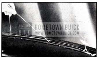
- With new glass on a bench, install the rubber channel around edges of glass. Do not pry edge of glass with a metal tool. Insert a strong cord into the pinchweld groove of rubber channel. Referring to figure 13-27, start at upper corner indicated at “A,” then follow across the top, down the side, and along the bottom to the wiper shaft location.
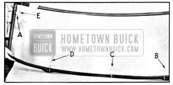
1951 Buick Assembly of Glass and Rubber Channel
At this point, make a loop in the cord and into this loop insert a short section of cord indicated at “B.” At bottom center of long cord make another loop indicated at “C.” At opposite wiper section of channel indicated at “D” loop the cord and insert another short section. Follow up the remaining side and cross both ends of the cord at the upper corner indicated at “E.”
Tape ends of cord to inside surface of glass as illustrated.
- Insert the flange of reveal moldings into the groove in rubber channel. See sectional view in figure 13-18.
- Apply continuous bead of 3-M Autobody Sealer completely around the windshield opening at (1) outer corner of pinchweld flange and (2) outer corner of windshield opening rabbet as indicated in figure 13-28.
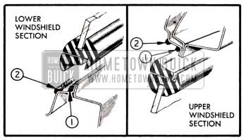
1951 Buick Location of Windshield Sealing Compounds
On two-piece 1951 Buick windshield also apply a bead of sealer across the top and bottom of windshield center division bar.
- With a helper, place the glass and channel assembly in position in body opening. Where the wiper shafts extend through the rubber channel use a light application of liquid soap around the shafts to aid in pushing the rubber over the shafts.
- With helper holding glass firmly in the opening, carefully pull the looped cord along the bottom, only as far as the wiper shafts, so as to fold the lip of the rubber channel over the pinchweld flange. See figure 13-29.
1951 Buick Pulling Lip of Channel Over Pinchweld Flange
- Grasp ends of cord at upper corners of windshield and pull across the top and down the sides to pull lip of channel over pinchweld flange, stopping at windshield wiper shafts. While helpers exert a lateral pull to keep the cord taut, pull up on loose ends of the short cords until lip of channel pulls over pinchweld flange in area between wiper transmissions.
- Using trigger gun B 182-A, apply 3-M Weatherstrip Adhesive between outer lip of rubber channel and the glass all around the channel; also apply adhesive around the shaft and washer outlet of wiper transmission.
- Complete the installation by reversing the procedures for removal of parts. Use 3-M Autobody Sealer to seal around molding escutcheons and bolts. Use 3-M Weatherstrip Adhesive to seal screw holes and other points where a lighter bodied sealer is required.
NOTE: When installing right garnish molding, attach antenna lead-in cable to molding with clips as described in paragraph 11-9 (c, step 7). If radio antenna was removed, reinstall antenna as described in paragraph 11-9 (d).
13-13 BACK WINDOW GLASS REPLACEMENT
Back window glasses are mounted in a molded rubber channel which fits over a pinchweld’ flange formed by the body panels around the window opening.
The reveal molding which covers the rubber channel on the outside is retained by bolts and in some cases by clips which engage a groove in the rubber channel.
The procedure for removal, installation and sealing of a back window glass is essentially the same on all models, with the exception of variations caused by differences in the reveal moldings. To replace one glass of a three-piece back window, the complete three-piece glass and channel assembly must be removed from the window opening as described in the following procedure.
Removal of Back Window Glass Assembly
- Apply masking tape around back window opening and place protective covers where necessary to protect finish and trim.
- Remove rear seat cushion. On styles where the seat back interferes with removal of window garnish molding remove the seat back (par. 13-19).
If body has a center arm rest, remove arm rest extension strap retainer by removing two screws concealed under upper end of strap, then remove seat back trim valance by removing all screws attaching it to the shelf panel.
- Remove window garnish molding; also remove inner division moldings on 3-piece window.
- On styles where the rear quarter belt molding overlaps window reveal molding remove the belt molding (par. 13-11, d).
- On Style “19” remove ventilator header moldings (par. 13-11, e).
- On inside of body remove nuts from all reveal molding retainer bolts, located under the lip of the rubber glass channel.
- On outside of body remove outer division moldings (3-piece window) and all bolted sections of reveal molding. Mark location of retainer bolt holes on masking tape around window opening to aid in reinstallation. Do not pry on reveal molding sections which are retained by clips instead of bolts.
- With a flat blade tool, loosen the rubber channel from sealer around opening, then with a helper stationed on outside of body, apply moderate hand pressure against the glass from inside the body and carefully force the glass and its channel to release from the pinchweld flange. Start at One side and work across top of assembly to opposite side.
- From outside of body with the aid of a helper, grasp each end of loose back window assembly, lift up and remove assembly from opening.
- Place glass and channel assembly on a covered bench. Remove clipped type reveal molding, if present, then carefully disengage rubber channel from glass sections. Do not pry edges of glass with a metal tool.
Installation of Back Window Glass Assembly
- If the glass rubber channel was sealed with the original factory compound which has a neutral color, clean sealing compound from the pinchweld flange with a putty knife or a dry cloth. It is not necessary to remove this sealer from the rubber channel. Do not use solvents (oleum spirits, gasoline, etc.) to clean off this type of sealing compound.
If the glass rubber channel has been previously reset with one of the black sealing compounds used in service, it may be necessary to use oleum spirits or a similar solvent to clean off the old compound.
- Carefully check the pinchweld flange for high spots which would impart a strain on the glasses. Use glasses for templates to check flange for proper contour. Correct any irregularities by filing or hammering.
- On a covered bench, install window glass in the rubber channel, making sure that the etched trade mark on glass is at bottom of the assembly. Using a mild soap solution in groove of rubber channel will aid installation. Do not pry on edges of glass with a metal tool.
On three-piece back window, install the center section in rubber channel first, then install the side sections.
- Insert strong cords into the pinchweld and division bar grooves of rubber channel around each individual section of glass. Tie each cord snugly and tape ends to inside surface of glass. See figure 13-30.
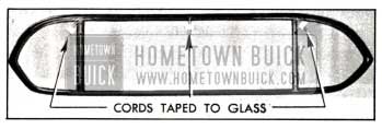
1951 Buick Channel and Cords Installed on Glasses
- Install reveal molding sections which are retained by clips by inserting the clips into the groove in rubber channel.
- Apply continuous beads of 3-M Autobody Sealer completely around the window opening at (A) outer corner of pinchweld flange and (B) outer corner of window opening rabbet. See figure 13-31.
1951 Buick Location of Back Window Sealing Compounds
- With a helper, place glass assembly in window opening and align bolt holes in channel with marks previously made on masking tape. While helper holds glass assembly firmly in place, pull out the cords on inside to fold the lip of rubber channel over the pinchweld and division bar flanges.
- Using trigger gun B 182-A, apply 3-M Weatherstrip Adhesive under outer lip of rubber channel all around each glass section.
- Insert retainers into bolted type reveal molding sections. The short side of retainer plate must be placed toward inner or glass side of molding. See figure 13-24.
- Apply 3-M Autobody Sealer around all bolt holes in rubber channel, then install all reveal molding sections and the outer division moldings (3 piece window).
- On inside of body, install washers and nuts on reveal molding retainer bolts and draw up to a snug fit. Cut off excess ends of bolts to permit lip of rubber channel to cover the nuts.
- Complete the installation by reinstalling the remaining moldings and other parts removed, paying attention to the following items:
- Seal and install ventilator header moldings as described in paragraph 13-11 (e).
- Seal and install rear quarter belt molding as described in paragraph 13-11 (d).
- Clean off all excess sealer and remove protective covering.
13-14 DOOR AND REAR QUARTER WINDOWS-CLOSED BODIES
NOTE: The Riviera, Style “37”, door and rear quarter windows are similar to the windows on convertible coupes except that on Models 45 R and 56 R they are manually operated by regulators instead of the Hydro-Lectric Power System. For service procedures on Style “37” windows refer to Section 13-E.
Description of Windows
Each door and rear quarter window has a safety plate glass which slides vertically in felt glass run channels. Fabric weatherstrips attached to the lower reveal molding and to the inside garnish or belt finishing molding seal the glass along lower side of window opening and assist in preventing vibration of the glass.
The lower edge of door and rear quarter window glass is sealed into a metal sash channel. A channel-shaped cam or track attached to the sash channel is engaged by knobs on the main and idler arms of the window regulator assembly mounted on door or rear quarter inner panel. A knob on the opposite end of regulator idler arm slides in a channel-shaped regulator cam or track mounted on inner panel. The cams cause the arms of window regulator to apply evenly distributed pressure on lower sash channel to raise or lower the glass without tilting and binding in glass run channels.
The procedures given in this paragraph are for door windows; however, the same general methods are applicable to replacement of similar parts of the rear quarter windows. The principle difference is that rear quarter windows do not have window division channels.
Replacement of Garnish and Inside Belt Finishing Moldings
- Remove inside safety locking rod knob by unscrewing it from the rod.
- On Series 50-70 front door, remove ventilator regulator handle by pushing inward on the escutcheon and removing handle retaining spring, using Door Handle Pliers KMO 601. See figure 13-35.
- Remove garnish molding attaching screws, then grasp upper horizontal portion of molding and pull away from door with a downward motion to release it. On Series 50-70, remove the rubber grommets which slip over lower ends of molding.
- To remove Series 50-70 belt finishing molding, remove retaining screws at both ends then lift molding up to free it from retaining clips.
- Install moldings by reversing removal procedure.
Replacement of Glass Run Channel
Series 40 window glass run channels are made in one section. Series 50-70 glass run channels are made in upper and lower sections.
- Remove garnish molding (subpar. b, above).
- To remove upper section of glass run channel on Series 50-70, pry clips of upper section of door glass run channel from pinchweld flange of window opening and remove the upper section. When removing rear quarter glass run channel, remove the retaining screw at rear of window opening, pry channel toward inside of body to release retaining clips, then pull up to release lower end of channel from its retaining spring clip.
- To remove lower section of glass run channel on Series 50-70, or entire section of channel on Series 40, remove door trim pad (par. 13-16) and the inspection hole cover adjacent to lower end of channel.
- Remove screw that retains lower end of channel to door pillar. On Series 40 release channel from clips along door header and pillar.
- Pull channel up through window glass opening, using care to avoid denting the metal bead on channel.
- To install channel sections reverse the removal procedure. When installing rear quarter channel make sure that lower rear end is first securely engaged in its retaining spring clip.
Replacement of Window Division Channel
NOTE: On Series 40 front doors the division channel is integral with the door ventilator assembly and can only be replaced with the assembly as described in paragraph 13-15 (d). On rear doors having small stationary window the division channel is a separate piece that can be replaced as described below.
- Remove door trim pad (par. 13-16) and release the clips in the glass run channel adjacent to the window division channel and drop it down out of position.
- Remove the retaining screw holding upper end of division channel to door header and remove the two self-tapping screws attaching division channel to the top edge of door inner panel. See figure 13-32.
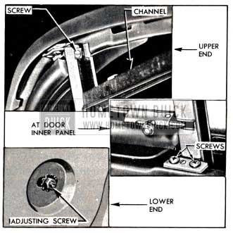
1951 Buick Window Division Channel Attachments
- Remove nut and adjusting screw at the bottom of division channel, noting before removal the length of the screw projecting out from inner panel. This will aid proper adjustment when installing channel.
- With the door ventilator open, swing division channel out of position, pull up and remove through the window opening of door.
- When division channel is installed by reversing procedure for removal, adjust the screw at lower end of channel to same length as it was before removal. Operate the door window and the ventilator to see whether the division channel is properly positioned for smooth operation of window glass and full closing of ventilator.
If channel is not properly positioned, adjust the lower end in or out, forward or rearward at the screw as required to obtain free movement of window glass.
Replacement of Door Window Glass
- Remove door trim pad (13-16) and remove inspection hole covers to provide access to lower sash channel screws. Remove garnish molding retaining clips from door inner panel, if present.
- On all Series 40 doors except Style “69” rear doors, remove ventilator and division channel assembly (par. 13-15, d). On Style “69” rear door remove ventilator division channel.
On Series 50-70, remove glass run channel and window division channel (subpar. c and d, above).
- With glass in lowered position, remove screws attaching the cam to lower sash channel. See figure 13-33.
1951 Buick Window Regulator and Cam Attaching Screws
- Carefully raise the glass to an almost closed position and tilt inward using care to work out.one lower corner at a time to avoid damage.
- Install glass by reversing removal procedure. Before installing trim pad (par. 13-16) raise and lower the window glass several times to check for smooth operation.
If glass binds or has excessive edgewise play it may be necessary to adjust the window division channel at lower end.
If glass tilts edgewise, adjust the regulator cam (fig. 13-33) at rear end where the attaching screw hole is slotted vertically. Raise rear end of cam to throw travel of glass forward or lower rear end to throw travel of glass rearward.
Replacement of Door Window Regulator
- Remove trim pad (par. 13-16) and inspection hole cover to provide access to lower sash channel screws.
- On Series 40 front door only, remove door window glass (subpar. c above). On all other doors remove screws attaching the cam to lower sash channel (fig. 13-33) then raise glass to closed position and support it there.
- Slide the sash channel cam off the ends of regulator arms.
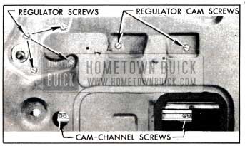
- Remove four screws attaching window regulator, and two screws attaching regulator cam to door inner panel. Remove regulator and cam through inspection hole, using care to avoid scratching window glass.
- To install regulator and cam, set regulator in place, install ca-m over knob on idler arm and install regulator and cam attaching screws. The hole in inner panel for cam screw nearest lock pillar is slotted vertically. Set the screw at top of slot when tightening it.
- After installation of lower sash channel cam, raise and lower window glass several times to check for smooth operation of glass in run channels. If glass binds or has excessive edgewise play it will be necessary to adjust the window division channel at lower end. If glass tilts edgewise, adjust the regulator cam at slotted screw hole as required.
- Seal and install inspection hole cover, install covering over small hole in panel, and install trim pad, (par. 13-16).
Replacement of Rear Door Stationary Window
On Series 40 Style “69” bodies, the rear doors have small stationary windows in place of ventilators.
- Remove door trim pad (par. 13-16) and window division channel.
- Slide entire glass and rubber channe1 assembly toward center pillar to clear the metal retaining tabs, then exert pressure on assembly toward inside of door and remove the assembly.
- Remove glass from rubber channel if required.
- Reverse the removal procedure to install the parts. During installation of glass and channel pull outer lip of rubber channel up over door outer panel.
13-15 DOOR AND REAR QUARTER VENTILATORS-CLOSED BODIES
NOTE: The Riviera, Style “37,” door ventilators are similar to the door ventilators on convertible coupes. For service procedures on Style “37” door ventilators refer to Section 13-E.
Description of Ventilators
Each ventilator has a safety plate glass sealed into a metal channel which is pivoted vertically. When a ventilator is closed it is sealed against passage of wind, water and dust by contact with a molded rubber weatherstrip attached to the door and the window division channel.
Door ventilators are operated by a regulator mounted on the door inner panel. A bolt type lock riveted to the glass channel provides a lock for the ventilator. See figure 13-34.
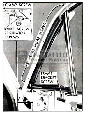
1951 Buick Ventilator and Regulator Mounting Series 50-70 Shown
Rear quarter ventilators have a friction mechanism to hold ventilator in desired position and an inside locking handle. The friction mechanism is a part of the ventilator frame and consists of a heavy coil spring mounted on the frame spindle to exert frictional force against the mounting support. The spring pressure is set at the factory to give the best possible balance between ease of operation and resistance to closing under wind pressure, and usually will not require further adjustment. If the ventilator does not remain in set position when car is in motion, the spring pressure and friction may be increased by removing the ventilator assembly and tightening the nut at lower end of ventilator frame spindle.
Door Ventilator Regulator Adjustment
Excessive play at ventilator lower pivot may be corrected by tightening the clamp screw which attaches the glass channel T-shaft to ventilator regulator. See figure 13-34.
Excessive looseness or tightness in operation of the ventilator regulator may be corrected by adjusting the screw which controls the brake or friction clamp on the regulator. See figure 13-34.
To tighten the clamp screw or adjust the brake screw it is necessary to loosen door trim pad sufficiently to provide access to these screws (par. 13-16).
If ventilator glass does not fit evenly, up and down, against molding on window division channel, or ventilator lock does not slide to locked position with moderate pressure, it is usually necessary to adjust the division channel. This adjustment, however, should be limited so as not to cause a looseness or bind in the fit of the door window. See paragraph 13-14. (d).
In some cases of misalignment of ventilator in door opening it may be necessary to loosen the ventilator frame and the weatherstrip and shift these parts slightly. When proper alignment is secured the frame must be tightened securely and the weatherstrip must be cemented to window reveal with 3-M Weatherstrip Adhesive.
Replacement of Ventilator Regulator
- Remove garnish molding and door trim pad (par. 13-16) and remove inspection hole cover located below ventilator.
- Remove clamp screw which attaches glass channel T-shaft to regulator, also the regulator attaching screws. See figure 13-34.
- Remove regulator through inspection hole in door inner panel.
- Install regulator by reversing the removal procedure. Adjust the brake screw (fig. 13-34) to provide proper operating tension on regulator before attaching trim pad.
Replacement of Door Ventilator Assembly
NOTE: On Series 40, the division channel is integral with the ventilator assembly. On Series 50-70, the division channel is not integral with the ventilator assembly.
- Remove trim pad (par. 13-16) and the ventilator regulator (subpar. b, above).
- On Series 40, remove the division channel lower adjusting stud nut and washer. Lower door glass and release the glass run channel along the door header. On Series 50-70, remove the division channel (par. 13-16, d).
- Remove screws attaching ventilator frame bracket to door inner panel. See figure 13-34.
- Remove screws attaching ventilator frame to door hinge pillar. On Series 40, these screws are concealed behind inside lip of ventilator weatherstrip; on Series 50-70, screws are on outer face of door hinge pillar.
- Carefully loosen weatherstrip where cemented to window reveal, then remove the ventilator assembly.
- When ventilator assembly is installed by reversing removal procedure, apply 3-M Autobody Sealer between contacting surfaces of ventilator frame attaching brackets and door inner panel. Also apply a bead of 3-M Weatherstrip Adhesive on lip of weatherstrip at ventilator upper pivot to bridge the cutout in retainer at this point. Seal between lip of weatherstrip and the reveal moldings.
- Before installation of trim pad (par. 13-16) operate the door window and the ventilator to see whether the division channel is properly adjusted. The lower end of channel may be adjusted forward, rearward, in, or out at the adjusting stud at lower end.
Leave A Comment
You must be logged in to post a comment.