SECTION 2-G SERVICE ON 1951 BUICK ENGINE MOUNTINGS, FLYWHEEL AND HOUSING
2-31 1951 BUICK ENGINE MOUNTING ADJUSTMENT
The following procedure must be used to center the engine in the frame and adjust the 1951 Buick engine mountings and transmission mountings.
- Disconnect torque tube from torque ball.
- Tighten 1951 Buick engine mounting brackets to the crankcase and frame front X bar. Loosen the engine front mounting pad top stud nuts.
- Tighten transmission support to frame X member attaching bolts.
- Tighten transmission mounting pad to transmission support and to transmission rear bearing retainer.
- Tighten thrust pad to thrust plate stud nuts (rear) and loosen thrust pad to transmission support stud nuts (front). Remove shims between thrust pad and transmission support.
- Measure the distance between the front edge of crankshaft balancer, at horizontal centerline, and the center of the nearest shock absorber bolt head on each side. If distances on both sides are not equal, shift front of engine sidewise as required to center engine in frame, then tighten engine mounting pad stud nuts securely. The mounting pad stud holes in 1951 Buick engine mounting brackets are oversize to permit sidewise adjustment of engine.
- With engine and transmission resting freely and normally on 1951 Buick mounting pads, install sufficient shims between the thrust pad and transmission support to snugly fill the existing space. Insert shims from above, with tabs on right side in Synchromesh cars or left side in Dynaflow Drive cars. See figure 2-40.
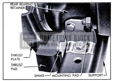
1951 Buick Transmission Mounting Pad, Thrust Pad and Shims
- Tighten thrust pad front stud nuts and tighten front engine mounting pad stud nuts.
- Connect torque tube to torque ball.
2-32 1951 BUICK FLYWHEEL OR RING REPLACEMENT – SYNCHROMESH ENGINE
Removal of Flywheel (synchromesh only)
Flywheel and ring assemblies are balanced separately from the crankshaft during manufacture; however, all completely assembled engines are given a running balance test in a special machine during production. In this test the flywheel is drilled, if necessary, to finally balance the entire engine to very close limits. For this reason, the flywheel and the crankshaft flange should be marked before flywheel is removed so that flywheel may be reinstalled in its original position on the crankshaft. It is also advisable to run the engine after the clutch is removed to note the degree of vibration with the original flywheel.
Flywheels are attached to the crankshaft with bolts, lockwashers and nuts. It is necessary to remove the crankshaft rear bearing cap and remove bolts from crankshaft in order to remove the flywheel. CAUTION: When turning crankshaft with rear bearing cap removed, hold the bearing inner oil seal to prevent it from moving out of the groove in crankcase.
Replacement of Flywheel Ring (synchromesh only)
To remove a flywheel ring from the flywheel, drill a 5/16″ hole in the ring between two teeth and split the ring at this point with a cold chisel.
The flywheel ring is a shrink fit on the flywheel and must be heated to approximately 600° F. in order to expand it sufficiently to go over the flywheel. Heating the ring in excess of 800° F. will destroy the effect of the heat treatment given during manufacture.
Excessive heating may be avoided by first polishing several spots on the ring with emery cloth, then heating the ring only until these spots begin to turn blue. Heat the ring to approximately 600° F. on a hot plate if available; otherwise, place ring on a sheet of metal or asbestos and heat it with a torch that is kept moving to secure even heating. When ring is at proper temperature, quickly place it over flywheel and allow the ring to cool slowly until it is tight in place.
Installation of Flywheel (synchromesh only)
If old flywheel is being reinstalled be sure to place it in original position on crankshaft flange in accordance with marks made before removal.
If a new flywheel or a new crankshaft is being installed, the flywheel bolt holes must be reamed to provide a very close fit for the bolts. Two bolt holes are reamed to size in replacement flywheels and crankshafts. Use these reamed holes to bolt the parts together, then ream the other holes and install bolts.
After installation of a new flywheel or a new flywheel ring, be sure to run the engine and check for vibration before installing the clutch. If engine has vibration that did not exist before installation of new parts, make correction as described under Correction of Engine Vibration (par. 2-34).
2-33 1951 BUICK FLYWHEEL HOUSING ALIGNMENT – SYNCHROMESH ENGINE
The flywheel housing is attached to the cylinder crankcase with six 7/16″ bolts. Two 1/2″ straight dowel pins are installed in reamed holes in both parts to maintain alignment.
Misalignment between the pilot in rear face of housing and the pilot bearing in rear end of crankshaft may cause the transmission to be noisy or to slip out of high gear. To insure correct alignment in production, the pilot hole which receives the transmission main drive gear bearing is bored in the housing after it is assembled to the cylinder crankcase. The flywheel housing furnished for service is completely machined, but it must be checked for alignment after installation.
If an existing housing is suspected of being out of alignment it may be checked after removal of the transmission and clutch assemblies. If a new housing or cylinder crankcase is being installed, alignment should be checked before the flywheel, clutch and transmission are installed. When checking alignment the engine must be in an upright position, dowel pins must be installed, and all housing bolts must be tight.
Checking Alignment of Flywheel Housing (synchromesh only)
- Remove transmission (par. 4-13) and clutch (par. 4-5), leaving flywheel in place.
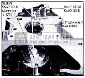
- Attach Indicator Support J 4710-1 to flywheel with two flywheel bolts. Mount Dial Indicator KMO 30-B and Hole Attachment KMO 30-F on pilot with Sleeve KMO 30-K. Adjust ball end of hole attachment to bear against side of pilot hole in flywheel housing. See figure 2-41.
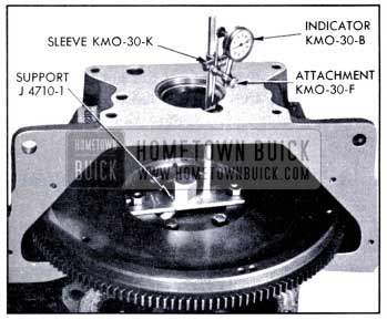
1951 Buick Checking Alignment of Flywheel Housing
- Turn flywheel very slowly and note total run-out of pilot hole as shown by dial indicator. If total indicator reading is .005″ or less, flywheel housing alignment is satisfactory. If runout exceeds .005″, correction must be made as described in subparagraph b, below.
Correction of 1951 Buick Flywheel Housing Misalignment (synchromesh only)
- Remove flywheel (par. 2-32), housing, and dowel pins. Reinstall crankshaft rear bearing cap.
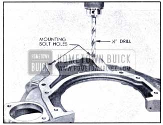
- Drill out the two upper bolt holes in flywheel housing and the four bolt holes in crankcase flange with a 1/2″ drill. See figure 2-42 and 2-43.
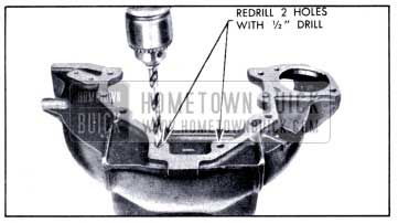
1951 Buick Enlarging Bolt Holes in Housing
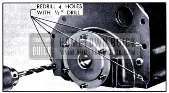
1951 Buick Enlarging Bolt Holes in Crankcase Flange
- Install flywheel housing without dowel pins, and leave bolts just loose enough to permit shifting of housing by tapping with lead hammer. NOTE: Use sealing compound on flywheel housing upper bolt on camshaft side to prevent oil leaking into flywheel housing.
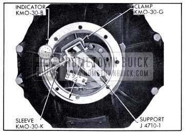
- Install dial indicator as shown in figure 2-44 and check run-out at pilot hole in housing.
1951 Buick Aligning Housing
- Shift housing by tapping with lead hammer as required to bring run-out at pilot hole within .002″ indicator reading. Tighten housing bolts and re-check run-out.
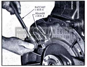
- Using Special Reamer J 2548-3 and Ratchet Wrench J 808-6 (shown in fig. 2-48), ream the dowel holes and install two oversize dowel pins J 808-5.
- Mount dial indicator on crankshaft flange and set to bear against rear face of flywheel housing at a radius of 2 1/2″.
- Turn crankshaft and note run-out of housing rear face, making sure that end thrust of crankshaft is all one way while making this check. If total indicator reading exceeds .003″, shellac paper shims of proper thickness in position required to give an indicator reading of .003″ or less.
- Install flywheel, clutch (par. 4-5), and transmission (par. 4-13).
2-34 CORRECTION OF UNBALANCED SYNCHROMESH ENGINE
An extremely unbalanced engine should always be corrected by replacing parts which are abnormally out of balance or materially different in weight from corresponding parts. The procedure described here is intended only for corrections of minor cases of unbalance which may occur where individually balanced parts are assembled together.
If the vibration developed after removal and installation of clutch assembly, check all clutch cover bolts to make sure they are of same length and that each has one lock washer. Also check marks that were made when clutch was removed and disassembled to make sure that clutch was assembled and installed according to these marks. Make any corrections indicated by this inspection and run engine at the critical speed to check results.
If clutch assembly and installation does not appear to be at fault, mark clutch cover and flywheel and remove clutch assembly (par. 4-5). Run engine at critical speed and check for vibration. If vibration is eliminated, the clutch is at fault and should be balanced as described below. If vibration still exists, however, it will be necessary to balance the flywheel on the crankshaft.
To balance the flywheel, insert one clutch cover bolt successively in each hole in flywheel and check results at each position by running the engine. It may be necessary to vary the test weight by adding washers or by using a shorter bolt. When a proper weight and position has been found to eliminate the vibration, the bolt will be on the light side of flywheel. Remove the bolt and drill shallow holes in diametrically opposite side of flywheel, until enough weight has been removed to make engine run smooth. Use a 3/8″ drill and do not drill any hole more than 1/4″ deep.
Install clutch assembly according to marks (par. 4-5) after making sure that engine runs smooth with clutch removed, and again check for vibration at the critical speed. If vibration exists with clutch installed, install one plain washer under the lock washer of each clutch cover bolt in turn until a location is found where the engine runs smooth. It may be necessary to place plain washers on two adjacent bolts in order to obtain enough weight at the proper location to secure balance.
2-35 REPLACE 1951 BUICK FLYWHEEL HOUSING AND ALIGN BELL HOUSING DYNAFLOW ENGINE
- Remove Dynaflow transmission (par. 4-27) then remove flywheel and flywheel housing.
- Mount the new flywheel housing on engine crankcase and tighten attaching bolts. Do not install dowel pins.
- Attach Indicator Support J 4710-1 to crankshaft flange with two opposite flywheel bolts. See figure 2-45.
1951 Buick Checking Runout of Rear Face of Bell Housing
- Remove bell housing from the transmission and attach it to the flywheel housing.
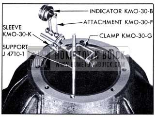
- Mount Clamp KM0-30-G and Dial Indicator KM0-30-B on the indicator support so that dial indicator bears against rear face of bell housing at a radius of 3 3/4″. See figure 2-45.
- Turn crankshaft with an extension and 1″ socket applied to hex of indicator support, making certain that end thrust is held in one direction. Note dial indicator reading as crankshaft is turned; runout of rear face of bell housing should not exceed .005″.
- If runout exceeds .005″, shellac paper shims of proper thickness in place between flywheel housing and engine crankcase to give an indicator reading of .005″ or less.
- Mount Dial Indicator KM0-30-B, Hole Attachment KM0-30-F, and Sleeve KM0-30-K on Clamp KM0-30-G so that hole attachment bears against inner edge of pilot hole in bell housing. See figure 2-46.
1951 Buick Checking Runout of Bell Housing Pilot Hole
- If runout of pilot hole exceeds .004″, loosen flywheel housing bolts just enough to permit shifting of housing by tapping with a lead hammer. Tap in required direction to bring runout of pilot hole to .004″ or less. Tighten mounting bolts and recheck runout.
- If it is not possible to move flywheel housing far enough to obtain specified alignment, remove both housings. Drill the two plain bolt holes in flywheel housing and the four plain bolt holes in crankcase with a 1/2″ drill. See figures 2-43 and 2-47.
1951 Buick Enlarging Bolt Holes in Housing View
- Reinstall both housings and align bell housing at pilot hole as specified in Step 9.
- Remove bell housing and ream the two dowel pin holes through flywheel housing and crankcase flange, using 17/32″ Reamer J 2548-3 and Ratchet J-808-6. See figure 2-48. Install oversize dowel pins J-808-5.
1951 Buick Reaming Dowel Pin Holes
- Install flywheel on crankshaft and check runout of rear face (par. 2-36, b).
- Install bell housing and converter on transmission (par. 4-38, i) then install transmission (par. 4-28).
2-36 REPLACE AND BALANCE FLYWHEEL AND/OR CRANKSHAFT DYNAFLOW ENGINE
Causes of Cracked Dynaflow Flywheel
Cracks around the outer edge of crankshaft bolt holes in flywheel indicate either a faulty flywheel or misalignment between the engine and Dynaflow transmission. Misalignment between engine and transmission may be due to misaligned flywheel housing, bell housing, or primary pump hub.
To determine cause of misalignment, check runout of rear face of bell housing and runout of bell housing pilot hole as described in paragraph 2-35. If runout is not within specified limits, correct the alignment as instructed in that paragraph. If runout of bell housing is within specified limits, install a new flywheel (subpar. b, below) and then check for runout of primary pump hub as described in paragraph 4-37. If pump hub runout is within limits it may be assumed that the flywheel was faulty and flywheel replacement will correct the trouble.
When a cracked flywheel is discovered, a close inspection should be made of the primary pump hub, front oil pump bushing, and front oil pump seal to determine whether these parts have been damaged.
Replace 1951 Buick Dynaflow Flywheel and Check Runout
- Remove Dynaflow transmission (par. 4-27), then remove flywheel.
- Check for burrs around drilled holes in crankshaft flange and face of flywheel to be installed; remove any burrs with a mill file:
- When installing a new flywheel, it is necessary to ream the two dowel holes to avoid deforming the flywheel when it is bolted to the crankshaft. Use a tapered reamer and remove only enough metal from dowel holes to obtain a snug fit of flywheel over the crankshaft pilot and dowel pins. CAUTION: Flywheel must not be forced over the crankshaft pilot and dowel pins.
- Install flywheel and tighten bolts evenly to 50-55 ft. lbs. torque.
- Install one 7/16″ cylinder head bolt in upper hole in flywheel housing. Clamp a strip of .005″ shim stock or spring steel to the bolt so that free end bears against face of flywheel so as to cover the holes and provide a smooth indicating surface. See figure 2-49.
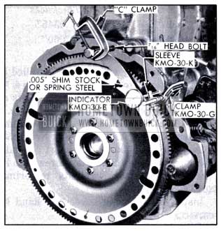
1951 Buick Checking Runout of Flywheel Face
- Attach Clamp KM0-30-G to flange of flywheel housing and use Sleeve KM0-30-K to mount Dial Indicator KM0-30-B to bear against the strip where it contacts flywheel face. See figure 2-49.
- Turn flywheel, making sure that crankshaft end thrust is held in one direction, and note runout of flywheel face. Runout should not exceed .008″.
- If runout exceeds .008″ attempt to correct by tapping high side of flywheel with mallet. If this does not correct runout remove flywheel and check for burrs between flywheel and face of crankshaft flange. Remove burrs and recheck for runout.
- If no burrs exist install a new flywheel and recheck runout. If runout still exceeds .008″, check runout of rear face of crankshaft flange.
- After installation of transmission, test for engine vibration. If vibration has been introduced by installation of new flywheel make correction as described below (subpar. d).
Replacement of 1951 Buick Crankshaft (Dynaflow engine)
Installation of a new crankshaft, with either the old flywheel or a new one, will require reaming of the dowel pin holes and installation of oversize dowel pins.
- After crankshaft is installed, check crankshaft flange and flywheel to make certain they are clean and free of burrs, then install flywheel with dowel pin holes aligned and tighten the six bolts securely.
- Check runout of flywheel face as described above (subpar. b).
- Remove crankshaft rear bearing cap to provide reamer clearance and turn crankshaft so that a dowel pin hole can be reamed. Ream both dowel pin holes through flywheel and crankshaft flange, using Reamer J 2548-3 (shown in fig. 2-48).
- Provide two dowel pins 17/32″ diameter by 9/16″ long, either by sawing pieces from 17/32″ drill rod or by cutting dowels J-808-5 to 9/16″.
Avoid marring outside surface of pins during cutting, and round the ends with a mill file to remove burrs. Tap the two dowel pins through flywheel and flange until ends are flush with rear face of flywheel.
- Install crankshaft rear bearing cap and complete the assembly of engine and transmission.
- Check for engine and transmission roughness or vibration and make any corrections required as described below.
Correction of 1951 Buick Engine and Transmission Vibration
Complete production engine assemblies are dynamically balanced to very close limits; consequently, some cases of vibration may be encountered when replacement crankshafts or flywheels have been installed. The following procedure should be used to correct vibration due to change of balance.
- Remove bell housing cover and bell housing hand hole cover.
- Install one balance weight No. 1337197 (.060″ thick) under heads of the two primary pump to cover bolts which are immediately to left (clockwise) of one converter to flywheel bolt. See figure 2-50. Tighten bolts to 30-35 ft. lbs. torque.
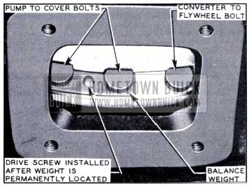
1951 Buick Location of Balance Weight
- Place shift control lever in Parking (P) position, start engine and check vibration at critical speed, then stop engine.
- Remove the balance weight and install under two bolts immediately to left of the adjacent converter to flywheel bolt. Tighten all bolts to prope1• torque. Run engine at critical speed and check vibration.
- Repeat until weight has been installed to left of all six converter to flywheel bolts, in order to determine which location of balance weight produces the least vibration.
- At the location where the least vibration is obtained install weights of proper thickness to eliminate objectionable vibration. Balance weights are available under group 4.115 in the following thicknesses:
Part No. – Thickness
1337196 – .0345″
1337197 – .060″
1337198 – .120″- After balancing weights are installed and all bolts tightened to proper torque, use a 5/32″ drill to spot the center of hole in weights and drill flange of primary pump with a No. 32 (.116) drill, making hole only 3/8″ deep in flange. Select drive screw, Group 8.978, No. 145067 (3/8″ long) or No. 450543 (1/2″ long) depending on thickness of weights and tap screw into hole to permanently attach weights to primary pump.
- Install bell housing cover and hand hole cover.
NOTE: If a satisfactory balance cannot be achieved the new part which caused the unbalanced condition should be replaced and the above procedure repeated.
Leave A Comment
You must be logged in to post a comment.