SECTION 2-D 1951 BUICK CYLINDER HEAD AND VALVE MECHANISM SERVICE
2-14 1951 BUICK VALVE LASH ADJUSTMENT
NOTE: This procedure applies only on Series 40 engines used with Synchromesh transmissions; these engines have plain sleeve valve lifters. All other 1951 Buick engines have hydraulic valve lifters, indicated by a label on rocker arm cover, stating “This Engine Equipped with Hydraulic Lifters.”
For maximum performance in engines equipped for adjustable valve lash, it is imperative that the ROAD OPERATING VALVE LASH BE UNIFORMLY .015″.
Oil, water and engine temperatures must be stabilized or brought to normal operating temperatures before the valves can be properly adjusted for uniform lash. When an engine is warmed up by running without load in the shop, the oil, water and engine temperatures level off at different points than those obtained on the road; therefore, a wider lash adjustment is required in the shop adjustment.
NOTE: An alcohol base anti-freeze in the cooling system will boil before the temperatures become properly stabilized when running engine in the shop; therefore, such anti-freeze must be drained and the cooling system filled with water until valve lash operation is completed, after which the anti-freeze must be reinstalled.
The following procedure must be carefully followed when adjusting valves in the shop, in order to obtain the specified road operating lash.
- Loosen radiator cap to prevent excessive water temperature build-up. Start engine and set speed at a minimum of 700 RPM. NOTE: A lower speed during warm-up will not provide proper circulation through the engine to uniformly stabilize the water temperature.
- Run the engine for 20 minutes. This will bring the oil, water and engine temperatures to a point where change of lash caused by expansion of engine parts will level off and the lash will remain fairly constant for a period of about 10 minutes. During this time the valve lash can be checked and adjusted as required.
- Set engine to idle at 350-400 RPM. Remove rocker arm cover and make sure that valves are being properly supplied with oil.
- Starting at rear of engine, check the lash of all valves with a .017″ and an .018″ feeler gauge. The .017″ gauge should pass between the valve stem and rocker arm without sticking, but the .018″ gauge should not pass through.
CAUTION: Feeler gauges must be smooth and straight.
- Where the lash is either too tight or too loose, loosen the lock nut and adjust the ball stud until a slight drag is felt on a .017″ feeler gauge placed between the valve stem and rocker arm. Tighten lock nut and recheck lash with the .017″ “go” and .018″ “no go” feeler gauges. Quiet valve action depends on uniform valve lash.
- Set engine idle at 450 RPM, then stop the engine.
- Install rocker arm cover, making sure that gasket is in good condition and properly placed to prevent leakage of oil. Tighten radiator cap.
2-15 INITIAL ADJUSTMENT AND CLEANING OF 1951 BUICK HYDRAULIC VALVE LIFTERS
NOTE: Engines equipped with: hydraulic valve lifters are identified by a label on rocker arm cover, stating-” This Engine Equipped with Hydraulic Lifters.”
Hydraulic valve lifters eliminate the need for service adjustment; however, an initial adjustment of hydraulic valve lifters is required after the valves have been refaced, whenever the setting of the adjusting ball stud is disturbed for any reason, or whenever valve lifters are removed and installed.
If the operation of a valve lifter becomes faulty due to excessive varnish deposits or presence of dirt it may be disassembled and cleaned. As long as a valve lifter operates properly, however, it should be left alone. It should not be disassembled and cleaned when removed for other work but should be wrapped in clean paper to avoid entrance of dirt.
Initial Adjustment of 1951 Buick Hydraulic Valve Lifters
The initial adjustment of any hydraulic valve lifter must be made only when the lifter is on the camshaft base circle (off the cam).
- Crank engine over slowly until distributor rotor indicates that affected 1951 Buick cylinder is in firing position, which places both lifters of this cylinder on the camshaft base circle (off the cam), so that either lifter may be adjusted.
- Turn adjusting ball stud as required until all play of push rod between lifter and ball stud is just removed, and there is no lash clearance in the valve train.
- Turn adjusting ball stud down exactly 2 turns. Check to make sure that oil groove on ball stud is at least half way down in rocker arm so that it connects with the drilled oil passage in rocker arm, then tighten the lock nut.
- If oil groove on ball stud is not at least half down in rocker arm, turn ball stud down one additional turn (total 3 turns) and tighten rock nut. If oil groove is still too high, it will be necessary to install another push rod or lifter.
- When it is necessary to adjust all valve lifters in an engine, time may be saved by aligning the “U.D.C. 1-8” mark on flywheel with index mark in timing hole in flywheel housing, first with No. 1 cylinder and later with No. 8 cylinder in firing position as indicated by position of distributor rotor. Adjust lifters according to the following table:
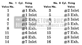
1951 Buick Hydraulic Valve Lifters Adjustment
Cleaning of 1951 Buick Hydraulic Valve Lifter
If it becomes necessary to clean a hydraulic valve lifter because of dirt or varnish, it is advisable to clean all other lifters at the same time because it is likely that they may successively become faulty from the same cause.
A hydraulic lifter may be lifted out of crankcase by inserting the slightly bent end of a stiff wire into the oil hole in push rod seat. A convenient tool for removing lifters may be made from details shown in figure 2-14.
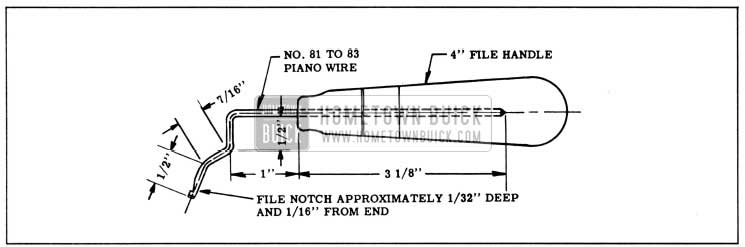
1951 Buick Tool for Removing Hydraulic Valve Lifter
If carbon formation in bore above lifter prevents removal, remove the formation with a clean cloth moistened with a suitable solvent, using extreme care to avoid getting solvent or dirt into the lifter.
Disassemble a hydraulic lifter by removing the plunger retainer with a screwdriver, then removing the other parts from the body as shown in figure 2-15.
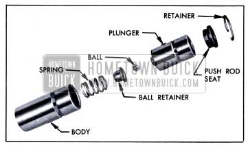
1951 Buick Hydraulic Valve Lifter, Disassembled
When a valve lifter has been in service for a long time, the body bore above the plunger may be caked with hard carbon so that the plunger cannot be removed easily. When this condition exists submerge valve lifter in a suitable carbon softener for a time and then remove the carbon with a stiff bristle brush.
When a hydraulic valve lifter is disassembled use extreme care to avoid nicking or otherwise damaging the body and plunger through contact with other parts. Keep the parts of one lifter separate from all others so that parts will not be interchanged during assembly. Plungers are not interchangeable because they are selectively fitted to the bodies at the factory. –
Wash valve lifter parts in a suitable solvent to remove all traces of varnish or carbon. Carefully inspect surface of plunger and bore of body for scoring or other damage which would prevent free movement between these parts. If such damage exists the lifter assembly must be replaced. The assembly must be replaced if the lower end of body is worn, spalled (small nicks or indentations) or scored with scratched radial lines.
If plunger and body appear satisfactory, blow off with air to remove all particles of dirt. Install plunger in body without other parts and check for free movement. A simple test is to be sure that plunger will drop of its own weight in the body.
Assemble valve lifter parts in the order shown in figure 2-15. Fill lifters with correct seasonal grade of clean engine oil before installation in engine. After installation make initial adjustment as described in subparagraph a above.
2-16 REMOVAL AND INSTALLATION OF 1951 BUICK CYLINDER HEAD
CAUTION: On engines e quipped with hydraulic valve lifters it is extremely important to avoid getting dirt into these unit s. When removing and installing 1951 Buick cylinder head use ever y precaution to keep dirt out of the push rod compartment above the lifters.
Removal of 1951 Buick Cylinder Head and Gasket
- Drain cooling system and disconnect radiator thermostat housing from 1951 Buick cylinder head.
- Remove spark plug cover, disconnect wires from spark plugs and remove spark plugs.
- Disconnect temperature gauge tube and rocker arm oil pipe from 1951 Buick cylinder head.
- Remove air cleaner and disconnect gasoline and vacuum pipes from carburetor and manifold.
- Disconnect rod from carburetor throttle lever. Disconnect return spring and equalizer shaft upper bracket from intake manifold.
- Disconnect exhaust pipe flange from exhaust manifold.
- Remove rocker arm cover then remove rocker arm, shaft, and bracket assembly. Lift out push rods. On some models it may be necessary to remove No. 16 push rod as cylinder head is removed.
- Slightly loosen all 1951 Buick cylinder head bolts, then remove bolts and lift off 1951 Buick cylinder head with manifolds attached.
- For removal and installation of intake and exhaust manifolds, if desired, refer to paragraph 3-12.
Installation of Cylinder Head and Gasket
Installation of 1951 Buick cylinder head and gasket is the reverse of removal procedure, with attention being given to the following instructions.
Before 1951 Buick cylinder head is installed, make certain that all dirt or carbon is blown out of the blind tapped bolt holes in 1951 Buick cylinder crankcase so that bolts may be fully tightened without bottoming in holes. Examine gasket surfaces of cylinder block and head for nicks or burrs and for ridges around bolt holes. Dress off all high metal spots with a good mill file.
Series 40 synchromesh engines use a Steelbestos cylinder head gasket .075 thick. Series 50 synchromesh and the Series 70 engines use a Steelbestos gasket .050″ thick.
Series 40-50 Dynaflow engines use a lacquered steel cylinder head gasket .015″ thick. Use care when handling this gasket to prevent damage to the lacquered surface coat and to prevent kinking at the sealing rings stamped in gasket. The lacquered gasket should not be coated with any type of sealing material when installed. Always use a new steel gasket because the stamped sealing rings are flattened in a used gasket.
1951 Buick cylinder head bolt holes on manifold (left) side are open to water jacket; therefore bolts installed on this side should have threads coated with sealing compound to avoid water leaks.
On Series 40 synchromesh engines (with adjustable valve lash) a baffle is attached by No. 1 rocker arm shaft bracket bolt and the oil inlet pipe extends down through a small hole in baffle.
Always use an accurate torque wrench when tightening 1951 Buick cylinder head bolts, to insure uniform and proper torque on all bolts. Uneven or excessively tightened bolts may distort cylinder bores, causing compression loss and excessive oil consumption. A 3/4″ Wrench Attachment KMO 187-1 should be used with the torque wrench to properly tighten bolts located under the valve mechanism. See figure 2-16.
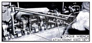
1951 Buick Cylinder Head Bolt Wrenches
Tighten 1951 Buick cylinder head bolts to 65-70 ft. lbs. torque following the sequence shown in figure 2-17.
1951 Buick Cylinder Head Bolt Tightening Sequence
After installation of 1951 Buick cylinder head, particularly with the crimped steel gasket, tighten all bolts a little at a time in proper sequence about three times around before final tightening to 65-70 ft. lbs. torque. After the engine has been warmed up to operating temperature, recheck bolts and adjust torque as required.
Adjust valve lash (par. 2-14) or make initial adjustment of hydraulic valve lifters (par. 2-15).
Replacement of 1951 Buick Rocker Arm Cover Gasket
Before a new gasket is installed, scrape off all pieces of old gasket from 1951 Buick cylinder head, wash machined surface with suitable solvent and wipe it dry.
The valve rocker arm cover gasket should be cemented to the 1951 Buick cylinder head instead of the cover. When gasket is cemented to the cover it is more easily damaged when removing or installing cover.
Apply a heavy coat of thick gasket shellac or cement to gasket surface of 1951 Buick cylinder head, allow it to dry until quite tacky, then press gasket down evenly and in proper position on 1951 Buick cylinder head. Install rocker arm cover to hold gasket in place until cement is thoroughly dry.
2-17 RECONDITIONING VALVES
Cleaning, Refacing and Reseating Valves
After removal of valves and springs from 1951 Buick cylinder head, scrape all carbon from combustion chambers and valves. If wire brushes are used for cleaning carbon, use care to avoid scratching valve seats and valve faces. Clean all carbon and gum deposits from valve guides.
Valve faces and valve seats must not be cut away excessively when using refacing and reseating equipment. Only enough metal should be removed to true up the surfaces and remove pits.
The valve head will run hotter as its thickness is decreased. If valve head must be ground until the outer edge is sharp in order to clean up the face, the valve should be discarded because the sharp edge will run too hot.
Cutting a valve seat results in lowering the valve spring pressure and increases the width of the seat. The nominal width of a valve seat is .062″ (1 1/6″). If valve seat is over5/64′ wide after truing, it should be narrowed by using the proper 20 degree and 70 degree cutters.
The refacing and reseating operations should leave the refinished surfaces smooth and true so that a minimum of lapping with grinding compound is required. Excessive lapping will groove the valve face and a grooved valve will not seat tightly.
Valves usually are tested after refacing and seating by lightly coating the valve face with prussian blue and turning the valve against its seat. This indicates whether the seat is concentric with the valve guide but does not prove that valve face is concentric with the valve stem, or that the valve is seating all the way around. After making this test, wash all blue from surfaces, lightly coat valve seat with blue and repeat the test to see whether a full mark is obtained on the valve. Both tests are necessary to prove that a proper seat is being obtained.
Replacement of Valve Stem Guides
If valve stem guides are worn to the extent that replacement is necessary, drive old guides out with Remover and Replacer J 269. When a new guide is driven into place from top side of 1951 Buick cylinder head the upper end of guide must extend 1 5/32″ above the top surface of 1951 Buick cylinder head.
Replacement guides must be finish reamed after installation in 1951 Buick cylinder head. Use Valve Guide Reamer J 129-3 to provide .374″ to .375″ finished size in both inlet and exhaust guides.
The clearance between inlet valve stem and guide is .0015″ to .0035″ (.0025″ desired). The clearance between exhaust valve stem and guide is .0021″ to .0039″ (.003″ desired). The inlet and exhaust valve stems are ground to proper diameters to provide the different clearances in guides of the same reamed size.
After valve guides have been reamed to size, true up valve seats so they are concentric with guides and test for proper seating of valves (subpar. a, above).
Correct Assembly of Rocker Arms, Springs, Brackets and Shaft
The rocker arms are mounted on a tubular steel shaft which is supported upon the 1951 Buick cylinder head by eight brackets attached by bolts and studs. Springs placed around the shaft between adjacent rocker arms hold the arms in position against the brackets. The rocker arm at each end of shaft is held against the bracket by two flat washers with a spring washer between, and a cotter pin. The shaft is prevented from turning by a pilot screw in the second bracket. See figures 2-18 and 2-19.
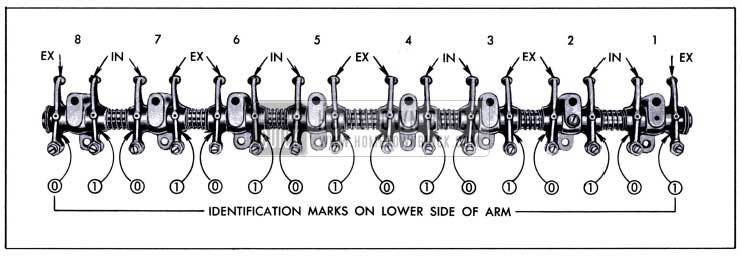
1951 Buick Rocker Arms, Shaft and Brackets-Series 40-50
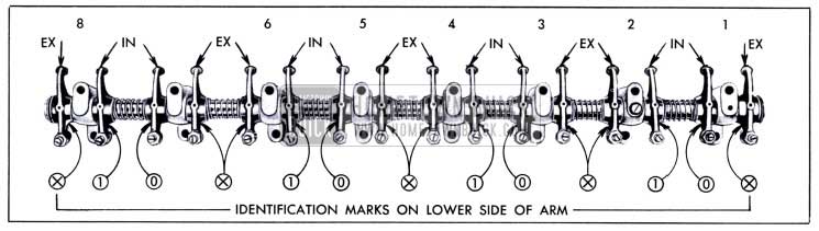
1951 Buick Rocker Arms, Shaft and Brackets-Series 70
Two different valve rocker arms are used on each Series 40-50 engine, differing only in the angle at which the arms extend from the shaft. Both rocker arms are offset, meaning that arms extend at an angle other than 90 degrees to centerline of shaft. Two different offset rocker arms are used for inlet valves on Series 70 engines, and a third straight (90 deg.) rocker arm is used for all exhaust valves.
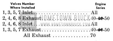
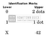
To identify each rocker arm and assist in installation, an identification mark is formed in the lower side of bearing boss, and identification depressions or dots, or a number, also are formed in upper side of bearing boss as follows:

1951 Buick Rocker Arm Identification Marks
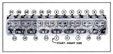
1951 Buick Valve Numbers
Figures 2-18 and 2-19 shows the proper position of each valve rocker arm according to the lower identification mark.
2-18 CHECKING 1951 BUICK VALVE AND CAMSHAFT TIMING
A timing chain will usually become noticeably noisy at idle speed before it has worn to the extent that valve timing is changed enough to noticeably affect engine performance. When it becomes desirable to check valve timing to determine whether the chain has been correctly installed, it may be done in the following manner.
Checking Timing on Engine Having Adjustable Valve Lash
- Adjust valves for .015″ road operating lash (par. 2-14), stop engine and turn until either No.2 or No.7 exhaust valve is fully closed.
- Mounting dial indicator to bear against the valve spring cap of the fully closed exhaust valve and set indicator at zero. See figure 2-20.
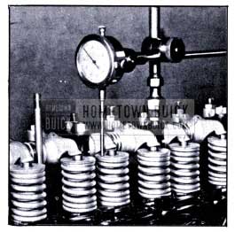
1951 Buick Dial Indicator Set to Check Valve Timing
- Slowly turn engine in running direction only until exhaust valve opens exactly .145″.
NOTE: It is advisable to remove flywheel lower housing so that engine can be turned very slowly by means of pinch bar applied to flywheel ring gear.
- Remove timing hole cover. If the “U.D.C. 1-8” mark on flywheel is visible through the timing hole, the valve and camshaft timing is correct.
Checking Timing on 1951 Buick Engine Having Hydraulic Valve Lifters
- Turn engine until either No. 2 or No. 7 exhaust valve is fully closed.
- Mount dial indicator to bear against the valve spring cap of the fully closed exhaust valve and set indicator at zero. See figure 2-20.
- Loosen adjusting ball stud lock nut and tighten adjusting ball stud until indicator momentarily reads .015″, then wait until leak down in valve lifter allows indicator to return to zero.
- Repeat Step 3 until indicator fails to return to zero, indicating that valve lifter plunger is bottoming on shoulder in lifter body. While observing indicator, carefully loosen ball stud just enough to obtain zero indicator reading.
- On Series 40-50 engine, slowly turn engine in running direction only until exhaust valve opens exactly .145″. On Series 70 engine, open exhaust valve exactly .155″. NOTE: It is advisable to remove flywheel lower housing so that engine can be turned very slowly by means of pinch bar applied to flywheel ring gear.
- Remove timing hole cover. If the “U.D.C. 1-8” mark on flywheel is visible through the timing hole, the valve and camshaft timing is correct.
- After checking timing readjust ball stud and valve lifter as described in paragraph 2-15.
2-19 REPLACEMENT OF 1951 BUICK TIMING CHAIN AND CRANKSHAFT OIL SEAL
Replacement of 1951 Buick Timing Chain
- Drain cooling system and remove radiator core.
- Remove fan belt and crankshaft balancer.
- Remove timing gear cover after loosening two lower crankcase bolts on each side to avoid damage to gasket.
- Check the slack in timing chain. Initial slack in the timing chain when new allows 1/4″ to 3/4″ outward movement under finger pressure applied midway between points of contact with sprockets. Permissible slack in a worn chain can be as high as 1″ outward before it is necessary to replace the chain.
- If chain requires replacement, turn crankshaft to align timing marks on sprockets with timing marks on chain. Each sprocket has a punch mark at one space between two teeth. Two teeth on timing chain, ten links apart, are marked with copper plated washers. See figure 2-21.
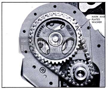
1951 Buick Timing Chain and Sprocket Marks
- Remove 1951 Buick camshaft sprocket which is attached to camshaft by a bolt, lockwasher and plain washer. The sprocket drives camshaft through a key pressed into camshaft. Remove timing chain as sprocket is removed.
- Thoroughly clean all sludge from timing gear cover and timing chain compartment. Make sure that oil drain hole to lower crankcase is clear.
- Install new timing chain with camshaft sprocket, being sure that timing marks on sprockets and chain are in line as shown in figure 2-21.
- Examine crankshaft oil seal in timing gear cover. If seal is worn or of doubtful condition install a new seal as described in subparagraph b below.
- Before installation of timing gear cover, coat rubber lip of oil seal with Standard Graphite Grease No. 4. When cover is installed make sure that the two dowel pins are in place in crankcase to properly locate cover so that the oil seal will be centered around the hub of crankshaft balancer.
- Use care when installing crankshaft balancer to avoid damage to crankshaft oil seal. Complete the installation of parts and adjust fan belt tension (par. 2-27).
Replacement of 1951 Buick Crankshaft Oil Seal
The 1951 Buick crankshaft oil seal is pressed into a recess in timing gear cover and a gasket is used to prevent leakage around the seal. See figure 2-22.
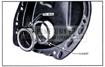
1951 Buick Crankshaft Oil Seal and Gasket
- Drive old seal out with a punch, using care not to distort timing gear cover. Remove old gasket and wipe all dirt out of recess.
- Place a new gasket in recess, and place new oil seal in position over recess, with the spring side outward.
- Drive oil seal into recess and tight against the gasket, using Oil Seal Driver J 1870. See figure 2-23.
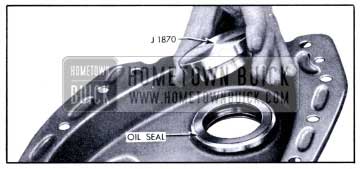
1951 Buick Installing Crankshaft Oil Seal
- Examine hub of crankshaft balancer for burrs which would damage the oil seal and for grooving from contact with oil seal. If hub is grooved, oil leakage may be expected even with a new seal. A slightly grooved hub may be refinished; however, if deeply grooved the balancer should be replaced to insure proper contact of hub with oil seal.
2-20 1951 BUICK CAMSHAFT BEARINGS AND END PLAY
The 1951 Buick camshaft is supported in five steel-backed babbitt-lined bearings which are pressed into the 1951 Buick cylinder crankcase. The camshaft bearings must be line reamed to size after being pressed into the crankcase. Since this operation requires special reaming equipment the original bearings should be retained unless severely damaged.
Slightly scored camshaft bearings will be satisfactory if the surface of camshaft journals are polished and bearings are cleaned up to remove burrs, and the fit of shaft in bearings is free and within the clearance limits of .0015″ to .004″.
Camshaft end play is controlled by a spacing ring located between the camshaft front bearing journal and a thrust plate attached to crankcase behind the camshaft sprocket. The spacing ring provides clearance or end play of .004″ to .008″ when the camshaft sprocket is tightened against it by the sprocket bolt.
IMPORTANT. When a new camshaft is installed make certain that it is the correct part for the type of valve mechanism in the engine. Use of a camshaft designed for plain sleeve lifters in an engine equipped with hydraulic valve lifters, or vice-versa, will result in extremely rough and noisy engine operation.
For identification purposes, camshafts have a 1/4″ land located between No. 6 and No. 7 valve operating cams. This land, which may be seen when lower crankcase is removed, is finished as follows:
- For Plain Sleeve Lifters-land has dark, rough-turned surface, with a 1/16″ x 1/16″ groove cut in center.
- For Hydraulic Lifters-land has a bright finish ground surface and no groove.
Leave A Comment
You must be logged in to post a comment.