SECTION 2-B 1951 BUICK ENGINE DESCRIPTION
2-4 1951 BUICK ENGINES AND MOUNTINGS
Engines in Each Series
The 8-cylinder, in-line, valve-in-head engines used in Series 40-50 and Series 70 are of the same general design and external appearance, differing principally in bore and stroke, power, and dimensions of parts. The bore, stroke, piston displacement, compression ratio and horsepower of all engines are given under Engine General Specifications (par. 2-2).
The smaller engine used in Series 40-50, designated “F 263,” differs from the larger engine used in Series 70 in having all crankshaft bearings of the same diameter from front to rear. It also differs from the larger engine in having the piston pins offset 1/16″ and the crankshaft offset 1/8″ toward the camshaft side from the centerline of the cylinder bores.
“F 263” engines have the following variations in regard to transmission and series applications:
- All Dynaflow engines use hydraulic valve lifters which do not require valve lash adjustment.
- Series 50 synchromesh engines use hydraulic valve lifters.
- Series 40 synchromesh engines use plain sleeve valve lifters with adjustable valve lash.
- All synchromesh engines use a thick Steelbestos cylinder head gasket; all Dynaflow engines use a thin steel gasket to provide a higher compression ratio.
- Synchromesh engine crankshafts, flywheels, and flywheel housings are different from the Dynaflow engine parts (see par. 2-5 d).
Series 70 engines do not have any variations since only the Dynaflow transmission is used in this series. These engines are equipped with hydraulic valve lifters.
Engine and Transmission Mountings
The engine and transmission assembly is supported at three points on “Controlled Frequency” mountings. See figure 2-3.
1951 Buick Engine and Transmission Mountings
Special synthetic rubber pads having the required friction characteristics are used to provide controlled damping properties.
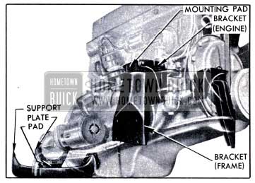
The front engine mounting pads are located on opposite sides of the engine near the center, fore and aft, and approximately midway between top and bottom of the cylinder crankcase. The mounting pads are fastened between engine mounting brackets extending upward from the car frame and brackets extending outward from the crankcase. The front mountings are designed to support the weight of the engine and control its torsional characteristics.
The rear (transmission) mounting is composed of two parts; a mounting pad to support a portion of the weight of engine and transmission assembly, and a thrust pad to take the drive thrust from the rear wheels. The mounting pad is located between the transmission rear bearing retainer and the transmission support on car frame. The thrust pad is located between the rear edge of transmission support and a thrust plate extending downward from the rear end of transmission rear bearing retainer. Steel shims are used to take up all clearance between the thrust pad and transmission support.
2-5 1951 BUICK ENGINE CONSTRUCTION
Cylinder Crankcase, Cylinder Head and Gaskets
The cylinder block and crankcase are cast integral to form the cylinder crankcase. This construction, together with liberal reinforcing ribs also cast integral, provides maximum rigidity with a minimum size and weight.
The cylinders are precision bored and double honed. The honing operations are controlled to leave minute pockets in the cylinder walls which are, in effect, small oil reservoirs which provide efficient piston lubrication.
When one or more bores in a cylinder crankcase cannot be properly finished to the nominal size, all bores are finished to .010″ oversize and are fitted with a .010″ oversize pistons and rings. This practice is quite general in the automotive industry and engines having such cylinder crankcases are not to be considered as special or other than production standard. These engines are identified for service purposes by a dash mark about 1/4″ long stamped directly following the engine number.
The detachable one-piece cast iron cylinder head contains the combustion chambers which are cast in place. The cylinder head mounts the overhead valve mechanism, spark plugs, intake and exhaust manifolds, and is attached to the cylinder crankcase by alloy steel bolts.
The Series 70 engine, and the Series 40-50 engines used with synchromesh transmissions have steelbestos cylinder head gaskets approximately .050″ thick, Series 40-50 engines used with Dynaflow Drive have sheet steel gaskets – .015″ thick. To insure a tight seal, the steel gasket is crimped around the edges of all openings where leakage may occur.
Pistons, Pins, and Rings
Pistons are Anodized aluminum alloy. All pistons have full skirts, are cam ground, and have four piston rings above the piston pin, Series 40-50 aluminum pistons have two transverse slots in bottom ring groove; Series 70 pistons have slots in skirt below bottom ring groove. All Series 40-50 pistons have the pins offset 1/16″ toward camshaft side; Series 70 pins are on centerline of piston. See figure 2-4.
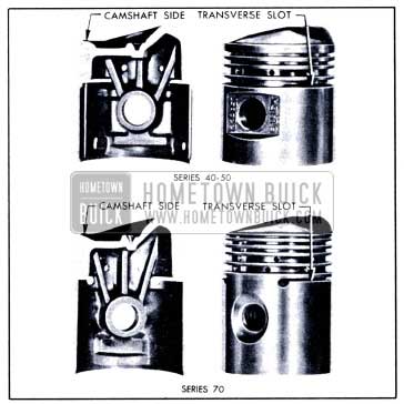
1951 Buick Series 40-50 and Series 70 Pistons
Two bosses cast inside the piston skirt below piston pin bosses provide points at which metal is removed as required during production in order to bring the piston within the specified weight limit. Standard and oversize pistons are held to the same weight limit so that engine balance is not affected by installation of one or more oversize pistons.
The piston pin bosses are diamond bored to form bearings for the piston pins. The piston pins float in the pistons and are held stationary in connecting rods by clamp bolts. A notch is ground at the middle of each pin for the clamp bolt, and the pin is solid at this point to prevent distortion.
The piston head is specially shaped with a hump on one side and a rounded depression on the camshaft side. This unusual shape combined with the valve-in-head design forms a combustion chamber in which the fuel-air charge is compressed in the form of a flattened ball at the point of ignition. This “Fireball” design regulates the burning of the fuel-air charge and smooths out the power impulses. See figure 2-4.
The compression rings in the two upper grooves of piston are distinguished by a small groove (on some rings a bevel) cut around the inner edge on one side. This groove (or bevel), which must be on top side of ring when installed, permits the ring to warp very slightly in the groove so that only the lower outer edge contacts the cylinder wall to aid in controlling oil during light duty operation. Under heavy duty operation the force of explosion flattens the ring and pushes it outward to provide heavier contact with the cylinder wall and insure an effective compression seal. See figure 2-5.
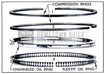
1951 Buick Piston Rings
The ring used in the third groove from top of piston is a conventional channeled type oil ring with oil return slots cuts through the channeled section. Oil passing through these slots returns to the crankcase through holes drilled in the piston. The narrow lands on this ring provide oil control and permit rapid wear in during the break-in period.
The ring used in the fourth groove from top of piston is designated as the “Flex-Fit” oil ring. The name was derived from the shape of the ring and its extreme flexibility. The ring is made from strip steel and is composed of segments which are joined at the inner edge of ring and separated by narrow slots in the wiping edges. This flexible construction permits perfect contact between the piston ring and the cylinder wall. Oil passing through the inner slots returns to the crankcase through holes drilled in the piston in Series 70, or through the transverse slots in Series 40-50.
The compression rings and the “Flex-Fit” rings are coated to aid in the seating of the rings and diminish the possibility of any scuffing or unnecessary wear during the break-in period.
Connecting Rods
Connecting rods are heat-treated steel drop forgings of 1-beam section. Rods are forged with sufficient metal on bosses at both ends so that metal can be removed as required to secure correct weight and balance during manufacture.
The upper boss of connecting rod is bored, slotted, and tapped to receive and clamp the piston pin. The lower end and cap of rod are accurately machined to receive the bearings. No shims are used between rod and cap as bearings are precision bored and replaceable.
The cap is attached to the rod with two special diameter ground bolts to insure correct alignment; bolts are provided with hex nuts and pal nuts. A small oil hole is drilled through the bearing and flange of rod to provide lubrication to cylinder walls on the heavy thrust (camshaft) side.
Crankshaft, Bearings, Flywheel and Balancer
The crankshaft is counterbalanced by weights forged integral with crank cheeks, and is both statically and dynamically balanced during manufacture. A flange forged integral with rear end of shaft supports the flywheel which is separately balanced during manufacture.
The crankshaft in engines used with Dynaflow Drive are not interchangeable with crankshafts in engines used with synchromesh transmission. The difference is in the shape of the flywheel flange and the counterbore in rear end of shaft.
The crankshaft is supported in the cylinder crankcase by five bearings. In Series 70 engines the crankshaft journals and the bearings are stepped up in diameter, from front to rear. In Series 40-50 engines the journals and bearings are the same diameter from front to rear.
Full precision crankshaft bearings are used in all engines. The bearings are made from Durex-A material having superior fatigue qualities. The babbitt lining is bonded to the steel back of the bearing by a fine textured nickelcopper matrix which gives continuous support to the bearing metal. No shims or other means of adjustment are required with these bearings as they are held to very close limits on size.
Flywheels used with synchromesh transmission are cast iron, machined to form a driving face for the clutch plate. Flywheels used with the Dynaflow transmission are flexible steel stampings to which the converter primary pump is bolted. Both type flywheels carry a ring gear for cranking the engine.
A flywheel type harmonic balancer is mounted on the front end of crankshaft to dampen torsional vibration. The hub of the balancer is keyed to the crankshaft and retained by a clamp bolt threaded into the end of crankshaft. A pulley incorporated in the balancer assembly drives the fan, water pump, and generator through a belt.
Camshaft and Valve Mechanism
The forged steel camshaft is supported in the cylinder crankcase in five steel-backed babbitt-lined bearings and is driven from the crankshaft by a silent chain. The camshaft actuates the overhead valves through lifters, push rods, and rocker arms.
The valve lifters operate in guide holes reamed in crankcase above the camshaft. Series 40 synchromesh engines use plain sleeve type valve lifters, and the ball studs in rocker arms are used to adjust valve lash to specified limits to insure full seating and quiet operation of valves. Series 40 Dynaflow and all Series 50-70 engines use the self-adjusting hydraulic valve lifters described in subparagraph f below.
The upper and lower ends of each push rod have centrally drilled oil holes, and the upper end is counterbored to form a shroud around a bleed hole drilled in the push rod tube. The bleed hole permits air and surplus oil to escape from the push rod, thus eliminating air locking and preventing excessive build up of oil pressure which would result in an over-supply of oil to the valve stems.
The rocker arms pivot on a tubular steel shaft which is supported on the cylinder head by eight brackets. An oil passage drilled between the bearing and the threaded ball stud hole connects with a groove and oil holes in the ball stud, through which oil is conducted to the push rod socket and interior of push rod. See figure 2-6.
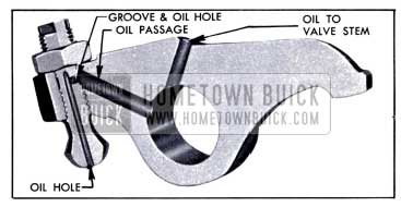
1951 Buick Oil Passages in Rocker Arms and Ball Studs
Inlet valves have streamlined heads and exhaust valves have mushroom heads, all ground for 45 degree seats in cylinder head. Each valve is closed by two coil springs.
Hydraulic Valve Lifters
Series 40Dynaflow and all Series 50-70 engines use hydraulic valve lifters which automatically maintain zero valve lash under all operating conditions. The ball studs in rocker arms are used only for the initial adjustment of the hydraulic lifters at time of installation. A label is placed on the rocker arm cover, stating-“This Engine Equipped With Hydraulic Lifters.”
The construction of a hydraulic valve lifter is shown in figure 2-7.
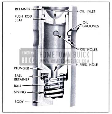
1951 Buick Hydraulic Valve Lifter, with Quarter Section Cut Out
The plunger and the body are ground to very close limits and are selectively fitted to obtain free movement with the least possible clearance, in order to control leakage of oil from the lower chamber within very close limits. The spring exerts a 10 pound load, which is enough to take up all lash clearances between parts in the valve train without affecting positive seating of the valve. The check valve ball seats in the plunger feed hole and the retainer limits its travel to .004″-.008″.
In operation, the plunger and lower chamber are kept filled with oil, being supplied through passages in the rocker arm shaft, rocker arm, ball stud, push rod ends, and the push rod seat in lifter. The tubular push rod serves as a reservoir to maintain a head of oil above the lifter.
When the valve lifter is on the camshaft base circle (off the cam) the spring raises the plunger to eliminate all lash clearances between parts in the valve train. If the lower chamber is not completely filled with oil at this time, oil will run down through the feed hole past the check valve ball to fill the chamber.
As the rotating camshaft raises the lifter body the pressure created in the lower chamber closes the check valve so that the plunger and push rod seat move with the body. This movement is transmitted to the push rod, rocker arm, and valve without lost motion. During the lifting movement any oil that leaks past the plunger returns to plunger or passes out of the body through grooves and holes in these parts. When the parts in valve train expand du e to heat, the volume of oil in lower chamber of lifter is automatically adjusted through the check valve to compensate for these changes and maintain zero valve lash.
2-6 1951 BUICK ENGINE LUBRICATION SYSTEM
The engine lubrication system is of the force-feed type in which oil is supplied under full pressure to crankshaft, connecting rod, and camshaft bearings, and is supplied under controlled volume to the rocker arm bearings, push rods, and valve lifters. All other moving parts are lubricated by gravity flow or splash. See figure 2-8.
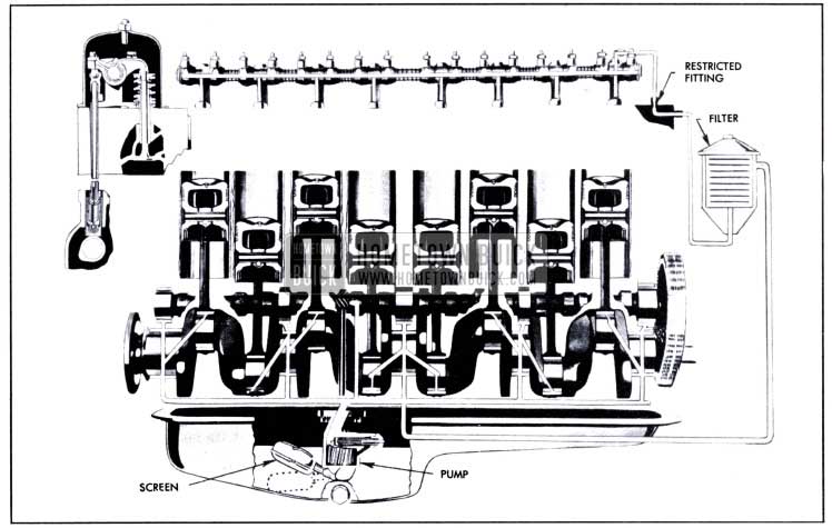
1951 Buick Engine Lubrication System
The supply of oil is carried in the lower crankcase, which is filled through the opening in the rocker arm cover. The filler opening is covered by a combination filler and ventilating cap which contains filtering material to exclude dust. A removable oil gauge rod on right side of crankcase is provided for checking oil level.
Oil in lower crankcase is picked up and circulated by a gear type oil pump. The oil pump inlet is equipped with a floating screen which is hinged so that it follows the oil level under all conditions, thus drawing clean oil from near the top above any sediment which might collect at bottom of crankcase. See figure 2-8. Should the oil pump screen become clogged due to abnormally thick oil, sludge, or other cause, suction of the pump will ca u se the screen to collapse at its center and open a valve that will permit oil to be drawn into the pump.
The oil pump is driven by the distributor shaft which is driven from the camshaft through spiral gears. It contains two helical gears enclosed in the pump body and retained by the oil pump cover, to which the floating oil pump screen is attached. The oil pump body contains a non-adjustable spring loaded pressure valve, which regulates the oil pressure at 3G pounds at 35 MPH under normal operation.
Oil under pressure l eaves the pump through a drilled passage in pump body, which connects to the main oil gallery in the right side of crankcase. Branch passages in the crankcase distribute oil from the oil gallery to the camshaft and crankshaft bearings. Holes drilled in the crankshaft carry oil to the connecting rod bearings.
Pistons and cylinder walls are lubricated by oil forced through a small hole in the lower end of each connecting rod, which registers with the hole in crankshaft once in each revolution. Piston pins are lubricated by splash.
The timing chain and sprockets are supplied with oil through a small passage which connects the main oil gallery with a recess and drilled hole in the camshaft thrust plate. The hole through the thrust plate is blocked by the camshaft sprocket hub except when a slot in hub registers with the hole once in every revolution of the camshaft, at which time oil is thrown into the inside area of sprocket. Three holes in the camshaft sprocket allow oil to pass to the timing chain. See figure 2-8.
All oil supplied to the overhead valve mechanism is filtered by passing it through an AC oil filter containing a folder paper low-restriction element. The oil filter is mounted on a bracket attached to thermostat housing above the water pump. The inlet side of filter is connected by a pipe to the main oil gallery in right side of crankcase. The outlet side of filter is connected by a pipe to a drilled passage in cylinder head. The filter contains a valve which will open at 7-9 pounds pressure to by-pass oil to the outlet in case the filter element becomes plugged or otherwise inoperative.
A short pipe under the rocker arm cover connects the drilled passage in cylinder head to the top of No. 1 rocker arm shaft bracket, through which oil is fed into the hollow rocker arm shaft. The upper pipe fitting in cylinder head has a restricted opening to control the volume of oil supplied to the rocker arm shaft. Holes in the shaft feed oil to each rocker arm bearing.
A small hole in each rocker arm feeds a slight amount of oil to the contact point between the arm and the valve stem. Another passage conducts oil to the ball stud, where it connects with a groove and oil holes in stud through which oil is fed to the push rod. See figure 2-6. On all engines having hydraulic valve lifters, the push rod ends have holes through which oil is fed into the push rods and down into the valve lifters.
On Series 40 having adjustable valve lash the hole in push rod upper end is eliminated so that oil does not enter the push rod. The rod end socket is deeper to form a shroud that prevents oil from spraying over valve stems. These rod ends are copper finished for identification. To reduce rocker arm shaft oil pressure, the oil inlet pipe is reduced in size to fit loosely in No. 1 bracket oil hole and thus permit oil to bleed out at this point. A baffle is located above the loose joint to direct surplus oil downward and away from valve stems.
The ignition distributor gears are given positive lubrication by means of an oil passage in the crankcase running from the main oil gallery to a point in the distributor housing from which oil flows over the gears.
2-7 1951 BUICK CRANKCASE VENTILATION SYSTEM
A crankcase ventilator inlet, containing a gauze filter element, and an outlet suction pipe are used to provide crankcase ventilation. Ventilation of the crankcase is accomplished by the vacuum created by the outlet pipe.
The outlet pipe is connected to the push rod cover, and extends rearward at a low level on right side of engine. Suction created by air passing the open end of the outlet pipe, when car is moving forward, causes air to be drawn into the rocker arm cover through a ventilating type oil filler cap which contains a gauze filtering element. The ventilating streams of air are drawn out of crankcase and rocker arm cover through the push rod compartment and outlet pipe. See figure 2-9.
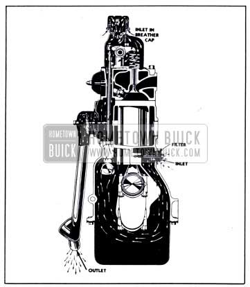
1951 Buick Crankcase Ventilation-Section View
The air passing through the crankcase, push rod compartment, and rocker arm cover picks up fuel and water vapors and removes them from the engine. The ventilating system does not remove all fuel dilution in cold weather as a small amount is advantageous in low temperature operation. It does, however, prevent an accumulation of more than 20 % fuel dilution and removes all water under average driving conditions.
2-8 1951 BUICK ENGINE COOLING SYSTEM
The engine water cooling system is the pressure type, with thermostatic water temperature control and water pump circulation. A fan located behind the radiator provides air circulation.
The cooling system is sealed by a pressure type radiator filler cap which causes the system to operate at higher than atmospheric pressure. The higher pressure raises the boiling point of coolant and increases the cooling efficiency of the radiator. The seven pound pressure cap used on all series permits a possible increase of approximately 20°F in boiling point of coolant.
The pressure type radiator filler cap contains a blow off or pressure valve and a vacuum or atmospheric valve. See figure 2-10.
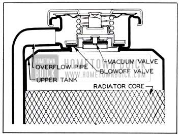
1951 Buick Pressure Type Radiator Cap Installation
The pressure valve is held against its seat by a spring of predetermined strength which protects the radiator by relieving the pressure if an extreme case of internal pressure should exceed that for which the cooling system is designed. The vacuum valve is held against its seat by a light spring which permits opening of the valve to relieve vacuum created in the system when it cools off and which otherwise might cause the radiator to collapse.
The thermostatically operated by-pass type of water temperature control permits the engine to reach its normal operating temperature quickly, by causing the water pump to circulate coolant through the engine, but not through the radiator during the warm-up period. This is accomplished by a thermostat valve located in the cylinder head water outlet, and a fixed by-pass passage located between the water outlet and the water pump inlet. See figures 2-11 and 2-12.
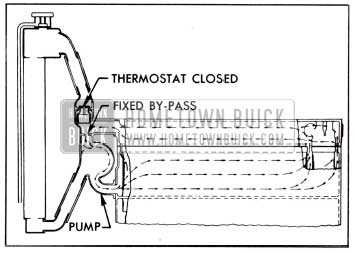
1951 Buick Recirculation-Thermostat Closed
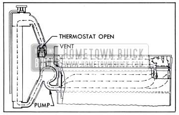
1951 Buick Normal Circulation-Thermostat Open
When the coolant is below normal operating temperature the thermostat valve closes and blocks circulation through the radiator. The water pump pressure forces the coolant through the by-pass passages to recirculate through the cylinder block and head. See figure 2-11. When the coolant in cylinder block and head reaches the proper temperature the thermostat valve starts to open and the circulation proceeds through the radiator in the normal way. At normal operating temperatures the thermostat is fully open. See figure 2-12.
Water entering the cylinder block water jacket from the pump moves to the rear end of the block before flowing upward into the cylinder head water jacket and thence forward to the radiator. This path of circulation provides maximum and uniform flow of coolant over all water jacketed surfaces.
A small vent passage is located forward of number one cylinder to permit any steam forming in the cylinder block water jacket to escape into the cylinder head water jacket. See figure 2-12.
The coolant is circulated by a heavy duty centrifugal water pump mounted on the front end of the cylinder crankcase. The fan and pulley are mounted on the outer end of the pump shaft so that the pump and fan are driven by a belt from a pulley on the crankshaft. The pump shaft is incorporated in a double-row ball bearing which is sealed at both ends to exclude dirt and water and is lubricated during manufacture so that no further lubrication is required. The pump is sealed against leakage by a packless non-adjustable seal assembly mounted in the pump body in position to bear against the hub of impeller. See figure 2-13.
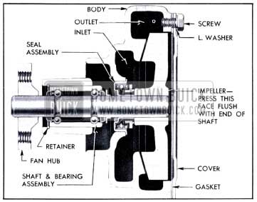
1951 Buick Sectional View of Water Pump
The seal assembly is composed of a brass sleeve, a helical spring, a rubber bellows, and a carbon washer. The brass sleeve is pressed into the hub of pump body. The spring presses the flanged ends of the rubber bellows against the sleeve and the carbon washer, and also presses the carbon washer against the hub of impeller to seal against passage of water. See figure 2-13. Two ridges pressed in the brass sleeve engage notches in the carbon washer to prevent the washer from turning with the impeller.
All series are equipped with Harrison V-type cellular radiator cores having copper water passages and copper cooling fins. Radiator thickness, frontal area, and cooling system capacity are given in paragraph 2-2 (g).
A thermo-gauge to indicate temperature of coolant is mounted on instrument panel. The gauge assembly includes a capillary tube with a bulb which attaches to the cylinder head so as to extend into the water jacket.
Leave A Comment
You must be logged in to post a comment.