SECTION 10-J 1951 BUICK WIRING CIRCUIT DIAGRAMS
10-69 1951 BUICK CIRCUIT DIAGRAMS, INSPECTION HOLE, AND FUSE BLOCK
This Section contains all the necessary 1951 Buick wiring circuit diagrams for chassis and body. The 1951 Buick wiring may be easily traced by paying attention to the color code on each wire and the color code indicated on the diagrams.
Many of the 1951 Buick wiring connections use a push-pull type terminal. The terminal plug on the wire requires a hard push to seat it in the socket. A hard steady pull on the wire is required to detach the terminal plug from the socket. If an exceptionally hard pull is required, it is advisable to start the terminal plug by prying against the rim with a screwdriver.
An inspection hole is located in the left side of dash panel. The cover, which is attached by screws, may be quickly removed for inspection and for working on the wiring connections to instruments on forward side of instrument panel.
A central fuse block is mounted under the cowl near the steering column and to rear of the inspection hole in cowl. It is not necessary, however, to remove the inspection hole cover to replace a fuse or to disconnect wires. The fuse block serves as a convenient junction point for a number of wiring circuits, provides a mounting for the direction signal flasher, and contains the fuses shown in figure 10-109.
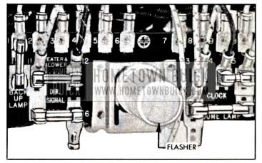
1951 Buick Fuse Block, With Direction Signals
The “Direction Signal” fuse also protects the stop light circuits. The “Dome Lamp” fuse also protects the luggage compartment and glove box lamp circuits.
CHASSIS 1951 BUICK WIRING DIAGRAMS
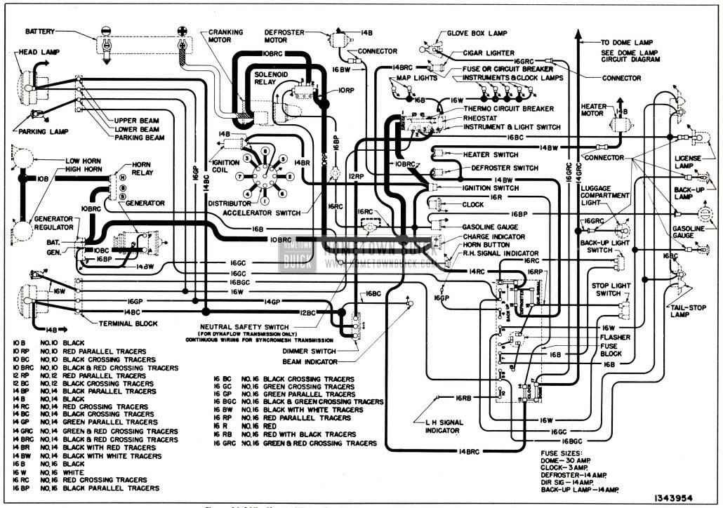
1951 Buick Chassis Wiring Circuit Diagram-Series 40 Without Direction Signals
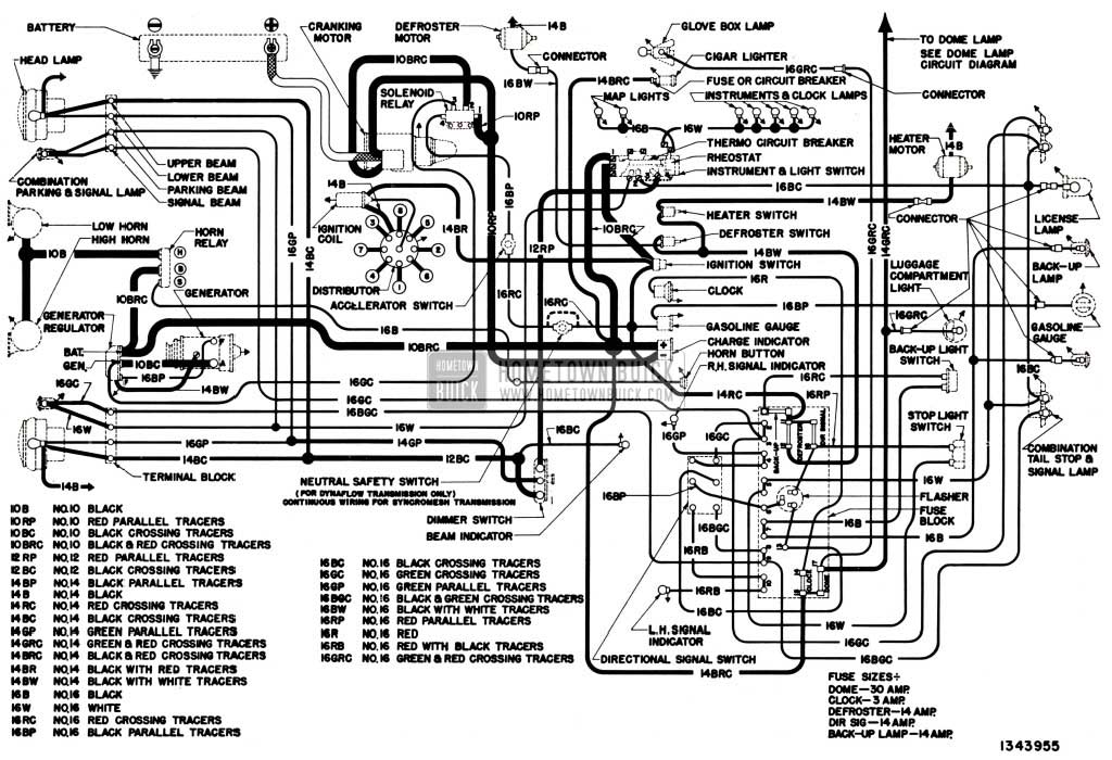
1951 Buick Chassis Wiring Circuit Diagram-Series 40 With Direction Signals
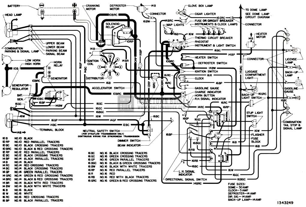
1951 Buick Chassis Wiring Circuit Diagram-Series 50-70
DOME LAMP 1951 BUICK WIRING CIRCUIT DIAGRAMS
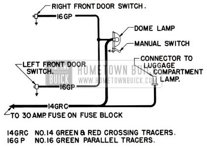
1951 Buick Dome Lamp Wiring Circuit Diagram-Series 40
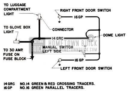
1951 Buick Dome Lamp Wiring Circuit Diagram-Models 51, 56C, 56R. 565, 76C, 76R
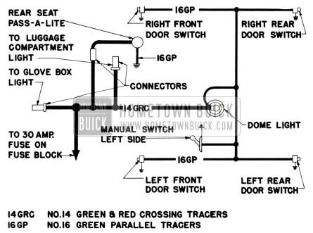
1951 Buick Dome Lamp Wiring Circuit Diagram-Models 52 and 72R
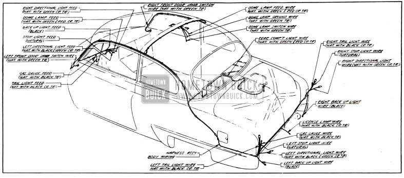
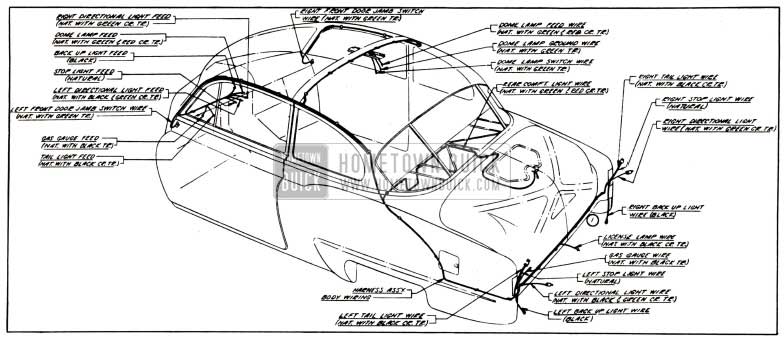
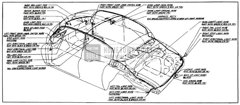
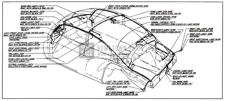
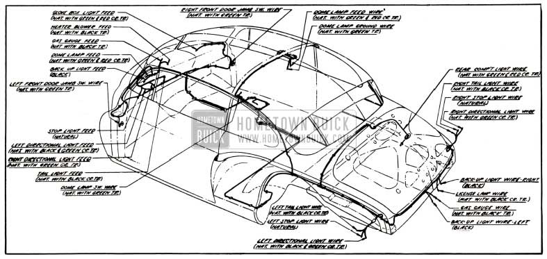
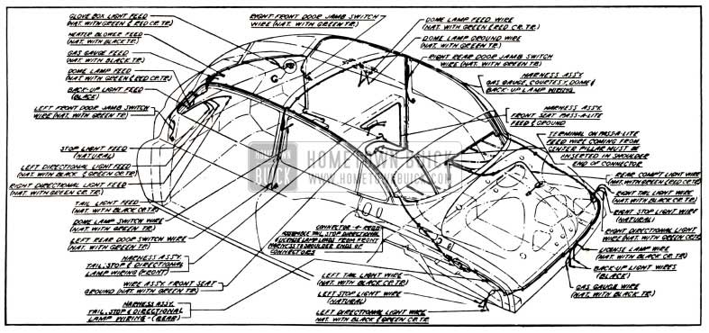
BODY 1951 BUICK WIRING DIAGRAMS
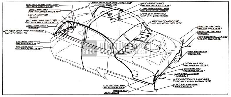
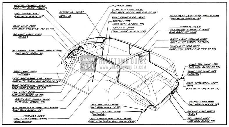
1951 Buick Body Wiring Circuit Diagram-Models 41, 41D-Styles 4369, 4369D
1951 Buick Body Wiring Circuit Diagram-Models 46, 46S-Styles 4327B, 4327
1951 Buick Body Wiring Circuit Diagram-Models 48, 48D-Styles 4311, 4311D
1951 Buick Body Wiring Circuit Diagram-Model 51-Styles 4569
1951 Buick Body Wiring Circuit Diagram-Model 56S-Style 4507
1951 Buick Body Wiring Circuit Diagram-Model 56R-Style 4537
1951 Buick Body Wiring Circuit Diagram-Models 52, 72R-Styles 4519, 4719
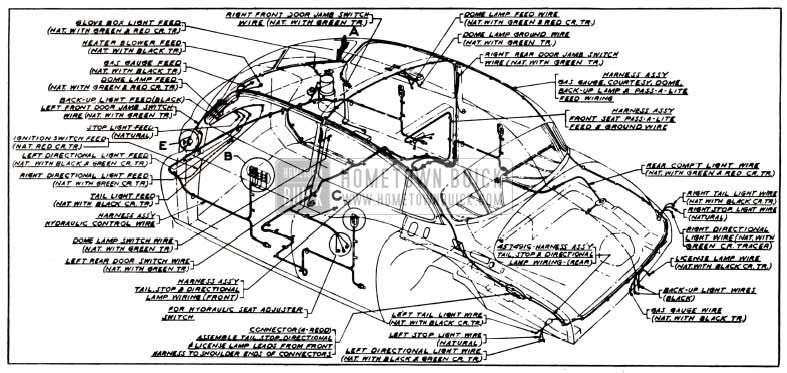
1951 Buick Body and Hydro-Lectric Wiring Circuit Diagram-Models 52, 72R-Styles 4519X, 4719X
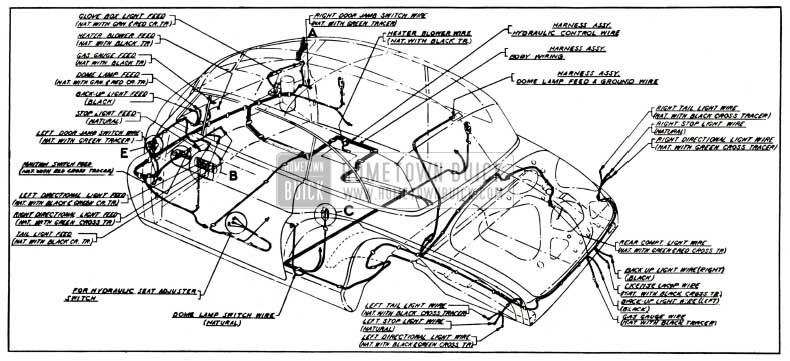
1951 Buick Body and Hydro-Lectric Wiring Circuit Diagram-Models 56C, 76C-Styles 4567X, 4767X
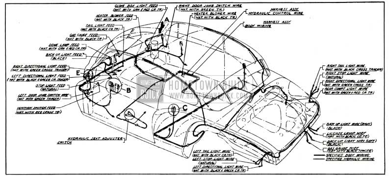
1951 Buick Body and Hydro-Lectric Wiring Circuit Diagram-Model 76R-Style 4737X
1951 Buick Body Wiring Circuit Diagram-Models 59, 79-Styles 4581, 4781
Leave A Comment
You must be logged in to post a comment.