SECTION 3-C 1951 BUICK FUEL SYSTEM ADJUSTMENTS AND REPLACEMENTS – EXCEPT IN PUMP AND CARBURETOR ASSEMBLIES
3-7 1951 BUICK AIR CLEANER AND GAS FILTER SERVICE
1951 Buick Air Cleaner Service
A 1951 Buick air cleaner with a dirty element, or with oil that is dirty, too heavy, or too high in the sump, will restrict the air flow to the carburetor and cause a rich mixture at all speeds. The device will not properly remove dirt from the air and the dirt entering the engine will cause abnormal formation of carbon, sticking valves, and wear of piston rings and cylinder bores.
Regular cleaning of the element and sump and filling sump with clean oil at 5000-mile intervals, or more frequently in dusty territory, is necessary to prevent excessive engine wear and abnormal fuel consumption. The procedure for cleaning and refilling the air cleaner is given under Lubricare Instructions, paragraph 1-2.
Cleaning 1951 Buick Fuel Pump Gasoline Filter
The bowl and strainer on the lower end of 1951 Buick fuel pump collects dirt and water which should be cleaned out periodically, at least twice a year.
- Use Z-shaped Wrench KMO 655 to remove screw and gasket then remove bowl, gasket, and strainer from lower end of fuel pump. See figure 3-6.
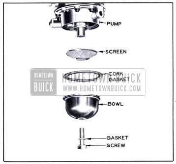
1951 Buick Fuel Pump Gasoline Filter-Disassembled
- Wash strainer and sediment bowl in Bendix Metalclene or its equivalent, to remove all traces of dirt and gum, then rinse in kerosene, distillate, or white gasoline. Gently blow through strainer with air hose.
- Use new bowl and screw gaskets when reinstalling strainer and bowl, to insure against gasoline leakage. Tighten bowl screw securely.
Cleaning 1951 Buick Gasoline Filter
The 1951 Buick gasoline filter located at carburetor inlet collects dirt and water. The drain plug at the bottom of the inlet side of filter should be removed occasionally to drain out the accumulation of dirt and water. See figure 3-7.
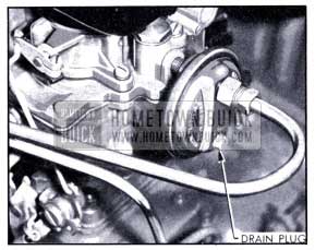
1951 Buick Moraine Gasoline Filter
When a thorough cleaning is required, remove the filter, remove the drain plug and agitate the filter in Bendix Metaclene or its equivalent. Direct air stream through the outlet port of filter to force dirt from the inlet side of filtering disk. Rinse filter in kerosene, distillate, or white gasoline and again direct air stream through the outlet port. Install drain plug and reinstall filter.
1951 Buick Carburetor Inlet Strainer
A fine mesh strainer is located in the carburetor inlet. This strainer should seldom require cleaning because of the fuel pump filter and the gasoline filter which precede it in the gasoline supply line. This strainer should be inspected however, if fuel supply at carburetor inlet is adequate but carburetor operation indicates lack of fuel.
On 1951 Buick Carter carburetor it is necessary to remove the air horn in order to remove the strainer, which is located under a brass strainer nut in bowl cover. On Stromberg carburetor it is necessary to remove the carburetor in order to reach the strainer, which is held in the inlet port in air horn by a small wire retainer clip.
3-8 1951 BUICK THROTTLE LINKAGE ADJUSTMENT
The 1951 Buick throttle linkage must work freely and be adjusted so that the accelerator pedal can move the throttle valve smoothly from fully closed to wide open positions. When pedal is pressed down against floor mat the throttle must fully open to the throttle stop on carburetor, and the choke unloader must be operated in the wide open position. When pedal is released, the throttle must close against the throttle stop screw; on Dynaflow cars the dash pot must govern the closing to prevent stalling or rolling of the engine.
Before making the following adjustments make sure that accelerator pedal is securely fastened to floor pan and rod does not bind in hole through floor mat.
1951 Buick Throttle Linkage Adjustment – Synchromesh Transmission Cars
- Disconnect the throttle operating rod ball joint from the throttle lever and open the throttle valve to wide open position against its stop.
- While a second man presses accelerator pedal firmly against the floor mat, which must be in place, adjust the ball joint on throttle operating rod so that the screw will just enter the hole in throttle lever. On Carter Carburetor the upper hole in throttle lever is used. See figure 3-8.
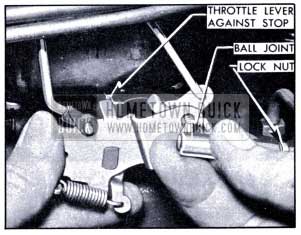
1951 Buick Throttle Rod Adjustment-Synchromesh
- Turn ball joint 1 or 2 turns farther up on rod and connect ball joint to throttle lever. Tighten lock nut. The desired adjustment is to obtain full opening of throttle valve when accelerator pedal strikes floor mat rather than having the stop on throttle lever strike hard against the boss on throttle body.
- Hold choke valve closed and check for proper operation of choke unloader when accelerator is pressed to floor mat. If choke unloader does not operate properly, adjust as described in paragraph 3-21 (Carter) or 3-28 (Stromberg).
Throttle Linkage and Dash Pot Adjustment – Dynaflow Drive Cars
- With engine hot and idling at 450 RPM, check clearance between the stop on lever at lower end of equalizer shaft and the shaft lower bracket. See figure 3-9.
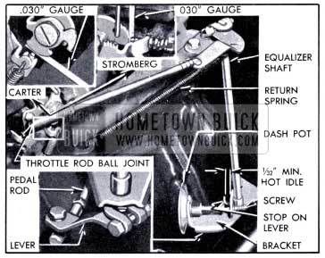
1951 Buick Throttle Linkage and Dash Pot Adjustment
If clearance is less than 1/32” adjust throttle operating rod at ball joint to obtain a minimum of 1/32″ clearance. Tighten lock nut.
- With engine shut off, check for full opening of throttle valve when accelerator pedal hits the floor mat, which must be in place. Full opening should be obtained when pedal strikes floor mat, rather than having the stop on throttle lever strike hard against the boss on throttle body. Adjust accelerator pedal rod at ball joint, if necessary to obtain full opening of throttle valve. Tighten lock nut. See figure 3-9.
- Hold choke valve closed and check for proper operation of choke unloader when accelerator pedal is pressed to floor mat. If choke unloader does not operate properly, adjust as described in paragraph 3-21 (Carter) or 3-28 (Stromberg).
- Hold choke valve closed, insert a .030″ feeler gauge between the adjustment or stop screw and the fast idle cam, then turn adjusting screw on dash pot operating lever until it just contacts the dash pot plunger button. See figure 3-9. This gives a starting setting which may require slight alteration to obtain proper dash pot control.
- With transmission in Direct Drive and brakes firmly applied, snap •throttle open to approximately 1400 RPM and immediately release accelerator pedal. If engine returns to idle too slowly, back out dash pot adjusting screw a little at a time until proper dash pot control is obtained. If engine returns to idle too fast causing engine to stall or roll, turn adjusting screw in.
- If proper control cannot be obtained by adjustment, replace dash pot.
3-9 1951 BUICK EXHAUST MANIFOLD VALVE SERVICE
Freeing up Sticking Valve
Carbon or lead salt deposits around the valve shaft may cause the valve to stick or become sluggish in operation. A valve sticking in the open position will cause slow engine warm up, excessive spitting and sluggish engine operation when cold. A valve sticking in the closed position will cause overheating, loss of power, and hard starting when the engine is hot, and may also cause warped or cracked manifolds. Sticking in either position will adversely affect fuel economy.
If the valve shaft is sticking or frozen in the valve body, free it up by tapping on the ends with a light hammer, and by rotating the counterweight. Penetrating oil or kerosene may be used to aid in freeing the shaft.
When the valve shaft is free, apply a mixture of kerosene and powdered graphite liberally to the shaft bearing; the mixture to be composed of 2% ounces of powdered graphite to 1 pint of kerosene. Lubrication of shaft every 1,000 miles is specified in Lubricare Instructions (par. 1-1).
Checking 1951 Buick Manifold Valve Thermostat Setting
The setting of the 1951 Buick exhaust manifold valve thermostat may be checked when the engine is at room temperature of approximately 70°F. Unhook the outer end of thermostat from anchor stud on the valve body and hold the valve in the closed (heat on) position. To bring the end of thermostat to the anchor stud will then require approximately 1/4 turn wind-up of the thermostat.
The thermostat is not adjustable and should never be distorted or altered in any way as this will affect its calibration. If the thermostat does not have the proper setting, or is damaged, it should be replaced.
Adjusting Valve Anti-Rattle Spring
The anti-rattle spring shown at “A” in figure 3-10 must be adjusted so that the valve cannot flutter and chatter against the inside of valve body in either the closed (heat on) or open (heat off) positions. These positions can be felt by moving the counterweight by hand, and adjustment can be made with engine hot or cold.
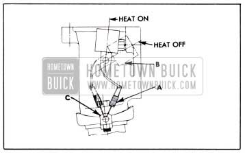
1951 Buick Valve Anti-Rattle Spring Adjustment
Bend clip “C” as required so that spring “A” will prevent the valve from contacting the valve body in either closed or open positions. Adjustment so that valve has sufficient clearance to prevent rattle in the closed position will usually be correct for the open position also. Clearance equal to 1/16″ to 1/8″ movement at the extreme end of counterweight is correct.
3-10 1951 BUICK CARBURETOR ADJUSTMENT
Do not attempt to adjust the carburetor idle needle valves until it is known that the ignition system is in proper operating condition (par. 10-44), that compression is satisfactory and valves are properly adjusted. It should also be known that the exhaust manifold valve is operating properly (par. 3-9) and that intake manifold has no air leaks, that gasoline filters and strainers are clean (par. 3-7) that fuel pump is supplying carburetor with ample fuel at specified pressure (par. 3-15), that ‘the lair supply is not restricted by the air cleaner (par. 3-7) or choke (par. 3-11) and that throttle control linkage is correctly adjusted (par. 3-8).
Any attempt to adjust or alter the carburetor to compensate for faulty conditions elsewhere in items affecting engine performance will result in reduced fuel economy an4 overall performance.
Making Initial Setting of Idle Needle Valves and Throttle Stop Screw
An initial setting of the idle needle valves is necessary to make certain that both valves are opened an equal amount. The throttle stop screw must be adjusted to provide an engine idling speed of approximately 450 RPM when hot, to prevent stalling and rough idling.
- With engine stopped, turn both idle needle valves “IN” (clockwise) until they seat lightly. CAUTION: Do not force valves against seats as this will damage valves and seats.
- On Stromberg carburetor, turn each valve “OUT” (counterclockwise) 1 1/2 turns. On Carter carburetor, turn each valve “OUT” 1 turn.
Be careful to turn both valves exactly the same amount.
- Back off throttle stop screw and hold fast idle cam in HOT (choke open) position so that throttle valves are fully closed.
- Turn throttle stop screw “IN” (clockwise) until it just contacts arm on throttle lever (Carter) or lowest step of fast idle cam (Stromberg), then turn stop screw “IN” one complete turn. This setting will give an engine idling speed of approximately 450 RPM.
Making Final Adjustment of Idle Needle Valves
The two idle needle valves and the throttle stop screw are the only external means provided for adjusting the carburetor. Turning the idle needle valves “IN” (clockwise) makes the mixture “LEAN”.
The idle needle valves control the idle or low speed system of the carburetor; all adjustments affecting the main metering or high speed system are made during assembly of the carburetor.
- With throttle stop screw and idle needle valves at the initial settings as described above, start the engine and run it until it is at normal operating temperature.
NOTE: lf the engine operates on fast idle too long after starting or else moves to slow idle too soon, or the choke unloader does not operate properly, check fast idle cam and choke unloader adjustments as described in paragraph 3-21 (Carter) or paragraph 3-28 (Stromberg).
- With engine idling at 450 RPM, turn both idle needle valves “IN” (clockwise) exactly the same amount until engine begins to roll or run unevenly.
- Carefully turn both needle valves “OUT” (counterclockwise) exactly the same amount until engine again starts to roll or run unevenly.
- Turn both needle valves “IN” one-half the distance between the first and second positions, being careful to turn both valves an equal amount. See figure 3-11.
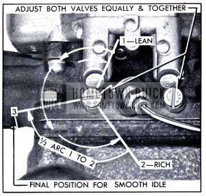
1951 Buick Adjustment for Smooth Idle
This should give the smoothest idling point. NOTE: As the needle valves are changed, the throttle stop screw also must be changed to maintain engine idling speed at 450 RPM. Use a tachometer to set engine idling speed, if available.
- If outside temperature is much colder than shop where adjustment is made, turn both needle valves “OUT” a slight amount to compensate for difference in temperature.
Final adjustment of the carburetor idle needle valves also may be made with the aid of a combustion tester, tachometer, or vacuum gauge. When such instruments are used, be sure they are in good condition and are used in accordance with the instructions of the manufacturer.
Regardless of the methods or instruments used for making adjustments in the shop, the correctness of adjustment should be finally checked by a road test for smoothness at idling speed, power on acceleration, and freedom from sluggishness or fiat spots throughout entire speed range.
When Carburetor Cannot be Adjusted for Smooth Idle
If the conditions specified at the beginning of this adjustment procedure are correct and it is not possible to obtain smooth idle operation by the specified adjustment of the idle needle valves, it may be assumed that the carburetor requires removal for cleaning and internal adjustment as described in paragraph 3-23 (Carter) or 3-29 (Stromberg).
Before removing the carburetor it is advisable to check the level of fuel in the float bowl to determine whether it is at correct height. Any deviation from the specified height will seriously affect carburetion. With engine idling at normal operating temperature, remove sight plug from float bowl and check height of fuel. On Carter and second type Stromberg carburetors, the fuel should be just high enough to wet the threads at lower side of sight hole. Second type Stromberg carburetors are distinguished from first type by having a larger sight hole boss, from which 1/16″ wide ribs extend horizontally on each side. On first type Stromberg carburetor the fuel level should be 1/32″ to 1/16″ below the lower side of sight hole.
3-11 1951 BUICK CHOKE THERMOSTAT ADJUSTMENT
The 1951 Buick choke thermostat must be correctly adjusted in order to provide good performance during engine warm-up. The correctness of the thermostat setting can be tested only when the engine is cold. The carburetor must have been properly adjusted (par. 3-10) and the manifold heat control valve must be operating properly (par. 3-9). The cold engine should start readily, idle without loading or rolling, and should accelerate smoothly during the warm-up period while the choke is in operation.
The 1951 Buick choke thermostat is calibrated to give satisfactory performance with regular blends of fuel when it is placed at the standard factory setting, as follows:
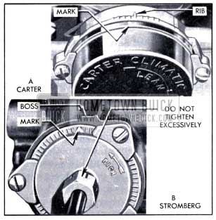
1951 Buick Carter Climatic Control
The standard factory setting is one point rich, meaning that indicator mark on thermostatic coil housing is set one graduation counterclockwise (opposite to arrow) from the large indicator rib cast on choke housing of air horn. See figure 3-12, view A.
1951 Buick Thermostat Standard Settings
1951 Buick Stromberg Choke
The standard factory setting is with the “V” index mark on thermostat cover in line with end of indicator boss on choke housing of air horn. See figure 3-12, view B.
When 1951 Buick choke thermostat is cold and throttle is opened to release the fast idle cam, the thermostat should move choke valve to fully closed position.
When it is necessary to adjust the thermostat loosen the housing or cover attaching screws and turn as required. On Stromberg choke it is also necessary to loosen the heat pipe connection to turn the cover. When tightening heat pipe connection after adjustment do not use excessive pressure, which may change position of thermostat cover.
Thermostat settings other than standard should be used only when the car is habitually operated on special blends of fuel which do not give satisfactory warm-up performance with the standard setting. A “Lean” setting may be required with highly volatile fuel which produces excessive loading or rolling of engine on warm-up with the standard thermostat setting. A “Rich” setting should be used only when excessive spitting occurs on engine warm-up with the standard thermostat setting. When making either a “Lean” or “Rich” setting, change one point at a time and test results with engine cold, until the desired performance is obtained.
3-12 REPLACEMENT OF 1951 BUICK INTAKE AND EXHAUST MANIFOLDS
When working on 1951 Buick intake and exhaust manifolds it must be understood that both manifolds must be attached to the valve body and to the 1951 Buick cylinder head in such manner that slippage can take place at the joints to compensate for differences in rate of expansion and contraction of the several parts due to heat. This is necessary because the parts do not have the same temperature under all operating conditions.
The assembly and method of attachment of these parts have been designed to avoid leakage of joints while permitting the required slippage. If attaching bolts and nuts are not tightened in proper sequence or are tightened excessively, warpage, leaking joints or cracked manifolds will result.
When leakage occurs at manifold joint the condition can usually be corrected by proper adjustment of bolts and stud nuts without removing or replacing parts. Do not attempt correction by simply tightening bolts or nuts at point of leakage. Instead, loosen all manifold to valve body and cylinder head bolts and nuts, allow parts to cool to shop temperature, then tighten bolts and nuts to specified torque in the sequence given in step 5 below.
The following assembly and installation procedure should be used when replacing either manifold or the valve body. Manifolds should never be removed while engine is hot because warpage is liable to occur.
- Install the valve body on the exhaust manifold with a new ring gasket in pilot ring recess in body and a new gasket between body and manifold; make sure that pilot ring is in place. See figure 3-13. Leave attaching stud nuts snug but not tight.
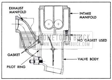
1951 Buick Sectional View of Joints Between Valve Body and Manifolds
- Coat joint surfaces with graphite lubricant, then install intake manifold on exhaust manifold valve body leaving attaching bolts snug but not tight.
- Install intake and exhaust manifold assembly on engine with new intake manifold gaskets.
The individual intake manifold gaskets are centered and the branches of the intake manifold are aligned with the intake ports in cylinder head by pilot rings installed at each joint.
- Exhaust manifold gaskets are not used.
In production, a special compound is used at joints between manifold and cylinder head, and original manifold may be reinstalled without using additional compound. When a new manifold is installed, however, coat the joint surfaces with a thin fluid mixture of graphite and oil.
- Tighten bolts and nuts in the following sequence, using a torque wrench; avoid excessive tightening.
- Tighten manifold to cylinder head stud nuts to 25-30 ft. lbs. torque.
- Tighten exhaust manifold to valve body stud nuts to 25-30 ft. lbs. torque.
- Tighten intake manifold to valve body bolts to 15-20 ft. lbs. torque.
3-13 REPLACEMENT OF 1951 BUICK GASOLINE TANK OR FILLER
When removing 1951 Buick gasoline tank, disconnect feed pipe from gasoline gauge pipe, support the tank while disconnecting support straps at rear ends, then lower tank far enough to disconnect the wire from gasoline gauge.
When installing gasoline tank by reversing procedure for removal, make sure that all road dirt is cleaned from gasoline gauge and wire terminal; also make sure that wire is securely attached to gauge and that insulation is folded over the terminal and snapped over the wire. An accumulation of road dirt around the gauge terminal may permit an electrical leak that will affect the accuracy of the gauge. Insulating strips must be located between the tank and the upper supports on body.
The gasoline tank filler and the vent pipe are furnished separately so that they may be replaced if damaged. After unsoldering the old parts, the new filler and vent pipe should be installed in gasoline tank in accordance with the dimensions given in figure 3-14. Joints must be thoroughly soldered and should be tested for leaks with gasoline before installing gasoline tank.
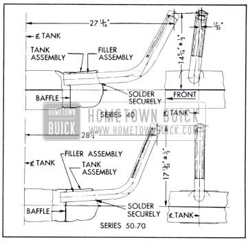
1951 Buick Location Dimensions for Installing Gasoline Tank Filler
Leave A Comment
You must be logged in to post a comment.