6-1 REAR AXLE SPECIFICATIONS AND DESCRIPTION
General Specifications
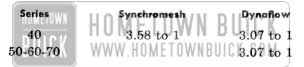
The general specifications remain the same as in 1956 except that the torque specifications for torque tube to torque ball bolts have been changed from 30-35 ft. lbs. to 45-55 ft. lbs. and there is a change in gear ratios. The following gear ratios are standard; optional ratios are not available.
1957 Buick Transmission Specifications
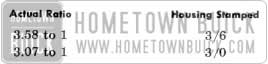
The gear ratio is indicated by numbers stamped on bottom of axle housing as follows :
1957 Buick Gear Ratio
Rear Axle Description
The differential is basically the same as used in late production 1956, with bushings in the supports and 0-rings in the axle bearing outer races. The felt and rubber seal between rear propeller shaft and pinion shaft is also maintained, permitting the use of a lighter type grease in the coupling.
The diameter and length of the side gear hub have been increased thus giving a larger bearing area. Due to this change, several of the differential part specifications have been altered. This will not allow interchangeability of differential parts between 1956 and 1957.
Two differential cases will be used in 1957. A different size case will be used on Dynaflow equipped cars from that used on Synchromesh equipped cars.
Since Buick’s overall car height has been lowered for 1957, the use of a depressed two-piece torque tube has replaced the straight one-piece torque tube used in 1956. See Figure 6-1.
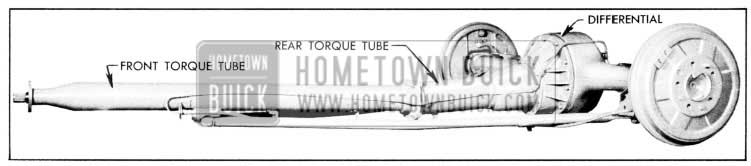
1957 Buick Rear Axle Assembly
Because of this depressed type torque tube, a two-piece propeller shaft is necessary. The front and rear shaft are connected by an additional universal joint that is supported in the torque tube by a bearing. See Figure 6-2.
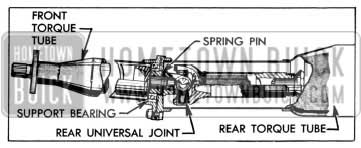
1957 Buick Rear U-Joint
6-2 REMOVAL, INSPECTION AND INSTALLATION OF TORQUE TUBE AND PROPELLER SHAFT ASSEMBLY
Removal of Torque Tube and Propeller Shaft Assembly
- Remove rear axle assembly from car.
- Place axle on suitable stand.
- Remove brake lines from rear axle housing and torque tube.
- Disconnect strut rods from torque tube.
- Remove front to rear torque tube bolts and remove front torque tube and propeller shaft assembly. To disassemble propeller shaft assembly, support the universal joint and drive out spring pin with punch. See Figure 6-2.
- Remove rear torque tube from carrier.
- lnspection and Installation of Torque Tube and Propeller Shaft Assembly
- Check propeller shaft and pinion splines for excessive wear and remove any nicks or burrs. Replace propeller shaft seal sleeve if scored or grooved. Inspect propeller shaft rear packing and retainer and replace if worn or damaged. Inspect rear universal joint trunnions and support bearing for excessive looseness. A worn joint may be repaired, but a worn bearing must be replaced.
- Check torque tube flanges and torque tube mounting surface on carrier. Remove any burrs or nicks.
- Pack rear propeller shaft coupling with #1 or #0 grade wheel bearing grease bringing Ievel to inner end of splines.
- Install rear torque tube on carrier with brake return spring bracket down. (No gasket is used.) Torque bolts to 50-60 ft. lbs. Rotate axle housing so rear torque tube extends in a horizontal direction.
- Slide complete propeller shaft assembly into front torque tube until support bearing is seated against shoulder.
NOTE: If propeller shaft has been disassembled be certain to reinstall spring pin.
- Push front torque tube and propeller shaft assembly into place in rear torque tube. If difficulty is encountered in engaging pinion splines, use Socket J-6192 to rotate propeller shaft.
- Position torque tube with strut rod bracket down. No gasket is used between front and rear torque tubes, but make certain that bearing retainer plate is in place. Install front to rear torque tube bolts and nuts. Torque to 65-75 ft. lbs.
- Connect strut rods and torque bolts to 85-100 ft. lbs.
- Install brake lines on rear axle housing and torque tube.
- Install rear axle assembly in car.
6-3 REMOVAL AND INSTALLATION OF PROPELLER SHAFT BEARING
The propeller shaft bearing is a permanently lubricated, sealed ball bearing. The bearing should not be removed except to replace it with a new one when worn or excessively loose.
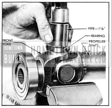
- With rear propeller shaft separated from front propeller shaft, place rear propeller shaft and bearing assembly in a press so that it is supported under the bearing with shaft down.
- Using a sleeve or shaft slightly smaller than inside diameter of bearing, press universal joint front yoke down through bearing.
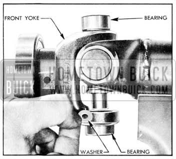
- To install a new bearing, place rear propeller shaft in a press so that it is supported under both sides of front yoke.
- Start new bearing squarely on yoke. Using a heavy flat plate, press bearing on yoke until it bottoms against shoulder.
NOTE: Be careful that bearing does not lock as it starts onto yoke.
6-4 DISASSEMBL Y AND ASSEMBLY OF REAR UNIVERSAL JOINT
Because the rear universal joint is completely protected from road dirt and splash by the torque tube, and the lubricant is held in each bearing by a packing, no additional lubrication is necessary during the life of the universal joint.
A noisy or excessively worn rear universal joint may be repaired.
Disassembly of Rear Universal Joint
- Remove snap rings from bearings using a punch.
- Lay rear propeller shaft assembly on vise so that yoke welded to shaft bears against open jaws of vise. Shaft should be horizontal and front yoke must be free to move vertically between jaws of vise. See Figure 6-3.
1957 Buick Displacing U-Joint Bearing
1957 Buick Installing Washers in Bearing
1957 Buick Removal of U-Joint Bearing
Make sure each bearing assembly has a full b. Assembly of Rear Universal Joint set of needle rollers (25), a cork packing and retainer washer, and is well lubricated with high melting point lubricant.
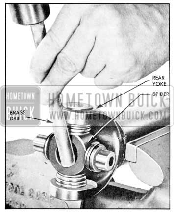
- Drive a bearing in one side of yoke welded to shaft, only as far as snap ring groove, using a soft faced hammer.
- Position spider in partially installed bearing. See Figure 6-6.
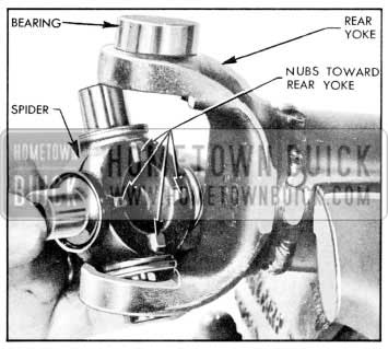
1957 Buick Installation of Spider
NOTE: Spider must be installed so locating Zugs are facing toward propeller shaft tube.
- Hold spider in place to prevent loss of needle rollers and completely install bearing.
- Install opposite bearing making sure that spider is centered so that needle rollers will not be jammed or dislodged. Check movement of spider in bearings for smoothness.
- Start a bearing in one side of front yoke.
- Position yoke and bearing over spider and completely install bearing.
- Install remaining bearing while spider is centered so that needle rollers are not jammed or dislodged. Check for smooth movement of forward yoke.
- Install snap rings.
NOTE: lf snap ring cannot be installed on one side, drive bearing toward other side until snap ring groove is clear of yoke.
Leave A Comment
You must be logged in to post a comment.