SECTION 8-A MANUAL STEERING GEAR
8-1 GENERAL DESCRIPTION
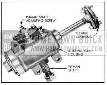
The operation and construction of the 1957 manual steering gear is essentially the same as in 1956 with the exception that the pitman shaft is shorter, and the flexible coupling used on the 1956 power steering gear is also used on the manual steering gear. See Figure 8-1.
1957 Buick Manual Steering Gear
The use of the flexible coupling allows the use of the same upper steering shaft and column jacket on both manual and power steering gears. The coupling also makes it possible to remove the manual gear through the bottom of the engine compartment without removing the upper steering shaft and column jacket. Both types of steering gears are mounted to the frame with three (3) bolts.
NOTE: Mark upper and lower steering shaft flanges for correct assembly before disconnecting.
An Allen adjusting screw is used for ease in adjusting the pitman shaft for both manual and power steering gears.
The ratio of the 1957 manual steering gear is 23.6 to 1 as compared to 25.8 to 1 used in 1956. The decrease in gear ratio is compensated for by a greater linkage ratio and by the reduced steering effort resulting from the use of ball thrust bearings on the worm shaft, replacing the spherangular bearings used in the previous gear. These new ball bearings increase the efficiency of the gear, and maintain their preload Ionger due to more uniform bearing surfaces which equalize wear. They transmit the same thrust with lower preload adjustment, making it possible to lower the worm adjustment from 7/7 – 1 1/8 to 1/2 – 7/8 lbs., thereby reducing the steering effort. The bronze bushings for the pitman shaft used on the 1956 models have been replaced with needle bearings in both the housing and the side cover. See Figure 8-2.
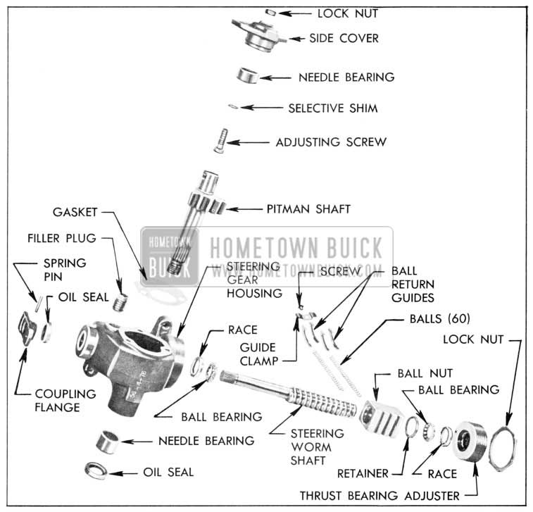
1957 Buick Manual Steering Gear Disassembled
8-2 DISASSEMBLY AND ASSEMBLY OF MANUAL STEERING GEAR
The manual steering gear overhaul procedures are basically unchanged. If the pitman shaft needle bearings require replacement, the upper bearing (in the side cover) is removed by using Reaction Shaft Flange Bushing Re mover, J-5822, with Slide Hammer, J-1436. The lower bearing can be removed by using pitman Shaft Bearing Installer, J-6619, which is also used for installing the new bearings. See Figure 8-3.
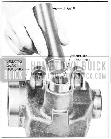
1957 Buick Installing Needle Bearing in Steering Gear Housing
The Over-Center Adjuster, J-6281, should be used when checking the steering gear adjustment following overhaul. Worm bearing preload is 1/2 – 7/8 lbs. and pitman shaft adjustment (high-point) is 1 1/2 – 2 lbs.
8-3 STEERING LINKAGES
The steering linkages, manual and power steering, in 1957 are basically the same as the ones used in 1956, except that a heavier idler arm and support will be used, as well as heavy duty tie-rod clamps to withstand increased Ioads on these parts resulting from the new design of the front suspension.
8-4 DESCRIPTION OF POWER STEERING GEAR
In line with the new lower body, the pitman shaft has been shortened and the entire gear lowered in the frame side rail.
The pressure and return hoses enter the valve body at the lower end rather than on the top. See Figure 8-4.
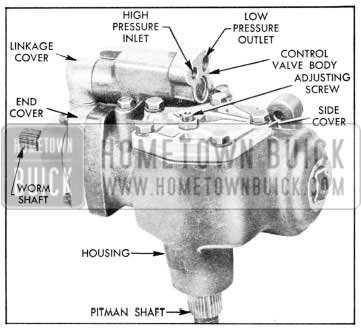
1957 Buick Power Steering Gear
To reduce the possibility of leaks at the pitman shaft seal, an additional single lip seal is installed ahead of the double lip seal.
Both seals have a steel washer behind them. No leather dust seal is used in 1957. See Figure 8-5.
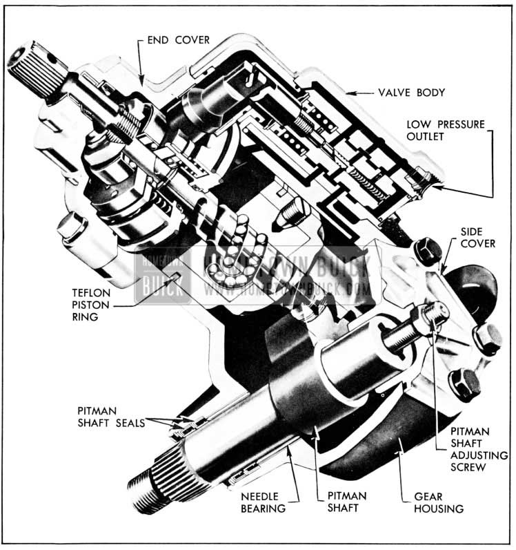
1957 Buick Phantom View of Power Steering Gear
The adapter and end cover are redesigned to reduce the possibility of leaks. The O-ring at the outer diameter of the adapter is moved to the front of the adapter. To provide a better bearing surface in the side cover, the T-slot in the pitman shaft is eliminated. The adjusting screw is held in place by a plug threaded into the pitman shaft over the head of the adjusting screw. The end play of the adjusting screw is limited to .002″ and is controlled by the plug. To adjust the end play of the adjusting screw, tighten plug down and back off so that the adjusting screw is just free to turn, then stake the plug in place. There is no nylon pin in the adjusting screw and the sealing is provided by a Teflon ring in the adjusting screw lock nut.
A one piece Teflon piston ring is used to reduce ring drag and improve sealing.
A needle bearing supports the pitman shaft in the housing, instead of the bushings that were previously used.
A finer pitch thread is used on the worm for the thrust bearing adjusting nut, to provide a more accurate adjustment.
8-5 DISASSEMBLY AND ASSEMBLY OF THE POWER STEERING GEAR
The disassembly and reassembly procedure remains about the same as for the 1956 unit.
To install rack piston, use Piston Ring Compressor, J-6216, to prevent cutting the Teflon seal.
Remove the pitman shaft seals as outlined in B.P.S. Bulletin 2.403 using hydraulic pressure. To install seals, install the single lip seal over taped pitman shaft with lip of seal in, and start it into bore; then install steel washer, the double lip seal and the second steel washer. Drive both seals in place using Installer, J-6219.
To remove or install needle bearing, use Remover and Installer, J-6657. Do not remove needle bearing unless it requires replacement as it cannot be removed without damage.
8-6 POWER STEERING GEAR LINKAGE
The pitman arm for the power steering gear has a larger spline to fit the larger pitman shaft, and both the pitman arm and idler arm for power steering are no longer than for the manual steering gear. By the use of the longer pitman arm and idler arm, with the same steering arms, faster response is possible for the power steering gear, while the use of the shorter pitman arm in the manual gear allows for reduced steering effort.
8-7 POWER STEERING PUMP
The 1957 Saginaw power steering gear pump is similar in design to the pump used in 1956 with the exception of the following items.
The return line hose has been moved from the side of the reservoir to the rear to accommodate the new battery location. A bronze bushing has replaced the inner needle bearing. See Figure 8-6.
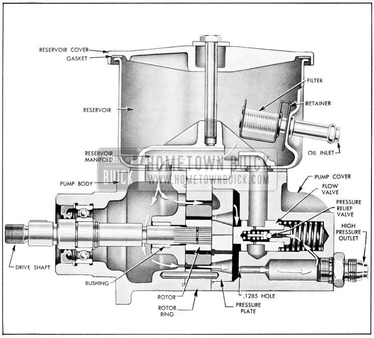
1957 Buick Power Steering Pump, Sectional View
The outer ball bearing, which is now an open bearing, has been moved inside the drive shaft seal and is lubricated by the oil inside the pump.
The shaft diameter is reduced from .749″ to .624″ at the pulley location.
The cross section of the two “0” rings on each side of the pump ring has been increased from 1/16″ to 3/32″ in diameter to improve sealing.
8-8 DISASSEMBLY, INSPECTION, ASSEMBLY OF SAGINAW OIL PUMP
The disassembly, inspection and assembly of the oil pump remains about the same except for the following:
The oil seal is removed by driving a screw driver through the seal close to the outer diameter and prying the seal out as shown in Figure 8-7.
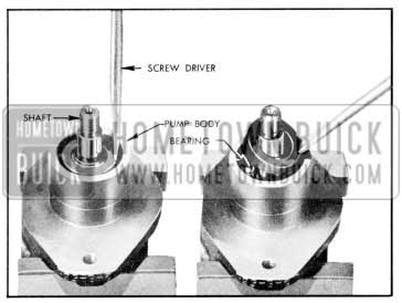
1957 Buick Removal of Oil Seal
Remove bearing retainer ring with Truarc Pliers, J-4245, and remove bearing and shaft. Seal is installed by using Seal Installer, J-6539. See Figure 8-8.
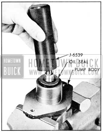
1957 Buick Installation of Oil Seal
NOTE: The bushing replacing the needle bearing used in 1956 is not replaceable.
Hello folks. I need to know what model manual steering gear goes in the 1957 Special. Its a Saginaw, number on the case is 5670373. I’m seeking a replacement or a rebuild kit.