GENERAL ENGINE SPECIFICATIONS
1957 Buick General Specifications
2-1 ENGINE DESCRIPTION
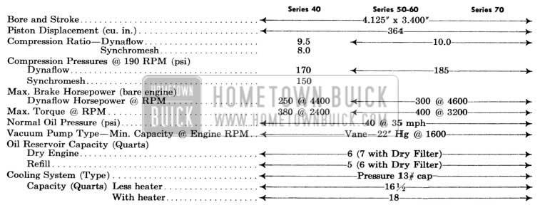
The Buick engine has been increased in size for all 1957 models. All series use the same basic engine with a bore of 4.125″, and a stroke of 3.4″, and a piston displacement of 364 cubic inches. The larger displacement is partly due to the crankshaft stroke, which has been in creased .2″, and the bore which has been increased .125″. The connecting rods are .1″ longer, and the crankshaft has thicker counter weights for greater strength and durability.
In line with the increase in bore and stroke are increases in valve diameter, lift, and throat area. Changes in valve timing and exhaust manifolding also improve engine breathing. Carburetors in all series have been changed to match the greater engine displacement. By removing the rotor resistor and the spark plug covers, and using a new resistance-type cable, increased voltage has been obtained at the spark plugs.
The 50-60-70 engines have a compression ratio of 10.0 to 1 while Series 40 engines have a ratio of 8.0 to 1 on synchromesh cars, and 9.5 to 1 on cars equipped with Dynaflow. The difference in compression ratios is accomplished by different piston dome heights. The 50-60-70 Series use the four-barrel carburetor while the two-barrel carburetor is used on Series 40. A .015″ steel head gasket is used on all series.
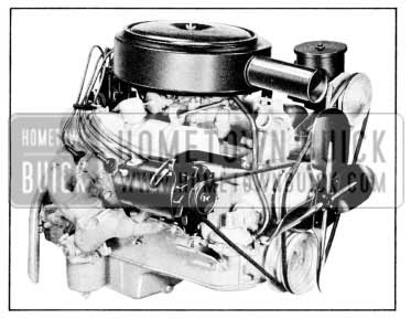
The vacuum pump has been relocated in the oil pan, permitting the location of the fuel pump in a lower, cooler position, reducing the tendency of vapor lock. See Figure 2-1.
1957 Buick 1957 Engine
Beginning with 1957 production, a new engine numbering system will be used. The vehicle identification number (serial number) will be stamped to the left on an extension of the engine block just forward of the valve lifter cover, in addition to the tag on the left front door pillar. This number alone will constitute a legal identification for both body and engine on titles, registrations, etc.
The manufacturing number ( engine identification number ) is stamped on the same surface as the vehicle identification number, but to the right and inverted (must be read from the rearward side). This number will be used only for engine identification (along with the vehicle identification number) on product reports, etc., and does not constitute a legal identification for the engine. This manufacturing number will begin with the number 1 and each engine will be numbered consecutively through out the model year. As before, a 1,4,” long dash following this number indicates a .010″ over size engine.
2-2 ENGINE CONSTRUCTION
Cylinder Crankcase
The cylinder block height has been increased by .250″ due to the additional .1″ in the length of the connecting rod, and the added .1″ in the crankshaft throw, and .050” in the pistons.
To obtain a more positive clearance between the counterweight faces and crankcase, the main bearing supports and caps are now machined.
The size of the rear water passage has been increased to give greater flow and better cooling. The increased displacement and horse power has been accomplished without any appreciable increase in the weight of the engine.
Crankshaft and Bearings
To permit additional thickness of the counterweight, the crankpins and main bearing journals are reduced in length. This thicker counterweight provides better balance to compensate for the increased throw and the heavier component parts such as pistons, pins and rods. An improved main bearing material is used to compensate for the reduction in area.
The harmonic balancer has been redesigned to obtain greater strength and durability. The pilot diameter has been reduced .060″ to in crease the hub section .030″, resulting in greater strength at the keyway section.
The engines used with the Dynaflow transmission have a triangular steel flywheel for torque converter coupling. See Figure 2-2.
1957 Buick Triangular Flywheel
The synchromesh engine (Series 40) is equipped with a cast iron flywheel for clutch application and the crankshaft flywheel flange contains a clutch pilot bushing.
Connecting Rods, Pistons and Pins
The pistons have been increased in diameter from 4.000″ to 4.125″, and the dome heights have been increased for higher compression ratios.
There are three types of pistons for 1957 which may be identified as follows: The pistons used in the Series 40 synchromesh engine are marked with the letter “X” on the dome, and the Series 40 Dynaflow engine pistons are marked with the letter “L”. The pistons used in 50-60-70 Series engine have no identifying marks.
The length and diameter of the piston pin have been increased .100″ and .055″ respectively for additional strength and bearing area..
The new connecting rods and rod caps can be identified by two conical bosses on the web of the rod and two ribs on the caps. See Figure 2-3.
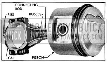
1957 Buick Piston and Connecting Rod
Cylinder Heads
The cylinder heads have been modified in that the throat area of both intake and exhaust ports has been increased. The exhaust port has been redesigned to improve the flow of exhaust gases by maintaining a more uniform cross sectional shape, both in the exhaust port and continuing into the exhaust manifold. The in take port has been enlarged at the junction with the intake manifold.
Camshaft and Valve Mechanism
The cam contour has been changed to improve breathing and increase power. The exhaust and inlet cam-lift have been increased from .2519″ to .2819″, resulting in a valve-lift increase from .378″ to .423″. The exhaust opening has been reduced 5 degrees and the inlet opening has been increased the same amount. Over-all head diameter of the intake valve has been increased from 1.750″ to 1.875″, and the exhaust valve diameter from 1.375″ to 1.438″. Valve spring tension has been increased to in sure more positive closing of the valves at higher speeds. The same camshaft is used on all series except the Series 40 synchromesh. All Dynaflow camshafts may be identified by two grooves just forward of the No. 3 bearing journal. The synchromesh camshafts have no identifying marks. The camshaft thrust plate has been eliminated since the thrust loads are al ways toward the rear of the engine.
Timing Chain and Sprockets
The timing chain and sprockets for 1957 have been changed as follows: The copper plated washers on the timing chain have been omitted and the “0” timing marks on the sprockets have been relocated as shown in Figure 2-4.
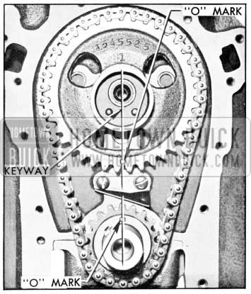
1957 Buick Timing Chain and Sprockets
When installing the timing chain and sprockets the “0” timing marks are aligned adjacent to each other along the centerline of the camshaft and crankshaft sprockets.
Cooling System
A 13 lb. pressure cap is used on all series including air conditioned cars.
2-3 OIL AND VACUUM PUMP
Oil Pump
The oil pump for 1957 has been redesigned and reduced in over-all height to allow room for installation of a vacuum pump to the bottom of the oil pump. The oil intake screen is located in the bottom of the vacuum pump housing, and the oil is fed to the oil pump through the vacuum pump housing. The height of the oil pump gears has been reduced and the number of teeth changed from 14 to 8, thus obtaining a net capacity increase of nearly one gallon per minute through most of the speed range. A ball type relief valve is used instead of the piston type, resulting in less tendency toward sticking. See Figure 2-5.
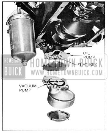
1957 Buick Oil and Vacuum Pump
Vacuum Pump
The vacuum pump is a vane type pump consisting of a powdered metal rotor with two spring-loaded fiber (Spauldite) vanes enclosed in a zinc die-cast housing. This assembly rests against the steel plate located on the bottom of the oil pump and the vacuum pump rotor is driven from the oil pump idler gear by a flat key that extends through a hole in the common cover plate. The vacuum passage extends through the crankcase and oil pump housing to the vacuum pump and the air is exhausted into the oil pan. This vacuum passage emerges from the crankcase just to the rear of the oil filter. This new pump has an increased static vacuum and air pumping capacity compared to the diaphragm type previously used. The capacity increase was required for the windshield wiper motor due to the larger windshield and Ionger wiper blades that are used in 1957.
Leave A Comment
You must be logged in to post a comment.