SECTION 9-A MANUAL BRAKES
9-1 GENERAL INFORMATION
Location
Both manual and power brake pedals are suspended from a new bracket located under the instrument panel. The master cylinder location has been moved from the toe-board and placed at the left ventilation air duct cover assembly. The residual check valve is built into both manual and power brake units, eliminating a separate check valve Iocated at the junction block as on 1956 cars. See Figure 9-1.
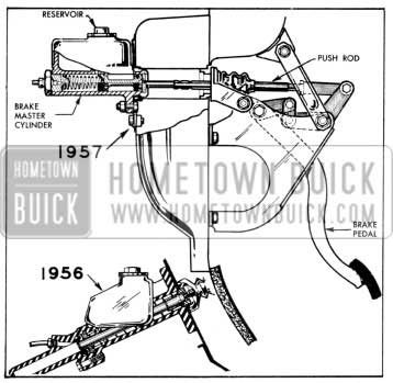
1957 Buick Manual Brake Installation
Construction
With the exception of an embossment on the cylinder body for the stop light switch and the mounting adapter and tube assembly used to mount the cylinder to the ventilation duct, the 1957 manual unit is basically the same as that which was used in 1955 production and disassembly and assembly remain the same. It has a pedal ratio of 6.0 to 1 with a 6.74 inch travel for the brake pedal.
9-2 BRAKE PEDAL HEIGHT ADJUSTMENT
Correct brake pedal height is important to insure adequate pedal travel and to make sure that the pedal is in the proper position to get the best linkage action.
- Make certain that brake pedal returns completely when released slowly. If pedal does not return freely, check linkage for binding and check condition of pedal return spring.
- Measure from side of pedal pad perpendicular to toe pan using a foot ruler. Pedal height with ruler pressed firmly against floor mat should be between 7 1/2 and 8 inches on Dynaflow cars. On synchromesh cars, brake pedal height should be within 1/4 inch of clutch pedal height.
- If pedal height is incorrect, loosen push rod lock nut.
- Turn push rod as necessary to adjust pedal height to 7 3/4 inches on Dynaflow cars or same as clutch pedal height on Synchromesh cars.
- Hold push rod and tighten lock nut. Recheck pedal height.
- Depress brake pedal firmly. If pedal travels to within 2 inches of toe pan and has a hard feel, brake shoes require adjustment or relining. However, if pedal has a spongy feel, brake system requires bleeding.
9-3 REMOVAL AND INSTALLATION OF BRAKE MASTER CYLINDER
- Removal of Brake Master Cylinder
- Disconnect battery ground strap.
- Remove clevis pin from push rod clevis.
- Lift brake pedal to pull linkage out of the way, then remove large nut holding master cylinder to cowl, using Wrench J-6618.
- Disconnect stop light wire connector from switch.
- Disconnect brake pipe from master cylinder and tape end of pipe to prevent entrance of dirt.
- Remove bolts holding master cylinder to ventilation air duct and remove cylinder from car.
- Clean outside of master cylinder thoroughly. Remove filler cap, turn cylinder over, and pump push rod by hand to drain all brake fluid. Always discard used fluid.
- Installation of Brake Master Cylinder
- Install master cylinder assembly on ventilation air duct.
- Connect brake pipe to master cylinder.
- Connect stop light wire connector to switch.
- Loosen brake reinforcing bracket holt and nut. Lift brake pedal to pull linkage out of the way, then install and tighten large nut, using Wrench J-,6618. After large nut is tight, tighten reinforcing bracket holt and nut.
- Install spring washer, clevis pin, and cotter key in push rod clevis.
- Check brake pedal for correct height as described in paragraph 9-2. Adjust pedal height if necessary.
- Reconnect battery ground strap.
- Bleed hydraulic system. After bleeding bring fluid Ievel to % inch below lip of filler opening.
- Road test car for proper brake performance.
SECTION 9-B POWER BRAKES
9-4 POWER BRAKE UNITS
Description
There are two different types of power brake units used in 1957 production. One type is the Bendix Treadle-Vac and the other is the Moraine Power Brake Unit. General changes applicable to both units are as follows:
- The detachable fluid reservoir has been deleted, the reservoir being part of the hydraulic cylinder housing.
- As an integral part of the piston, both the Moraine and the Bendix Power Brake units contain a relief valve that allows instantaneous braking applications when engine is stalled and vacuum reservoir is exhausted. See Figure 9-2.
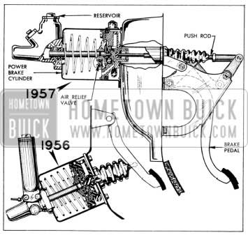
1957 Buick Power Brake Installation
To remove and install the power brake cylinder follow the same procedure for removal and installation of master cylinder as outlined in Paragraph 9-3 with one additional step: Removal and installation of the vacuum lines.
9-5 BENDIX POWER BRAKE UNIT
Construction of Bendix Power Brake Unit
The Bendix power brake unit consists of two basic sections combined into a single unit; these are the vacuum power cylinder and the hydraulic master cylinder. The vacuum power cylinder consists of a cylinder, a power piston and valve assembly, a piston return spring, a valve operating rod and a hydraulic plunger assembly. The hydraulic master cylinder consists of a hydraulic cylinder, a reservoir, a residual check valve, a compensating valve, and the forward end of the hydraulic plunger with its cup and seal. See Figure 9-3.
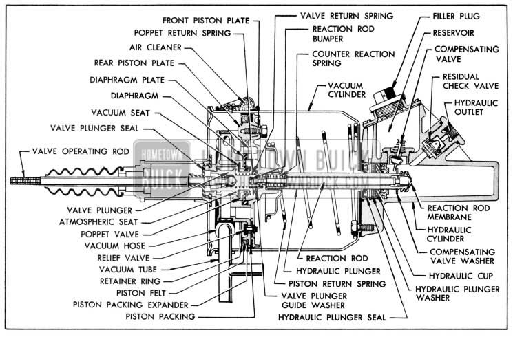
1957 Buick Bendix Power Brake
The power piston and the components which make up the valve assembly are connected to the brake pedal through the valve operating rod. The valve operating rod is connected to the valve plunger which operates within the power piston. The valve return spring is incorporated to return the valve plunger and the valve Operating rod to the released position when the brakes are released. A separate pop pet type air relief valve is built into the power piston; this valve functions only when a brake application is made without vacuum assist.
The valve portion of the power piston consists of a poppet valve, an atmospheric port and a vacuum port. The atmospheric port seat is Iocated on the valve plunger while the vacuum port seat is located in the rear half of the power piston.
The poppet valve is assembled into a flexible diaphragm in the power piston. A diaphragm plate is used in conjunction with the diaphragm to Iimit the effective area of the diaphragm. When the power cylinder is in the released position, the poppet return spring overcomes the force present on the poppet as a result of the atmospheric pressure on the left side of the poppet and the vacuum on the right side of the poppet so that the return spring holds the poppet on the vacuum seat. A valve plunger seal is used to seal the opening between the rear piston plate and the valve operating rod.
The power piston is in contact with the hydraulic plunger at all times and thereby transmits the force of the piston to the fluid in the hydraulic cylinder. A reaction rod which is a part of the hydraulic plunger assembly operates within the hydraulic plunger to transmit a “reaction force” back through the rod against the valve plunger. A counter reaction spring located between the power piston and reaction rod, permits initial application of power before sufficient hydraulic pressure is developed with in the hydraulic cylinder to react through the reaction rod membrane at the end of the hydraulic plunger and the reaction rod.
The hydraulic cylinder with the fluid reservoir is attached to the end of the vacuum cylinder. The hydraulic cylinder is sealed off from the vacuum cylinder at the hydraulic plunger by a leather wiper seal and a rubber cup. A compensation valve is placed between the hydraulic cylinder and the fluid reservoir. This valve is of the tilting type and is closed at all times except when the hydraulic plunger is in its fully released position. A residual check valve which is located at the output end of the hydraulic cylinder traps a slight pres sure in the hydraulic lines and wheel cylinders when the brakes are released as in the conventional brake system. This prevents the entrance of air into the hydraulic brake lines upon release of the brakes.
Operation of Bendix Power Brake Unit
Description of power brake operation will cover (1) Released Position, (2) Applying, (3) Reaction Pressure, (4) Holding, (5) Releasing, ( 6) Manual Applying.
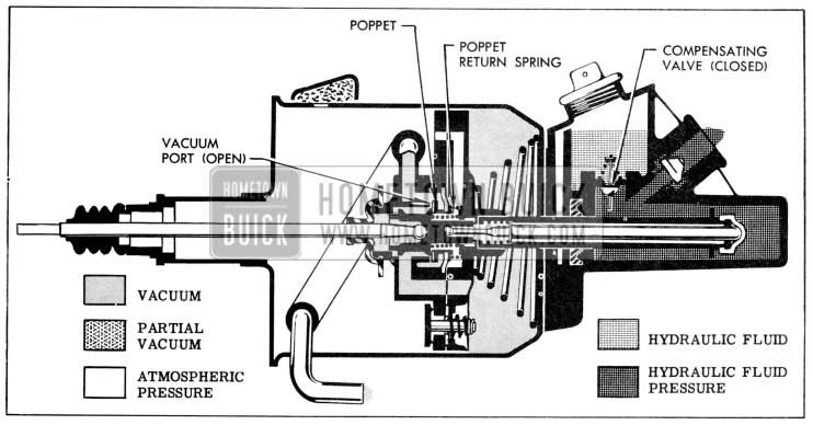
- Released Position. See Figure 9-4.
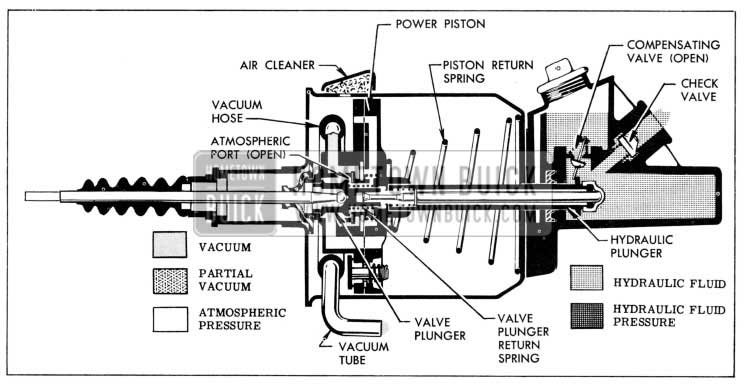
1957 Buick Released Position
When the engine is running and the brakes are re leased, vacuum from the engine intake manifold is transmitted through the vacuum check valve to the power brake vacuum tube and to the vacuum reservoir. Vacuum is transmitted into the power brake unit through an internal vacuum hose which is attached to the power piston at the rear side. Atmosphere is always present on the left side of the power piston through the air cleaner. In the released position, as shown in Figure 9-4, the driver’s foot pressure is removed from the valve operating rod. This allows the valve operating rod and valve plunger to be held to the rear in the power piston by the valve return spring, thus opening the atmospheric port and closing the vacuum port. With atmosphere present on both sides of the power piston, the piston return spring (attached to the hydraulic plunger) holds the hydraulic plunger and power piston assembly in the released position.When the power piston and valve operating rod are in their released positions, the various parts of the hydraulic master cylinder are also in their released positions. The compensating valve is tilted by the washer at the end of the hydraulic plunger permitting fluid flow from the reservoir to the hydraulic cylinder. The expansion, contraction or leakage of fluid is thereby compensated for as in a conventional brake system. The residual pressure check valve maintains fluid under slight pressure in the lines and wheel cylinders to prevent the entrance of air into the hydraulic system.
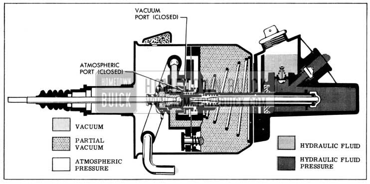
1957 Buick Applied Position
As the brake pedal is depressed, the valve operating rod moves the valve plunger and closes the atmospheric port. After the atmospheric port is close against the poppet, further movement of the valve operating rod and plunger moves the poppet valve, compressing the poppet return spring and opening the vacuum port. With the vacuum port open, vacuum is admitted through the piston passages to the forward side of the power piston. With partial vacuum on the for ward side of the power piston and atmosphere on the rear side of the piston, the differential in pressure creates a force which moves the power piston forward, moving the hydraulic plunger with it. Initial movement of t he plunger allows the compensating valve to seat and trap fluid in the hydraulic cylinder. Fluid under pressure is then forced through the residual pressure check valve and brake lines to the wheel cylinder.
1957 Buick Holding Position
When the force applied by the driver remains constant, the valve is allowed to remain in its holding position. In the holding position both the vacuum and the atmospheric ports of the poppet valve are closed. However, any increase in the force applied by the driver to the valve operating rod and plunger will cause the vacuum port to reopen, admitting more vacuum to the for ward side of the power piston. This will cause the power piston to move farther forward until it again “catches-up” with the valve plunger and poppet. The vacuum port will then close and the valve is again in the holding position.
9-6 DISASSEMBLY, INSPECTION, ASSEMBLY OF BENDIX POWER BRAKE UNIT
NOTE: Refer to Figure 9-3 for identification of parts not shown in figures next to overhaul steps.
Disassembly of Power Unit
- Measure distance push rod projects through clevis. Record this dimension so that clevis can be reinstalled in same position. Then remove clevis.
- Clamp unit in vise and remove rubber dust boot from tube on end plate and from push rod. Bend out tabs on ei1d plate. Remove end plate and gasket.
- Slide vacuum hose off vacuum tube. Remove vacuum tube attaching screws, vacuum tube and gasket.
- Remove air cleaner attaching screw and screw gasket. Remove air cleaner shell, hair and rubber gasket.
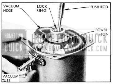
- Remove burrs from inside of vacuum cylinder at air cleaner and vacuum tube attaching screw holes. Then pull out power piston and valve assembly from cylinder. See Figure 9-7.
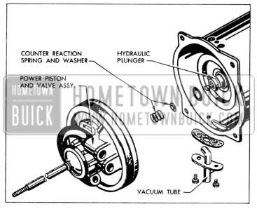
1957 Buick Removing Power Piston Assembly
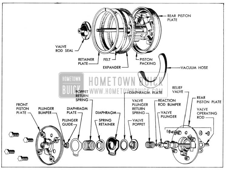
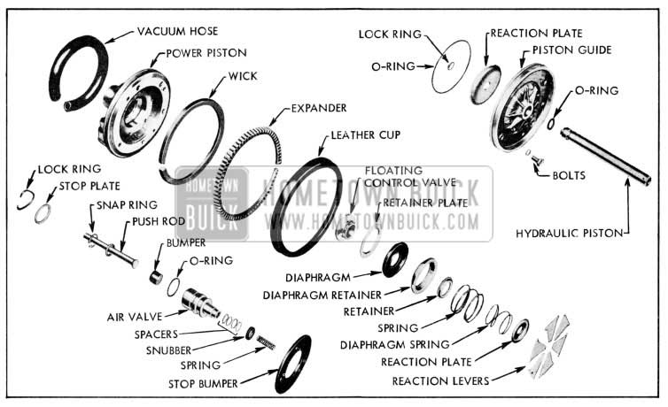
1957 Buick Vacuum Power Piston Assembly Exploded
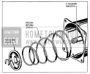
1957 Buick Removing Piston Return Spring
1957 Buick Removing Vacuum Cylinder from Hydraulic Cylinder
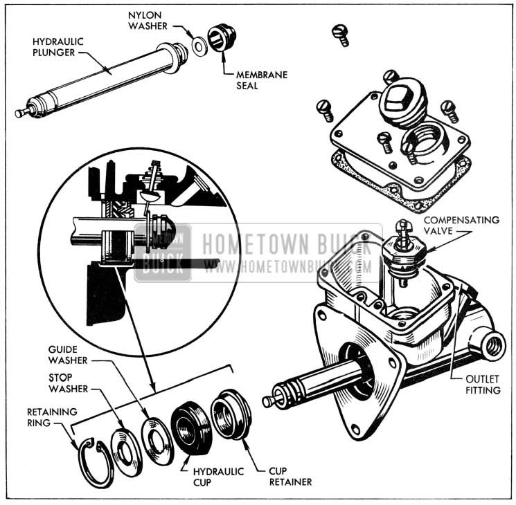
1957 Buick Hydraulic Cylinder Assembly Exploded
1957 Buick Disassembling Compensating Valve
Cleaning, lnspection, Replacement of Parts
The cleaning and inspection procedure in general is the same for the Bendix as it is for the Moraine power brake unit.
Assembly of Bendix Power Brake Unit
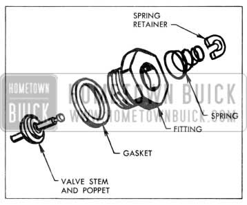
- To assemble compensating valve, clamp fitting in vise, then insert valve stem and poppet through hole in fitting from threaded end. Assemble large diameter end of spring over stem, hold valve poppet on seat, compress spring and assemble new spring retainer washer in groove of valve stem. See Figure 9-12. Squeeze ends of washer together with pliers. Assemble new gasket over threads of fitting. Do not install compensating valve assembly in hydraulic cylinder at this time.
- To assemble residual check valve, assemble new gasket over threads of hydraulic outlet fitting. Hold outlet fitting in vertical position and insert cone end of check valve cup and retainer in fitting. Place check valve spring in recess of retainer. Hold hydraulic master cylinder so that outlet hole is straight down and thread outlet fitting and check valve assembly into hydraulic cylinder hand tight. See Figure 9-11.
- Clamp hydraulic cylinder in vise. Assemble nylon washer and rubber membrane on end of hydraulic plunger. Insert membrane end of plunger in cylinder. Then install cup retainer (smaller hole against fixed washer), rubber hydraulic cup (lip side in first), fiber plunger guide washer and steel stop washer. Slide plunger and hydraulic cup parts in as far as possible, then install hydraulic cup retainer ring in ring groove. See Figure 9-13.
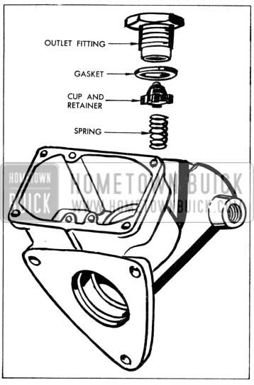
1957 Buick Removing Residual Check Valve
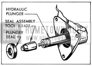
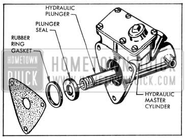
1957 Buick Installing Plunger Seal
Press seal into recess of hydraulic cylinder and then remove toot.
9-7 DISASSEMBLY, INSPECTION, ASSEMBLY OF MORAINE POWER BRAKE UNIT
Disassembly of Power Unit
NOTE: Refer to Figure 9-15 for identification of parts not shown in figures next to over haul steps.
1957 Buick Moraine Power Broke Parts
- Mount power brake unit in vise with hydraulic cylinder down, being careful not to damage the loose vent pin in flange of hydraulic cylinder. Tighten vise only enough to hold cylinder firmly; excessive tightening will distort or crack cylinder.
- Remove push rod boot from housing cover tube and from push rod. Remove feit air silencer from push rod.
- Take out air cleaner screw and remove air cleaner cover and filter.
- Take out vacuum tube screws. Remove housing and cover screws, cover and gasket. While holding power piston down, disconnect vacuum hose from vacuum tube and remove tube and gasket from housing. See Figure 9-16.
1957 Buick Removing Vacuum Tube
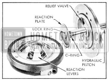
1957 Buick Reaction Plate and Related Parts
1957 Buick Removing Cylinder Plug
CAUTION: Do not use anti-freeze alcohol, gasoline, kerosene, or any other cleaning fluid that might contain even a trace of mineral oil, as this could cause serious damage to all rubber parts in the brake system.
- Carefully examine the cleaned parts for nicks, burrs, stripped threads, damage or excessive wear. Replace damaged or excessively worn parts or housings. If inside of vacuum power cylinder is rusted or corroded, polish with steel wool or fine emery cloth. Replace when scored.
- Make certain that the small compensating ports in end of hydraulic piston are clear. If these ports are plugged, clean them thoroughly and flush the hydraulic system to remove all dirt.
- If the outer surface of the air valve or the hydraulic piston show evidence of abrasion, polish out light scores with crocus cloth or very fine polishing paper, then wash and dry thoroughly.
- If any parts indicate that heavy abrasive action has resulted from severe contamination of the brake fluid, replace damaged parts and be sure to thoroughly flush the reservoir and valve cylinder lines.
- Make sure that the loose pin is properly retained in vent hole in flange of hydraulic cylinder body, and that vent hole is clear.
- The Power Brake Cylinder Overhaul Kit ( Group 4.898) contains all necessary replacement parts for the power brake cylinder. When assembling the brake cylinder use all the new parts in the kit regardless of whether the old parts appear fit for use. Discard all old rubber parts. In addition, replace any other parts which inspection indicates to be unfit for use.
- Lubricate all hydraulic master cylinder parts which require lubrication with clean brake fluid. Lubricate vacuum power piston parts where lubrication is specified with Dynaflow oil. Do not lubricate parts until just before installation.
- Assembly of Moraine Power Brake Unit
- Clamp hydraulic master cylinder body in vise with threaded outlet hole straight up. Into this hole, place check valve spring and lower new check valve concave side out to seat on spring. Place new gasket and stretch new seat washer onto head nut. Set head nut squarely against check valve and press against spring to hold check valve in position while head nut is started in threads. Run down finger tight, back off one or two turns to allow check valve to center, then torque to 85-90 ft. lbs.
- Reposition hydraulic cylinder in vise with large bore straight up. Wipe bore and threads with a thin coat of clean brake fluid.
- Into bore, set conical primary cup retainer with notched end in first. Dip primary cup in clean brake fluid and install lip side first over retainer. Center lip of cup must fit in hole. Set primary cup ring of thin blued steel on flat of primary cup. With notched face out, place piston bearing on primary cup ring with hub of bearing fitting into opening in cup, then press home to solid seat. Now set dark secondary cup retainer to center on bearing and position ex pander on retainer with notched side in.
- On master cylinder plug, install two 0- rings on first and third grooves of plug. Do not place an 0-Ting in center gloove which has four small vent holes. Install vacuum seal in bottom of bore in plug flat side down. Position light colored retainer on seal, then install flat sup port on shoulder in bore. Place secondary cup flat side down against support.
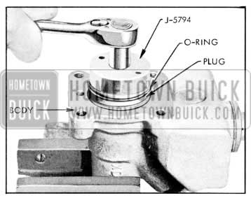
- Moisten 0-rings on plug with clean brake fluid and screw plug assembly into hydraulic body, checking that secondary cup retainer and expander are centered. Use Wrench J-5794 to tighten plug to 20-30 ft. lbs.
- If vent pin was removed, install in vent hole and bend to about 45° angle to hold in place. Set assembled hydraulic cylinder aside to protect from dirt or damage.
- To assemble floating valve assembly, stretch new diaphragm to fit in groove on diaphragm retainer. See Figure 9-19.
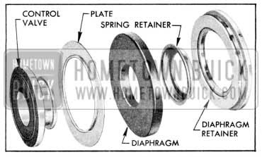
1957 Buick Control Valve and Diaphragm Disassembled
Hold flat side of retainer plate against flat side of diaphragm while pressing floating control valve into center hole of diaphragm. Use thumbs to stretch diaphragm over hub of floating control valve, then press spring retainer over valve hub and diaphragm lip. Lubricate O.D. of floating valve and press into place in power piston with rubber face of floating control valve facing in.
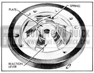
1957 Buick Assembly of Reaction Levers
NOTE : To assure that reaction levers are properly seated, check to see that master cylinder piston has a slight movement in power piston assembly.
- Coat one side of sponge rubber piston stop bumper with weatherstrip adhesive and air dry for 30-60 seconds. Install bumper in groove on hub of power piston.
- If push rod was disconnected from air valve, install bumper, push rod and washer. Then install snap ring using No.1 Truarc Pliers J-5403. Check for proper seating of snap ring with a hard pull on push rod.
- Set spacers (as removed) on Gauge J-5805. Hold power piston assembly with air valve bore down and insert gauge and spacers. (The body of the gauge sets against the smaller reaction plate while the pin of the gauge ex tends through to contact the master cylinder piston.) Now turn whole assembly over to bring gauge on top and observe gauge pin in gauge body as shown in Figure 9-21.
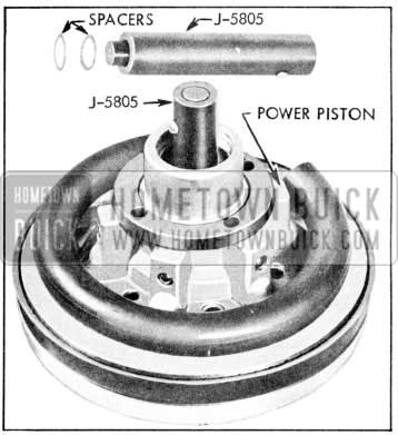
1957 Buick Checking Spacer Thickness
CAUTION: Hydraulic master cylinder piston must be at lowest limit for correct use of gauge. Do not hold assembly by hydraulic piston or allow hydraulic piston to contact bench.
- If pin is flush with body or sticks out no more than .010″, spacers are correct. If pin is high or low, add or remove spacers respectively until within Iimits. When spacers are correct, pull out gauge and set spacers and snubber on air valve. Then set air valve return spring in end of air valve. Install new 0-ring in narrow groove of air valve and lubricate O.D. of air valve and 0-ring. See Figure 9-22.
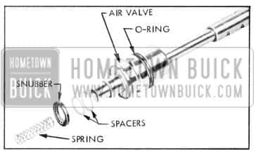
1957 Buick Air Valve and Spacers
Leave A Comment
You must be logged in to post a comment.