The radios for 1957 have been redesigned for clearer and better reception, greater stability of operation and improved appearance. The heater, defroster and air conditioner have been redesigned for 1957 to provide improved performance, easier servicing and more uniform temperature control.
11-1 RADIO
General Description
Clearer and better reception for 1957 has been obtained on all Buick radios-both Wonder Bar and Sonomatic-through relocation of the radio grille in the top center of the instrument panel.
All 1957 radios will make use of printed wiring circuits for increased reliability of circuit assembly and greater stability of Operation, and will have newly designed chrome knobs, push buttons and tuning dials.
Wonder Bar Radio
This radio replaces the Selectronic radio used in prior years. It incorporates manual, push button, automatic push-bar, and automatic foot-switch tuning. The pushbutton feature is the same as the one used in past model Sonomatic radios.
The automatic tuning feature is a greatly improved version of the past model Selectronic radio. These improvements for 1957 provide a more compact, quieter operating, more trouble free radio.
Sonomatic Radio
For 1957 the basic Sonomatic radio mechanical operation remains the same as for 1956, with improvements made in the tuner, the use of printed wiring circuits and new knobs, pushbuttons and tuning dial.
11-2 HEATER AND DEFROSTER
Heater and Defroster Controls
The improved and redesigned heater and defroster for 1957 have their controls styled into the completely new instrument panel rather than below the panel as in 1956.
A single “Air Control” Iever adjusts defrosting and heating or a combination of the two. As this Iever is moved down from the “Off” position, the defroster valve begins to open and is completely open when it reaches the “Def” position. With further downward movement of this Iever, the defroster valve begins to close and the heater valve starts to open. See Figure 11-1.
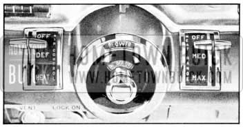
1957 Buick Heater Control
Here, the heater and defroster are operating as a unit. Full down or “Heat” position closes defroster completely and opens heater fully. A second Iever labeled “Heat Range” operates the Ranco valve for automatic temperature control.
Between these two Ievers, in the center of a round bezel, is the blower switch. The movement of this switch is rotational. When air conditioning equipment is installed, the defroster and heater control is located inside this bezel with the blower switch and its movement is also rotational.
Heater Core Inner Housing
As in 1956, hot water enters the bottom of the heater-defroster core and leaves at the top. Air passing through the top of the core does not pick up as much heat as that passing through the bottom of the core, as the heat is removed from the water as it passes up through the core.
Therefore, the new inner heater housing is designed to take defroster air from the upper portion of the core, thus allowing sufficient hot water for heating. When the Ranco valve is regulating temperature and reducing water flow, the temperature differential between the air passing through the top and bottom of the core increases.
With this design, upper level temperature may be reduced as much as 10° but floor temperature remains the same. For improved temperature control, the engine water passes through the Ranco valve before going to the heater core rather than after as was the case at the start of 1956 production.
Heater Air and Defroster Outlets
For 1957, the heater air outlets remain at the outer ends of the instrument panel but are permanently adjusted so that air is directed downward and toward the rear of the car. When an Air Conditioner is installed, then these outlets are of an adjustable type, thereby allowing directional control of the air or heat flow. Also, on Air Conditioner equipped cars, a center outlet is located in the rear edge of the upper instrument panel. Defroster performance has been improved by providing better air distribution to the windshield through two new defroster nozzles. This was accomplished by the design of the nozzle shape and their angle relative to the windshield.
11-3 AIR CONDITIONER
General Description
In 1957, air conditioner equipment has been improved throughout and continues as optional equipment on all models in all Series.
As in 1956, a field installation kit will be made available. Specific instructions for kit installation will be covered in subsequent service information.
With the exception of the changes noted below, the operation, air flow, etc. are similar to those of the 1956 air conditioner.
Component Changes
- The 1957 air conditioner condenser has been increased 1 1/2″ in width to provide greater surface area, thus giving greater condensing capacity.
- Receive-r-Dehydrator. A larger reservoir for the liquid refrigerant has been provided by increasing the size of the receiver-dehydrator.
- With the exception of the pulley drive, the same compressor as used in 1956 is used in 1957 air conditioning equipment. For 1957, a single compressor drive belt is used. This belt passes over the water pump and the crank shaft pulleys but not over the generator pulley as in previous years. This allows an independent compressor drive with belt adjustment taken in the adjustable compressor mounting brackets.
- Hot Gas By-Pass Valve. The hot gas by pass valve has been relocated on the front compressor bracket for 1957. This provides for elimination of the hissing noise of the valve through the dash, better sealing, and more convenient location for servicing or adjusting the valve. See Figure 11-2.
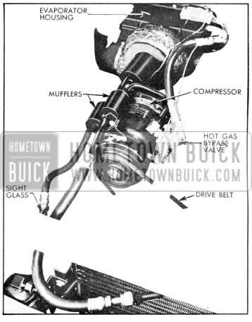
1957 Buick Compressor and Hot Gas By-Pass Valve
Interior Outlets
The completely new outboard outlets for 1957 are more flexible in directional control and pro vide more air at higher velocity, thus assuring cool comfort throughout the entire car.
The center outlet has been moved from the top to the rear upper portion of the instrument panel. It has been redesigned to blend into the new instrument panel and may be closed to increase air flow from the outboard outlets. As in 1956 this valve must be closed for efficient heater Operation.
Air Conditioner Controls
Controls for the air conditioner have been completely redesigned and relocated in the instrument panel. When air conditioning is in stalled, the heater and defroster control lever becomes the cold range control lever, and the heater and defroster air control is mounted inside the bezel with the blower switch. The motion of this heater and defroster control is rotational. See Figure 11-3.
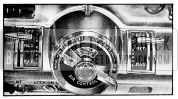
1957 Buick Air Conditioner Controls
The right hand outside air vent knob and control wire is replaced with a dummy knob when air conditioning is installed.
To place the unit in operation, the heater defroster air control is turned to the “On” position, thus engaging the compressor clutch. The heater temperature control is turned to the “Off” position, closing the Ranco valve. The blower switch is moved to either “high” or “low” as required. Temperature is adjusted by the setting of the cold range control.
11-4 WINDSHIELD WASHER AND WINDSHIELD WIPER CONTROL ASSEMBLY
The windshield washer assembly has been relocated and is mounted on the right front fender skirt.
All cars equipped with windshield washers are also equipped with Cam-0-Matic wipers. The Cam-0-Matic control has been altered. In stead of being controlled by a separate knob on the control assembly, it is controlled by the On-Off knob through the same Bowden wire that turns the wiper motor on and off. To turn wiper on, push control knob half-way; any movement beyond half-way controls the wiper sweep. See Figure 11-4.
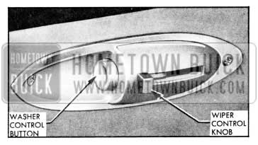
1957 Buick Windshield Wiper and Washer Controls
A check valve assembly, which is an integral part of the wiper motor, has been added due to the introduction of the new type vacuum pump. There are two sources of vacuum for the wiper motor; one source is the intake manifold, and the other source is the new vacuum pump. The function of the check valve is to shut off the vacuum supply from either the intake manifold or the vacuum pump, whichever has the lower vacuum. See Figure 11-5.
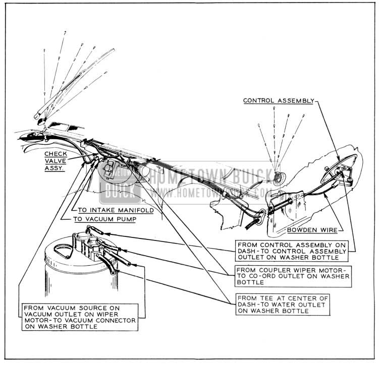
1957 Buick Windshield Wiper and Washer Installation
Leave A Comment
You must be logged in to post a comment.