3-1 FUEL TANK
A new fuel tank is used in all 1957 series, having its filler neck located at the center of the rear bumper. The new fuel tank incorporates a replaceable type fuel strainer located at the bottom of the tank, at the outlet. See Figure 3-1.
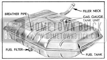
1957 Buick Fuel Tank
To clean or replace fuel strainer, remove the assembly from tank and allow gas to drain. The strainer may be removed from the plug for cleaning.
Synthetic rubber fuel lines with non-corrosive fittings are used on all series. By incorporating the fuel strainer in the tank and utilizing the synthetic fuel lines the possibility of rust and foreign residue entering the carburetor is virtually eliminated and no filter is necessary at the carburetor. See Figure 3-2.
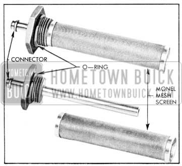
1957 Buick Fuel Strainer
3-2 FUEL PUMP
A new single diaphragm fuel pump is used on all 1957 series, since the vacuum power for the windshield wipers is now derived from the new combination oil and vacuum pump. The new inverted fuel pump is placed lower in a cooler location which reduces the possibility of vapor lock. See Figure 3-3.
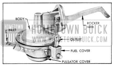
1957 Buick Fuel Pump
3-3 CARBURETORS
The 2-barrel carburetors for 1957 are un changed except for a modification of the air horn to accommodate the new air cleaner and silencer mounting. The 4-barrel carburetors are functionally unchanged, but will have a lower over-all silhouette with the automatic choke housing located on the throttle body.
Specifications for the 1957 carburetors will be covered in future BPS bulletins.
Two 2-barrel carburetors will be used on the 40 Series Dynaflow engine. They are the Carter WGD Mod el 2536S, and the Stromberg WW-2 Model 7-106. Also a special 2-barrel Carter WGD Model 2529S will be used on the 40 Series synchromesh engine. Two 4-barrel carburetors will be used on the 50-60-70 Series engines. They are the Rochester, Part No. 7010070, Model 4GC, and the Carter AFB Model 2507S.
3-4 AIR CLEANER AND INTAKE SILENCER
A new air cleaner is used on all 1957 series. All series use the same type air cleaner, with the only difference being in the carburetor connector tubes which are shaped to fit either the 2-barrel or the 4-barrel carburetor. The element is redesigned to match the increased requirements of the new engine, and to allow clearance for the new lowered hood and body. See Figure 3-4.
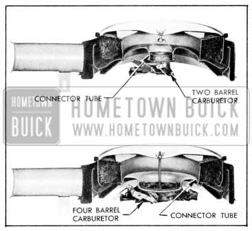
1957 Buick Air Cleaner
3-5 INTAKE AND EXHAUST SYSTEMS
lntake and Exhaust Systems
The intake and exhaust manifold systems have been increased in area for the purpose of obtaining easier breathing.
Muffler
The mufflers are basically the same as for 1956 with the exception that the muffi.ers will be of two-piece construction in order to clear the new underbody. See Figure 3-5.
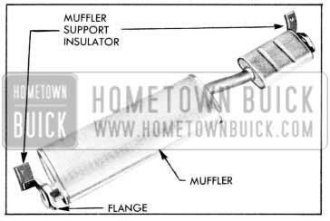
1957 Buick Muffler
Tail Pipes
The dual exhaust tail pipes have been in creased in diameter and will be equipped with resonators located in the rear fenders. See Figure 3-6.
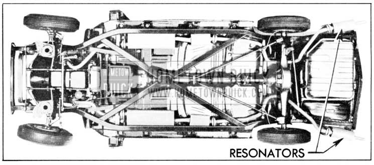
1957 Buick Dual Exhaust System
3-6 THROTTLE LINKAGE
Throttle Linkage Adjustment
The throttle linkage adjustments for 1957 remain the same as for 1956 except for Par. 3-9a, step 5, which is changed to the following: On Dynaflow cars only, disconnect stator control rod from idler at rear end. If this is not done, incorrectly adjusted stator Iinkage might keep accelerator from contacting floor mat as required, or might prevent throttle from returning to hot idle position.
Stator Linkage Adjustment
Adjust stator linkage only after throttle linkage adjustment has been made.
- With throttle held in wide open position, adjust upper stator control rod so its rear end will just slip freely into idler with idler in for ward position.
- Lengthen stator control rod one turn. This provides a slight clearance at stator control valve stop in Dynaflow to make sure carburetor will reach wide-open throttle.
- Reconnect stator control rod at idler and tighten lock nut.
Leave A Comment
You must be logged in to post a comment.