SECTION 10-B BATTERY
10-7 BATTERY
A new Delco-Remy battery, model 562, is used in all 1957 series. It is a 6 cell, 11 plates per cell battery with a 70 ampere-hour rating. This new battery, when used in conjunction with the improved 1957 cranking motor, increases cranking time from 85 to 120 seconds (at -10° F.) for improved low temperature starting, as well as providing more reserve output for accessories when the engine is idling or stopped.
SECTION 10-C GENERATING SYSTEM
10-8 GENERATOR
For 1957, the generator used in all 1956 (after jobs) is carried over for all series with the exception of a smaller pulley for increased low speed output. Due to the change in the generator fields for 1956 (after jobs), test specifications are changed and are listed in Paragraph 10-2 of this manual. Overhaul procedures, however, are unchanged from those used in 1956.
10-9 GENERATOR REGULATOR
To accommodate the 1957 generator, the regulator used for all 1956 (after jobs) will be carried over and specifications for this regulator will apply to all 1957 regulators.
SECTION 10-D CRANKING (STARTER) SYSTEM
10- 10 CRANKING MOTOR
The 1957 cranking motor is an enclosed shift Iever type unit with improved cranking speeds. The drive housing is extended to enclose the entire shift Iever mechanism and solenoid plunger, thus protecting them from exposure to road dirt, icing conditions and splash. This eliminates the need for the splash pan used in 1956. The shift Iever return spring is a compression type and is located between the armature and the collar of the clutch drive. This assist spring aids the solenoid in overcoming the return spring force in the first movement of the clutch along the armature shaft. See Figure 10-1.
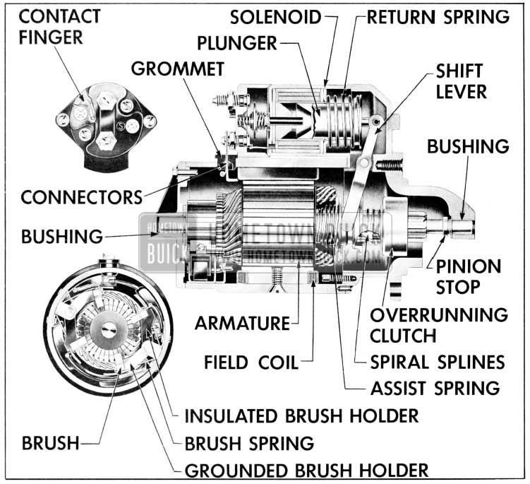
1957 Buick Cranking Motor (Sectional View)
10-11 CRANKING MOTOR REPAIRS ON BENCH
Disassembly, Cleaning and lnspection
When it is necessary to disassemble cranking motor for any reason, make a complete clean-up and inspection to make sure all parts are in satisfactory condition. See Figure 10-1 for identification of parts.
- Remove field lead connecting screw from motor terminal on solenoid.
- Remove two thru bolts and remove commutator end frame and field frame assembly.
- Pull out brush holder pivot pin and remove the two brush holders and springs as a group. Remove screws attaching brushes and Ieads to holders.
- Remove armature and drive assembly from drive housing. Remove thrust collar from pinion end of armature shaft, and remove leather thrust washer from opposite end of shaft.
- To remove drive assembly from armature, place a metal cylinder of proper size 1/2″ pipe coupling will do) over end of shaft to bear against the pinion stop retainer. Tap retainer toward armature to uncover snap ring. Remove snap ring from groove in shaft, then slide retainer and pinion drive assembly from shaft. Remove assist spring. Remove two screws holding solenoid to drive housing and remove solenoid. Remove small nut and insulating washer from the solenoid “S” terminal. Remove large nut and insulating washer from the solenoid battery terminal. Then remove two screws that attach switch cover to solenoid and remove cover for inspection of switch parts.
- Remove shift Iever fulcrum holt and remove shift Iever, plunger and return spring.
- Clean all parts by wiping with clean cloths. The armature, field coils, and drive assembly must not be cleaned by any degreasing or high temperature method. This might damage insulation so that a short or ground would subsequently develop, and will remove lubricant originally packed in the over-running clutch so that clutch would soon be ruined.
- Carefully inspect all parts for wear or damage and make necessary repairs or replace unserviceable parts. Any soldering must be done with rosin flux; never use acid flux on electrical Connections.
- Test armature and make necessary repairs or turn commutator if required.
- Assembly of Cranking Motor
- Lubricate shift Iever linkage and install drive housing.
CAUTION: Never lubricate solenoid plunger or plunger cylinder.
- Assemble solenoid by reversing the disassembly procedure. Install return spring. Apply sealing compound on both sides of solenoid flange where it extends between drive housing and field frame. Then install solenoid.
- Lubricate armature shaft with light engine oil. Install assist spring; then install drive assembly with pinion outward.
- Slide pinion stop retainer down over shaft with recessed side outward.
- Place a new snap ring on drive end of shaft and hold it in place with a hard wood block. Strike block with hammer to force snap ring over end of shaft, then slide the ring down into groove in shaft.
- Place thrust collar on shaft with shoulder next to snap ring, and move the retainer into contact with ring also. Using pliers on opposite sides of shaft, squeeze retainer and thrust collar together until snap ring is forced into the retainer.
- Lubricate drive housing bushing with light engine oil and install armature and drive assembly in housing.
- Continue with assembly of cranking motor by reversing disassembly procedure. If field coils were removed from field frame, use care in tightening pole shoe screws to avoid distortion of parts and make sure that screws are securely tightened.
- Position field frame assembly over armature assembly so that dowel pin engages hole in drive housing. Use care to prevent damage to brushes and brush holders. Make sure that brushes are properly seated on commutator.
- Before installation of commutator end frame, attach a spring scale at each brush and check the pull required to just lift brush off commutator. Brush spring tension should be 40 to 70 ounces.
- Install leather thrust washer on commutator end of armature assembly. Lubricate bushing commutator end frame with light engine oil and install end frame.
- Install thru bolts and tighten securely. Connect field Iead to motor terminal of solenoid with connecting screw.
10-12 CHECKING PINION CLEARANCE
Whenever the cranking motor is disassembled and reassembled, the pinion clearance should be checked. This is to make sure that proper clearance exists between the pinion and the pinion stop retainer when pinion is in cranking position. Lack of clearance would prevent solenoid starter switch from closing properly; too much clearance would cause improper pinion engagement in ring gear.
- Connect a source of approximately 6 volts (3 battery cells or a 6 volt battery) between the solenoid “S” terminal and ground.
CAUTION: Do not connect the voltage source to the “R” ignition coil terminal. Do not use more than 6 volts or the motor will operate. As a further precaution to prevent motoring, connect a heavy jumper wire from the solenoid motor terminal to ground.
- After energizing the solenoid, push the pinion away from the stop retainer as far as possible and use feeler gauge to check clearance between pinion and retainer. See Figure 10-2.
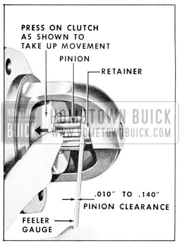
1957 Buick Checking Pinion Clearance
NOTE: Pinion clearance cannot be adjusted. lf clearance is not correct, motor must be disassembled and checked for the above mentioned defects. Any defective parts must be replaced.
SECTION 10-E IGNITION SYSTEM
10-13 IGNITION DISTRIBUTOR
General Description
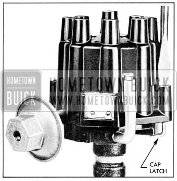
The new ignition distributor for 1957 is of the external adjustment type. See Figure 10-3.
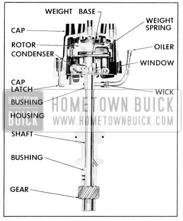
1957 Buick Distributor and Cap Assembly
The distributor is mounted on top of the engine crankcase at the rear end. It is driven clockwise directly from the camshaft through cast iron gears which are automatically lubricated by the engine oiling system. The cap has a window for adjusting point opening while the cap is in a mounted position, and the engine is idling. See Paragraph 10-14c for adjustment procedure. The distributor is of the single contact type with an 8-lobe cam. High speed operation is improved by an especially light contact breaker arm and a high speed cam. Maximum Operating efficiency of the engine is obtained under all speeds and load conditions by the centrifugal advance mechanism, which is located above the circuit breaker cam inside the rotor and the vacuum advance mechanism built into the distributor. See Figure 10-4 and 10-5.
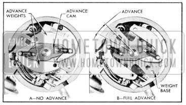
1957 Buick Centrifugal Advance Mechanism
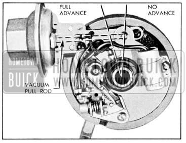
1957 Buick Vacuum Advance Mechanism
Contact Point Set
The contact point set is replaced as one complete assembly. The service replacement con tact set has the Breaker Lever Spring Tension and Point Alignment adjusted at the factory. Only the Point Opening requires adjusting after replacement.
10-14 REPLACEMENT AND ADJUSTMENT OF DISTRIBUTOR CONTACT POINT SET
When inspection of the contact points shows replacement to be advisable, the following procedure should be used.
NOTE: The service replacement contact point set has the breaker spring tension and point alignment adjusted at the factory.
Removal
- Remove distributor cap by inserting a screwdriver in upper slotted end of cap retainers, press down and turn 90° in either direction. See Figure 10-6.
1957 Buick Removing Distributor Cap
Push distributor cap aside and remove rotor. Disconnect the condenser and primary Ieads from their terminal by loosening the retaining screw. Remove condenser screw, lock washer, condenser and bracket.
Installation
- Place contact point set over boss on breaker plate, aligning the two screw openings in contact point base with the two in the breaker plate. Secure with two screws and lock washers.
- Check condenser in a reliable condenser tester. Position condenser and bracket over bosses on breaker plate. Then secure with screw.
- Install condenser and primary Ieads as shown in Figure 10-7.
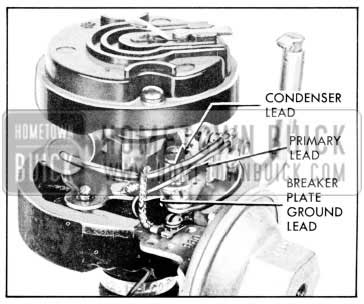
1957 Buick Locating Leads in Distributor
NOTE: Leads must be properly positioned to eliminate interference between cap, weight base and breaker advance plate.
- With contact arm rubbing block on peak of cam lobe, insert a 1/8″ Allen wrench in adjusting screw and turn screw in (clockwise) until contact points just close. Then back screw out ( counterclockwise) 1/2 turn (180° ) to obtain a point gap of approximately .015″ for a preliminary setting.
- Adjustment of Contact Points-Engine Running
NOTE: When adjusting contact point dwell angle, always follow the instructions which come with the dwell meter.
- Connect Dwell Tester Ieads: Red to distributor side of coil, black to ground.
- Turn selector switch to position for 8-lobe cam. Turn ignition switch on.
- Start engine. Lift adjustment window and insert 1/8″ Allen wrench in adjusting screw. See Figure 10-8.
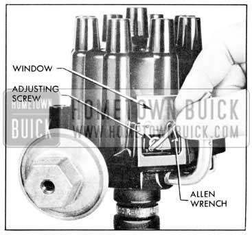
1957 Buick Adjusting Contact Point Dwell Angle
Set dwell angle at 30 degrees.
10-15 REMOVAL, DISASSEMBLY, ASSEMBLY AND INSTALLATION OF DISTRIBUTOR
- Removal and Disassembly of Distributor
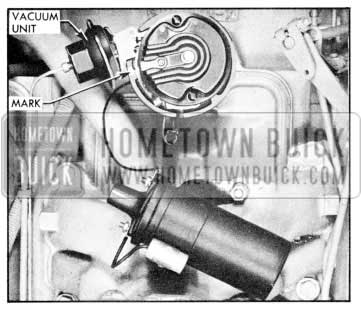
- Disconnect the distributor primary wire from coil and disconnect pipe from vacuum unit. Remove distributor cap by inserting a screwdriver in upper slotted end of cap latches; then press down and turn 90° in either direction.
- Make a mark on distributor base in line with rotor. Then carefully note the location of the vacuum unit in relation to engine so that the distributor can be replaced in the exact same position after it is serviced.
CAUTION: lf engine is turned over while distributor is out, complete ignition timing procedure must be followed.
- Remove distributor clamp and Iift distributor out of crankcase.
- Remove rotor from end of distributor shaft by removing two attaching screws, lock washers, and flat washers.
- Mark distributor shaft and gear so that they may be reassembled in same position.
- File or grind staking from driven gear pin and drive out pin, using hammer and punch.
CAUTION: DO NOT damage distributor shaft when driving the pin out.
- Slide gear off shaft and pull shaft, breaker cam, and centrifugal advance mechanism from housing.
- Remove two weight springs and both advance weights. Slide the integral weight base plate and distributor cam off the shaft.
- Remove contact point set from breaker plate by first removing primary and condenser Ieads from contact set terminal by loosening the screw. Then remove the two attaching screws which hold the base of contact point assembly in place. Remove condenser and bracket.
- Remove snap ring from upper bushing and Iift breaker plate and felt wick from upper bushing.
- Remove two retaining screws and vacuum advance.
- Remove O-ring seal from shaft housing.
NOTE: No attempts should be made to service the shaft bushings in the housing as the housing and bushings are only serviced as a complete assembly.
- lnspection of Distributor Parts
- Wash cam and housing assembly in clean solvent, holding housing horizontal to avoid getting cleaning solvent into lubricant reservoir. Dry parts thoroughly.
- Inspect distributor cam and replace if lobes are scored or excessively worn.
- Inspect shaft for excessive looseness in bushings in distributor housing. Also, check fit of breaker plate on O.D. of upper main bearing. Inspect distributor gear for wear or scoring of teeth.
- Examine distributor cap and rotor for cracks and dirt. Inspect cap inserts for oxidation.
- Inspect ground and terminal connector Ieads and replace if they are oil soaked, if strands are broken, or if terminals are loose.
- Test condenser if a reliable condenser tester is available.
- Examine contact points for excessive wear. pitting or burning. Inspect breaker arm spring for cracks and rubbing block for wear or looseness.
- Assembly and Installation of Distributor
NOTE: The first five steps apply only if the distributor has been completely disassembled.
- Install distributor primary lead and rubber grommet. Install vacuum advance unit with ground Iead terminal from breaker plate under outer mounting screw and lock washer.
- Install felt washer over upper bushing and apply a few drops of light oil. Then place breaker plate over upper bushing and vacuum advance link. Install retainer on upper bushing. See Figure 10-9.
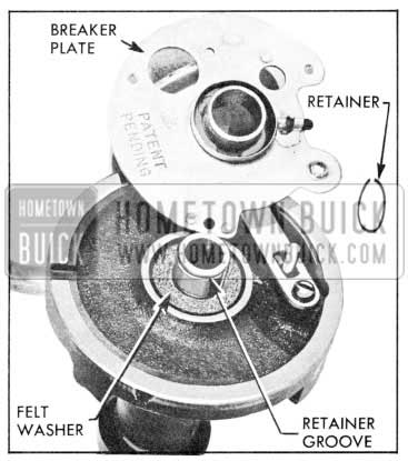
1957 Buick Installing Breaker Plate and Retainer
CAUTION: Excessive grease may throw off into contact points when hot. Petroleum jelly is not suitable for temperature reached by the cam.
- Make the preliminary contact point adjustment ( 10-14,b).
- Install rotor and secure with two screws, lock washers, and plain washers. NOTE: The square and round lugs on the bottom of the rotor must be positioned in the corresponding holes in the weight base plate. See Figure 10-10.
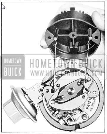
1957 Buick Installation of Rotor
1957 Buick Installing Distributor in Engine
1957 Buick Installing Spark Plug Wires – Left Bank
1957 Buick Installing Spark Plug Wires – Right Bank
Wires must be pushed all the way down into the distributor cap terminals and onto the spark plugs. Nipples must be pushed firmly over the terminals and boots over the spark plugs.
NOTE: lf engine was accidentally turned over while distributor was out, complete ignition timing procedure must be followed.
10-16 SPARK PLUG WIRES
Description
Resistance-type spark plug wires are used on all 1957 series. This new wire eliminates the need for an additional radio suppressor in the circuit such as the resistor used in the distributor rotor on previous models.
This resistance-type wire is not serviceable, and if damaged, the complete wire or assembly must be replaced.
The sheet metal spark plug covers have been eliminated. A new spark plug boot is introduced in all 1957 models which prevents foreign matter from accumulating in the spark plug wells, as well as insulating the spark plug terminal and keeping the spark plugs dry.
Installation
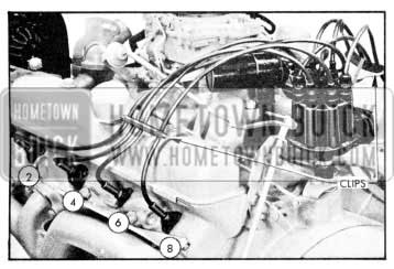
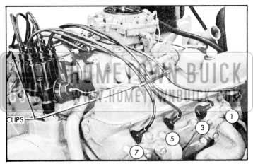
Spark plug wires must be arranged to pass through the wire clips on the rocker arm covers in the same order as they are attached to the spark plugs. To insure correct arrangement in the clip, the spark plug wire numbers are stamped in the upper surface of the clip. If spark plug wires are not correctly installed, missing or cross-firing may result. See Figures 10-12 and 10-13.
No. 1 spark plug is installed in the distributor cap terminal just forward of the vacuum advance unit. The other wires are then installed in a clockwise direction according to the firing order, 1-2-7-8-4-5-6-3. See Figure 10-14.
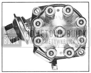
1957 Buick Installing Spark Plug Wires in Distributor Cap
SECTION 10-F LIGHTING SYSTEM
10-17 REAR LICENSE LAMPS
All series are equipped with two rear license plate lamps for improved illumination.
10-18 TAIL AND STOP LIGHTS
The new tail lamp assembly has the taillight located in the upper section, directional signal and stop light in the center section and the back-up light in the lower section of the assembly.
10-19 INSTRUMENT PANEL LIGHTS
Ignition Lock Light
The ignition lock light is located above and between the ignition lock and the cigar lighter and operates any time the instrument panel lights are on.
Heater Control Lights
The heater air and temperature controls, blower switch and air conditioner controls are equipped with plastic lenses having white lettering over a black background and are illuminated from behind. These controls are illuminated whenever the instrument panel lights are on.
Light Switch Light
The light switch escutcheon is illuminated from behind in the same manner as the heater controls.
Dynaflow Control Dial Light
The Dynaflow control dial is illuminated from behind in the same manner as the heater controls and light switch and is equipped with a red pointer. The bulb is installed behind the instrument panel below the instrument duster.
SECTION 10-G SIGNAL SYSTEMS
10-20 HORN
The horns for 1957 are of the solenoid type rather than the vibrator type previously used and embody a simpler, more rugged construction. See Figure 10-15.
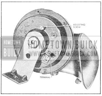
1957 Buick 1957 Horn
To check the current adjustment of the horns, measure the current draw on the horn while the horn is operating. The low note horn (identified by an odd number in the last digit of the model number) and the high note horn (identified by an even number in the last digit of the model number) should have a current draw of 8.0-10.0 amperes at 11.5 volts. The horn tone is built into both high and low toned horns and current draw is the same for both.
To make current adjustment, turn adjusting screw clockwise to decrease current, and counterclockwise to increase current.
Circuit checks for malfunctioning operation are the same as for previous models.
10-21 DIRECTION SIGNAL SWITCH
Description
A new switch and switch operating control are used on all 1957 series. The circuit switch is now located on the mast jacket directly below the instrument panel; however, the redesigned cancellation mechanism and switch operating lever is still located between the steering wheel and the gear shift control housing. The circuit switch is activated by the Operating control through a Bowden wire. The directional signal wires coming from the body and chassis wiring harness are connected directly to the circuit switch.
- Timing of Directional Circuit Switch
- Place actuating Iever in its normal “off” position.
- Loosen bolts holding circuit switch to steering column jacket.
- Move switch on jacket until pin is centered and a loop of wire is visible on each side of pin, as viewed through the opening at the bottom of the switch.
- Tighten bolts and recheck position of pin.
SECTION 10-H INSTRUMENTS AND CLOCK
10-22 INSTRUMENT PANEL
The instrument panel for 1957 has been completely redesigned with all instruments and controls grouped more directly in front of the driver to give improved visibility and better access to controls. The glove box is now nearly centered in the instrument panel. The clock and radio are in approximately the same position as in the 1956 models.
The upper part of the instrument panel can be removed for servicing of instruments, controls, clock and radio.
The instrument duster is shorter in length and the ammeter, temperature gauge, oil pres sure gauge and gasoline gauge are lined up horizontally and directly above the speedometer. The odometer is located below the speedometer as in 1956.
On all cars equipped with the 1957 Safety Group, a “Safety-Minder” is included. This is a device, attached in conjunction with the speedometer, which may be set at a specific speed, and as soon as the car exceeds this speed, a buzzing sound begins and continues until the speed is reduced below the setting. The speed setting is adjusted by turning the accessory switch and is indicated in a window in the lower left hand corner of the speedometer.
All gauges for 1957 will have a black back ground with white lettering and red pointers instead of the color scheme used in the 1956 models.
The light switch is located in the center of a bezel to the left of the driver and the blower switch in the center of a bezel to the right.
Two Ievers, one on each side of the right bezel control the heater-defroster air flow and heat range.
On cars equipped with air conditioning, the heater-defroster control is mounted in the center of the bezel with the blower switch. The cold control range is placed in the former location of the heater-defroster air control lever.
The accessory switch, emergency brake light, and left vent control are located just to the left of the steering column on the lower part of dash, while the right vent control, ignition lock, and lighter are located on the right.
The accessory switch operates the power top on convertibles and can be used for optional electrical accessories on other models.
The windshield washer and wiper controls are mounted on the left trailing edge of the upper portion of the instrument panel with a Iever to operate the wiper and a button for the washer.
10-23 CLOCK
A new clock with a sweep-second hand and automatic regulation will be available as optional equipment for all series. Each time the clock is reset, the regulator will move automatically toward fast or slow, provided the reset knob is rotated in the direction the hands must move to correct the clock setting. A counterclockwise turn of the reset knob will make the clock run slower and a clockwise turn will make the clock run faster. This feature permits the operator to regulate the clock automatically by resetting the hands to the correct time.
The change in regulation will be approximately 20 seconds per day for a change in hand-setting of five minutes or more. A mechanical Iockout has been installed on the automatic regulator control which prevents the regulator from operating more than twice in any 12 hour period.
SECTION 10-1 WIRING CIRCUIT DIAGRAMS
10-24 FUSE BLOCK
By using the new direction signal switch as a wiring junction some of the connections formerly used on the fuse block have been eliminated; therefore, a smaller fuse block is used on all 1957 models. The new fuse block, which is mounted in approximately the same position as in previous models, has a spring clip retainer replacing the two bolts formerly used.
10-25 WIRING HARNESS
On all 1957 models the portion of the chassis wiring located under the dash is now a separate harness and joins the chassis wiring harness through a multiple connector located in the dash. This will facilitate removal and replacement of the wiring harness.
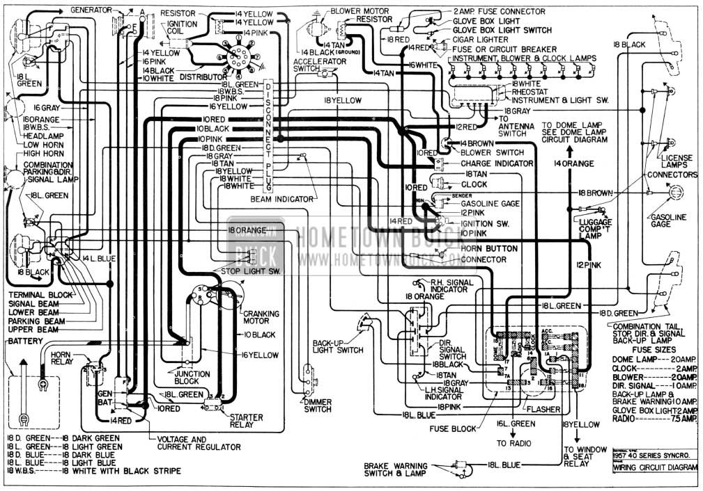
1957 Buick Chassis Wiring Diagram-Synchromesh Transmission
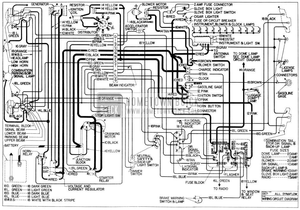
1957 Buick Chassis Wiring Diagram-Dynaflow Transmission
Leave A Comment
You must be logged in to post a comment.