7-1 SPECIFICATIONS
1957 Buick Chassis Specifications
7-2 FRONT END SUSPENSION
Two entirely new features have been incorporated into Buick’s front suspension system for 1957: anti-dive geometry and ball-joint type pivots. To reduce roll, the front stabilizer bar has been increased in diameter from .687″ to .750″. See Figure 7-1.
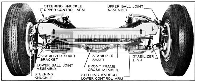
1957 Buick Front Suspension
- Anti-Dive Geometry
- During brake application two forces act on the front suspension. When the brakes are applied, the torque is transmitted to the backing plate and knuckle assembly through the brake shoes, which tends to rotate the backing plate and knuckle assembly forward.
- The weight of the car is thrown forward tending to move the front of the car downward. This downward motion is called “front-end dive”. In order to minimize “front-end dive”, the upper control arm shaft is mounted to the frame so that the front end of the shaft is higher than the rear end at an angle of approximately 14° relative to that of the lower control arm shaft. Thus, when the braking force is applied, the tendency of the car’s front end to dive rotates the backing plate and spindle assembly in a rearward direction, while the braking torque tends to rotate the backing plate and spindle assembly in a forward direction. There fore, the braking torque creates an upward force nearly equal to the downward (diving) force. In this manner, “front-end dive” is held to a predetermined minimum. See Figure 7-1.
- Ball-Joint Type Pivots
In 1957 the king pin and steering knuckle support have been eliminated by the use of the ball-joint type pivots to obtain easier steering and Ionger wear.
The ball-joint assemblies consist of ball and socket joints attached to the upper and lower control arms by mounting tangs and in turn to each end of the steering knuckle by tapered bolts. See Figure 7-2.
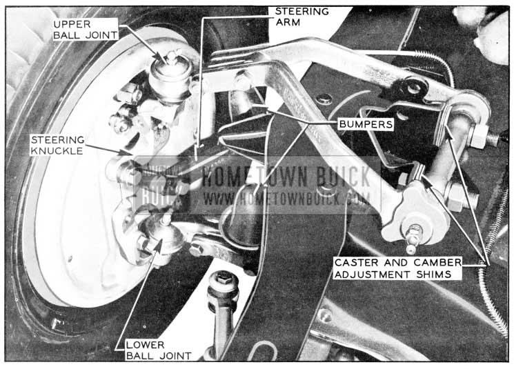
1957 Buick Ball Joint Suspension
Neoprene seals retain grease and prevent moisture and other foreign material from entering the ball-joint assembly.
Adjustments for caster and camber are made with the use of shims between the upper control arm shaft and the support bracket attached to the top of the frame.
7-3 FRONT HUB AND BEARINGS
For added safety and dependability of brake operation, a sheet metal grease trap and a front wheel oil seal of the lip-type are introduced on the 1957 models. This seal runs directly on the shoulder of the spindle. See Figure 7-3.
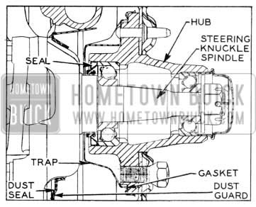
1957 Buick Front Wheel Oil Seal and Grease Trap
7-4 FRONT SHOCK ABSORBERS
The front shock absorbers for 1957 are basically the same as those used in 1956, except that a mounting eye is used at each end. Thus, to remove the upper end of the shock absorber, it is necessary to remove the upper bolt and nut. If the rubber bushings are not in good condition, the entire shock assembly must be replaced. See Figure 7-4.
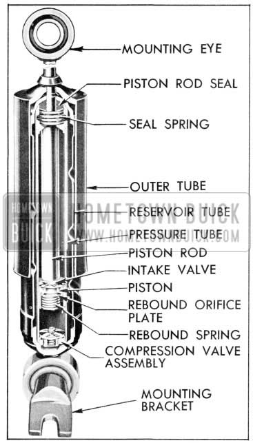
1957 Buick Front Shock Absorber
7-5 RADIUS ROD
The radius rod has been decreased in length by 10.4″ for Series 40 and 60 and by 12.5″ for Series 50 and 70.
7-6 REMOVAL AND INSTALLATION CF BALL JOINTS AND /OR STEERING KNUCKLE
- Removal of Ball Joints and Steering Knuckle
- Jack up car and support weight on front spring seat.
- Remove front wheel with hub and drum assembly.
NOTE: Support wheel assembly carefully during removal to avoid damaging wheel bearing inner seal.
- Remove bolts through backing plate and steering knuckle.
- Remove backing plate from knuckle. Do not remove brake hose. Support backing plate out of way to avoid damage to brake hose.
- Remove bolts through lower control arms and ball joint. Lower steering arm out of the way. Remove rubber bumper from ball joint if ball joint is to be replaced.
- Remove bolts through upper control arms and ball joint. Remove knuckle and ball joint assembly from upper and lower control arms.
- Support securely in vise in a manner that will allow solid blows directly on end of ball joint stud. See Figure 7-5.
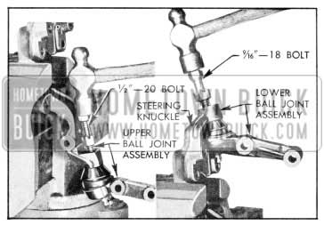
1957 Buick Removing Ball Joints from Steering Knuckle
NOTE: lf ball joints are to be re placed , remove nuts and drive on studs to remove. lf knuckle is to be replaced and ball joints are to be re- installed, care must be taken to avoid damage to threads. Loosen nuts on tapered studs and install a short bolt half way into nut and tighten. The upper ball joint stud has a 1/2″-20 thread which is the same as a universal joint bolt. The lower stud has a 9/16″-18 thread, the same as a wheel lug bolt.
- Installation of Ball Joints and Steering Knuckle
- Wipe clean and lightly lubricate the tapered surfaces of the ball joints and knuckle. Install joints in knuckle and tap lightly with a hammer. Install nuts and torque upper nut 30-40 ft. lbs. and lower nut 40-50 ft. lbs.
- Position ball joint and knuckle assembly in upper and lower control arms and install bolts.
NOTE: Bumper pad mounts to rear side of upper control arm assembly. Torque bolts to
- 80-90 ft. lbs.
- Install rubber bumper in lower ball joint, if removed during servicing.
- Using a new dust seal, reinstall steering arm and brake backing plate on knuckle.
NOTE : Steering arm to knuckle bolts requite castellated nuts and cottet pins.
- Examine inner wheel bearing seal and grease trap for evidence of damage or leaking. If necessary, install new seal using Hub Oil Seal Installer J-6414.
- Reinstall wheel and hub assembly.
7-7 REMOVAL AND INSTALLATION OF FRONT SPRING
The removal and installation of front springs remains the same as previous models except that the lower ball joint should be disconnected from the lower control arm where the lower pivot pin was formerly removed. Torque bolts to 80-90 ft. lbs.
7-8 REMOVAL AND INSTALLATION OF UPPER CONTROL ARM SHAFT OR ARM AND SHAFT ASSEMBLY
Removal
NOTE: As upper control arms are not furnished separately, their replacement must be made as an assembly.
- Jack up car, supporting car weight on spring seat and remove wheel and tire.
- Remove upper control arm to ball joint bolts, supporting knuckle and brake drum assembly to avoid damage to brake hose.
- Remove shock absorber upper mounting holt and force top of shock absorber down.
NOTE: lf work is being performed on right side it will be necessary to remove generator and generator mounting bracket. (Disconnect battery ground strap.)
- Remove shaft attaching bolts, carefully noting position and number of adjusting shims. Remove arm and shaft assembly from car.
- If upper shaft and bushings only need replacement, clamp arms in vise, and remove old shaft and bushings; then apply a liberal amount of Lubriplate to new bushings and ends of shaft. Install bushings and tighten to 150 ft. lbs. torque.
- Install rubber dust seals on shaft and screw shaft into forward arm to 1 9/16″ (+/- 1/32″) dimension shown in Figure 7-6.
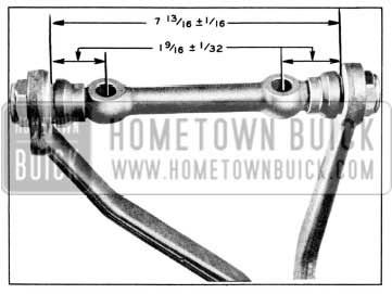
1957 Buick Upper control Shaft Dimensions
Thread rear arm onto shaft to the 7 13/16″ (+/- 1/16″) dimension.
Installation
- Using care not to disturb dimensions obtained in Step 6, install assembly on car by reversing removal procedure. Tighten upper ball joint bolts to 80-90 ft. lbs. torque. Tighten upper shaft to shaft bracket bolts 80-100 ft. lbs.
- Check front wheel alignment and correct as necessary.
7-9 REPLACE LOWER CONTROL ARM ASSEMBLY, SHAFT OR BUSHINGS
These operations remain the same as on previous models except that the lower ball joint should be disconnected from the lower control arm instead of removing the lower pivot pin.
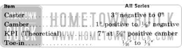
7-10 FRONT WHEEL ALIGNMENT
CAUTION: When checking theoretical king pin inclination, car must be on a level surface, both transversely and fore and aft.
With camber known to be within specified limits, theoretical king pin inclination should check within specified limits given in Figure 7-8.
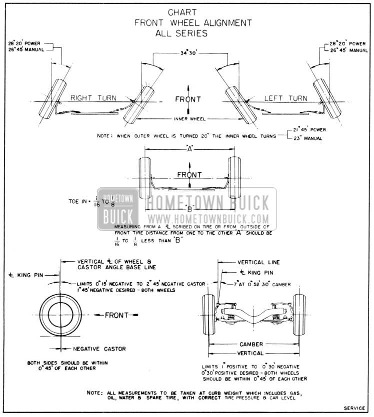
1957 Buick Front Wheel Alignment Specifications
If camber is correct and theoretical king pin inclination is not correct, a bent steering knuckle is indicated.
If camber is incorrect beyond limits of adjustment and theoretical king pin inclination is correct, or nearly so, a bent steering knuckle is indicated.
If camber and theoretical king pin inclination are both incorrect by approximately the same amounts, a bent upper or lower control arm is indicated.
There is no adjustment for theoretical king pin inclination as this factor depends upon the accuracy of the front suspension parts. Distorted parts should be replaced with new parts. The practice of heating and bending front suspension parts to correct errors is not recommended as this produces soft spots in the metal in which fatigue and breakage may develop in service.
Toe-in specifications and adjustment remain the same as in previous models.
CAUTION: The steering knuckle and steering arm “rock” or tilt as front wheel rises and falls. Therefore , it is of vital importance to position the bottom face of tie rod end parallel with machined surface at outer end of steering arm when tie rod length is adjusted. Severe damage and possible failure can result unless this precaution is observed.
Leave A Comment
You must be logged in to post a comment.