4-1 CLUTCH ASSEMBLY
A new type centrifugal weighted clutch pres sure plate is used in 1957. The outer ends of the release Ievers are weighted so that at higher engine speeds where slipping is liable to occur, centrifugal force causes more pressure to be applied on the pressure plate. The faster the clutch revolves, the greater the pressure exerted against the clutch plate, thereby in creasing the torque transmitting ability of the clutch. This additional pressure allows the use of a clutch which requires lower foot pressure at the pedal for normal clutch operation. The diameter of the driven plate is increased from 10.5″ to 11″ increasing the effective area from 106.8 to 113 sq. in. The clutch pressure plate, cover springs and Ievers are serviced as an assembly only. Removal and replacement procedures are the same as used in previous models.
4-2 CLUTCH RELEASE MECHANISM
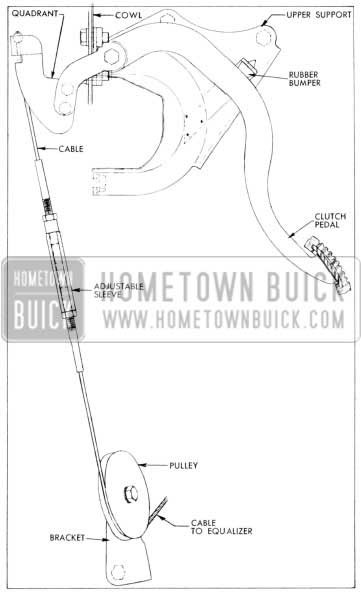
A completely new clutch release mechanism is introduced for 1957. The clutch pedal is the suspended type. It is mounted between hinge brackets which are bolted to the cowl. Pedal position at rest is determined by a pedal bumper mounted on a bumper support which is non-adjustable. See Figure 4-1.
1957 Buick Clutch Release Mechanism
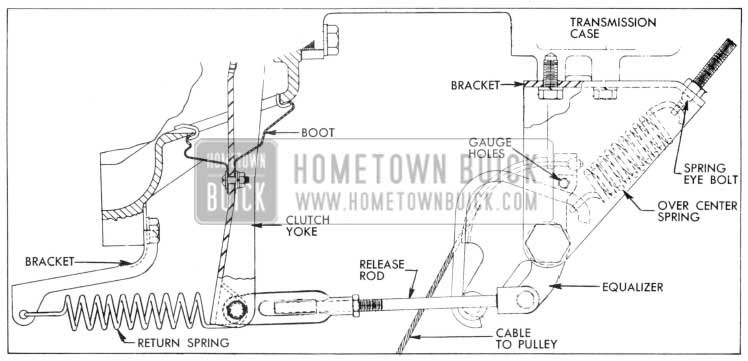
The portion of the pedal beyond the pivot projects through the cowl where a cable quad rant is bolted to it. As the pedal is depressed, the cable quadrant and cable are raised, causing a release equalizer to turn. This rotation of the equalizer pulls the clutch release rod to the rear which in turn pulls the clutch yoke rear ward to disengage the clutch. See Figure 4-2.
1957 Buick Clutch Equalizer Bracket
The pedal pivots on nylon bearings which do not require periodic lubrication. The cable runs over a pulley and is fastened to the equalizer. The pulley is adjustable so it can be aligned with the cable. The cable length is adjustable so that the equalizer can be properly positioned. The correct equalizer position is such that the equalizer over-center spring helps to hold the pedal firmly against the pedal bumper when the pedal is released. However, after the pedal is slightly depressed, the over-center spring helps to reduce pedal pressure. This spring is attached to the equalizer bracket by an eye holt and to a pin on the equalizer by an extension which straddles the pivot point of the equalizer. See Figure 4-2. The equalizer has a fitting which should be lubricated periodically.
The release rod, which extends from the equalizer to the clutch yoke, has an adjustable clevis. The yoke is held on a ball stud by a U-shaped spring riveted to the yoke. A boot around the yoke provides a flexible closure for the yoke opening in the flywheel housing. The inner end of the yoke is in position to push forward on the release bearing when the clutch pedal is depressed. A U-shaped spring riveted to the release bearing holds the bearing in contact with the yoke. The release rod length must be adjusted to provide correct clearance between the release bearing and the clutch release Ievers.
A return spring is connected between the release rod clevis pin and a bracket on the engine to keep the release bearing out of contact with the release Ievers when the clutch is engaged.
4-3 CLUTCH PEDAL LASH ADJUSTMENT
It is very important to maintain proper pedallash (free pedal) at all times. Insufficient pedal lash will cause the release bearing to ride against the release Ievers resulting in abnormal wear of these parts; it may also cause clutch slippage and abnormal wear of the driven plate, flywheel, and pressure plate if pressure on the release Ievers is enough to prevent positive engagement of the clutch.
- Make certain that return spring pulls clutch pedal firmly against pedal bumper when pedal is released. If pedal does not contact bumper, check pedal and linkage for binding or lack of lubrication. Check condition of re lease yoke return spring. Check condition of equalizer over-center spring and make sure that spring eye holt is fully tightened.
- Before making any clutch linkage adjustment, clutch equalizer must be in correct position. Position equalizer by inserting a 1/4″ x 2 1/2″ holt through gauging hole in equalizer from bottom as it lines up with two holes in equalizer bracket. See Figure 4-2. If cable is too loose, pull slack out of cable until holes align; if cable is too tight, tension must be loosened at cable adjusting sleeve until 1/4″ holt will be held in gauging holes.
- Remove release rod adjusting end cotter key and flat washer.
- Remove return spring and release rod to yoke clevis pin.
- Loosen release rod adjusting end jam nut and adjust end until clevis pin fits freely with yoke held to rear.
- Lengthen release rod by rotating adjusting end approximately four complete turns. This will provide proper clearance between clutch release bearing and release Ievers. Pedal lash should be 1%” to 11,4″.
- Replace clevis pin and spring washer.
- Hook return spring over clevis pin. Install flat washer and cotter key.
- Tighten release rod jam nut.
- To tighten cable to proper tension, first clamp locking pliers on both upper and lower cables just off threaded sections to keep cables from twisting.
- Loosen cable adjusting sleeve jam nuts.
- Turn adjusting sleeve clockwise as viewed from top to tighten cable. Cable tension is correct when gauging holt drops or is easily removed from holes in equalizer and equalizer bracket.
- Tighten adjusting sleeve jam nuts. Remove locking pliers. 14. Check pedal lash (free pedal) by pushing on pedal pad with hand. Do not mistake tension of pedal return spring as an indication of Zack of pedallash. Pedal lash should be 11/8″ to 11,4″, measured at pedal pad.
4-4 S-M TRANSMISSION
The Synchromesh transmission for 1957 is basically the same as 1956, except for a more rigid construction and slightly different gear ratios. The different gear ratios are due to a changed ratio between the clutch gear and counter gear giving the following ratios: first, 2.15 :1; reverse, 2.28:1; and second, 1.37 :1. The major changes in construction are:
- Strengthening of the transmission case by additional ribs.
- Lengthening of the rear bearing retainer and output shaft.
- Wider clutch gear, second speed gear and meshing gears on the counter gear for greater strength.
- An additional steel thrust washer between the counter gear and rear bronze thrust washer.
- Increased diameter of main shaft journal which carries the second speed gear.
4-5 U-JOINT AND TORQUE BALL
A slightly larger V-joint having greater strength is used in 1957. To accommodate this change, the torque ball bushing is increased in diameter. The torque ball inner rubber contact ring has also been eliminated and the inner retainer has been modified to accommodate two “0” rings for sealing purposes to eliminate oil leaks at the torque ball.
Leave A Comment
You must be logged in to post a comment.