1953 RADIOS
ALL SERIES
There have been a number of changes in the 1953 radios in both the Series 40, 6 volt and the Series 50-70, 12 volt systems.
Selectronic radios will again be optional equipment on the 1953 models. As before, this radio will automatically seek out and select a station at a touch of the floor control button or the bar on the radio grille panel.
The Series 40 radio, with the 6 volt electrical system, is now equipped with three of the new miniature (peanut) sized tubes. Color and knob designs have also been changed to conform to the 1953 dash.
The Series 50 and 70 radios in the 12-volt system have been materially changed to conform to the 12-volt unit. These radio changes consist of a new 12-volt vibrater, tubes, transformer, pilot light, and a number of the new peanut or miniature tubes.
The 1952 Radio Part No. 980979, which is also used in past models, has been replaced by the 1953 Series 40 Radio Part No. 981329.
When installing Radio 981329 in 1953 and past models, it will be necessary to remove the 3/4″ Hex Nuts on the Volume and Tuning Shafts which are supplied with the Radio. In their place, it will be necessary to install two (2) Group9.649-7262137 Spacer Nuts which will then allow the radio to be positioned properly in the dash.
HEATER HOSE CHECK
ALL BUICKS
We wish to draw attention to the fact that whenever a Buick is winterized, a complete check should be made of all the radiator, heater, and Dynaflow oil cooler hoses, especially at the engine connections.
One of the greatest causes of radiator and heater hose deterioration and subsequent failure is oil. Oil soaking on any rubber hose will shorten its life by one -half. Because of this fact, it is particularly important that all heater and Dynaflow oil cooler hoses on power steering equipped Buicks be carefully checked, especially where they pass under the p6wer steering pump and also at the engine connection and Dynaflow oil cooler hoses at their connections to the oil cooler. Softening and deterioration of these hoses can be easily noted.
RADIO IDENTIFICATION
ALL SERIES
In order to aid in identifying the time and place of manufacture of radios that have required field service, it is requested that all product reports give the model and serial numbers of the radios repaired.
As shown in Figure 97, the model and serial numbers are given on a tag fixed to the bottom of the radio.
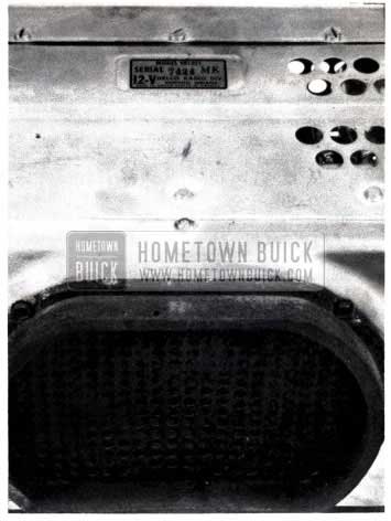
1953 Buick Radio Identification
WIRE WHEEL DISCS
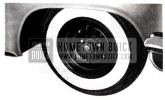
To comply with the increased demand for sports car equipment, Buick has added the new wire wheel discs to its accessory program. These discs, as shown in Figure 98, View A, are similar to the regular detachable wheel discs with the exception that they are bolted directly to the wheels. (This provides a positive position and helps insure against loss or theft.)
1953 Buick Wire Wheel Discs
1953 Buick Wheel
The wire wheel discs are adaptable to all Buick 15″ wheels and may be ordered as follows:
Series 40 – Group 5.858, Part 981434 (6″ wide rim)
Series 50-70 – Group 5.858, Part 981435 (6 1/2″ wide rim)
These numbers are for one wheel or unit only, therefore, if two or four of these discs are desired, it must be stipulated as such on the order. These units or kits will include a wire wheel disc, hub cap, and valve extension.
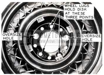
Due to the double taper present on the three wheel bolts securing the wire wheel discs, (See Figure 98, View A), special attention should be given at the 1000 and 2000 mile inspections.
These bolts require the same torque (70 to 75 ft. lbs.) as is used in servicing all wheel lugs with or without wire wheel discs.
When installing the new wheel discs, it is not necessary to remove the wheel from the brake hub. Merely remove three of the wheel bolts from the hub thus leaving two wheel bolts in place to support the wheel (See Figure 98, View B). These two bolts must have one empty bolt hole between them and this hole must be directly below the valve core as shown in Figure 98, View B. This arrangement is necessary due to the outlet hole for the extended valve core in the wire wheel disc.
Using the valve core hole in the wire wheel disc as a guide, insert extended valve core through hole in wire disc and place disc on wheel so that oversize holes (See Figure 98, View A) in disc fit over the two wheel bolts supporting the wheel on the brake drum and then replace the remaining three wheel bolts.
Because the wire wheel discs are balanced, it will usually be unnecessary to rebalance the front wheel after installation.
Leave A Comment
You must be logged in to post a comment.