CARBURETOR SPECIFICATIONS
SERIES 40 SPECIFICATIONS
See Paragraph 3-1 in the 1952 Buick Shop Manual for Series 40 specifications.
SERIES 50-70 GENERAL SPECIFICATIONS
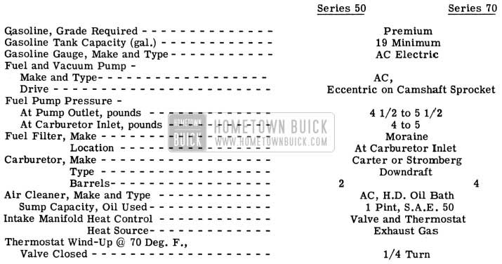
1953 Buick Fuel and Exhaust System Specifications
CARTER CARBURETOR AND CHOKE CALIBRATIONS
IMPORTANT: Calibrations are governed by the CODE number on the attached code tag.
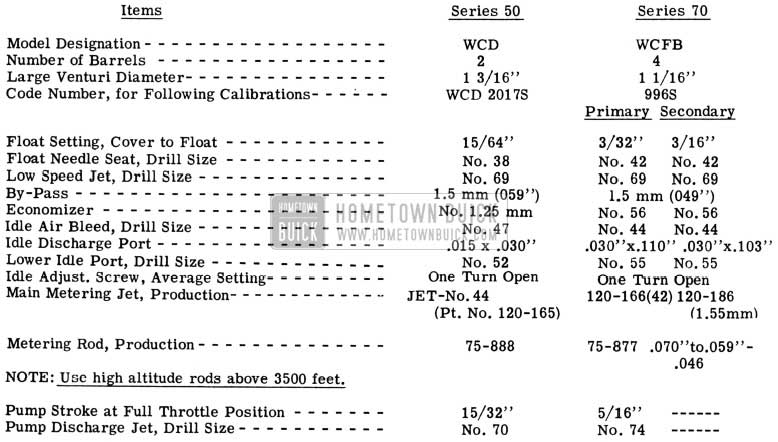
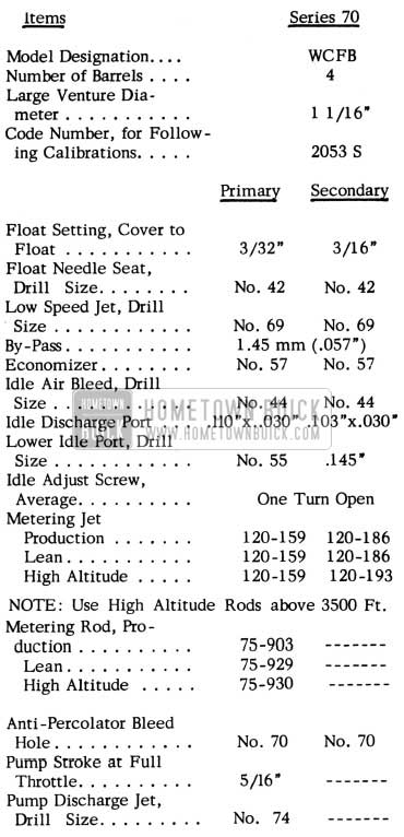
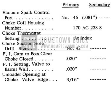
1953 Buick Carter Carburetor Specifications
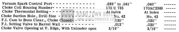
1953 Buick Carter Carburetor Specification
STOMBERG CARBURETOR AND CHOKE CALIBRATIONS
IMPORTANT: Calibrations are governed by the CODE number stamped on air horn directly above the fuel level sight plug.
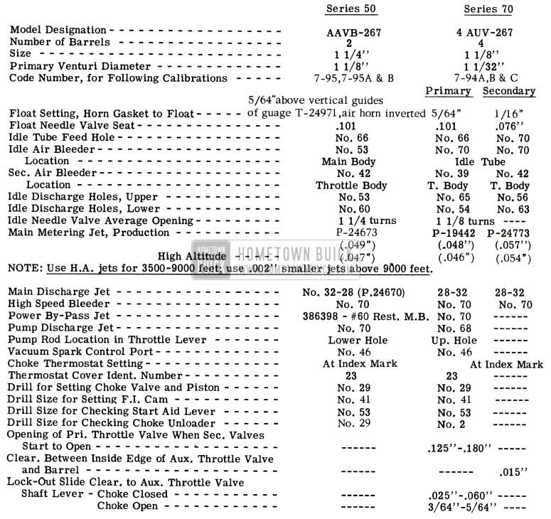
1953 Buick Stromberg Carburetor Specifications
CARBURETOR IDLE SETTINGS
SERIES 50- 70
The question has been brought up regarding the proper idle speeds of the new V-8 engines.
Both the Carter and Stromberg, on a hot idle adjustment should idle the engine a t 450 RPM. However, it is again mentioned that new engines, as they loosen up, will idle faster and faster and therefore, the hot idle must be adjusted accordingly.
The Carter Carburetor has a cold idle setting of 750 RPM corrected to “0” degrees Fahrenheit on a new V-8 engine. It is understood that this condition is difficult to duplicate in the field, therefore, it is suggested that the cold idle be adjusted according to conditions under which the unit must operate.
The Stromberg carburetor does not have a cold idle setting. This is regulated by cam action and therefore, no adjustment is possible.
V-8 ENGINE ACCELERATION HESITATION
1953 SERIES 50 & 70
There are some instances where a new V- 8 engine may have a tendency to hesitate with sudden throttle application when the engine is cold. In most cases this condition can be remedied with a complete and careful engine tune-up. Extreme care must be exercised in this tune-up procedure. Spark plugs should be set at exactly .032 and contact points at .015″to .01i’with the use of the dial indicator. Timing must be set exactly if best results are to be obtained. Closer tolerances in engine settings and adjustments are required due to high performance characteristics of the V-8 engines. In addition, a new phase of engine tune-up will include the checking of the exhaust manifold heat valve to be sure it is free and operating correctly.
Because the intake manifold is so much an independent unit or section of the new V-8 engine, setting two or more inches off the main block, extreme care must be exercised to insure proper heating of its interior as proper carburetion depends largely on heat. Unlike the straight-eight, the V-8’s exhaust manifold heat valve must operate and operate correctly if proper engine performance is to be experienced.
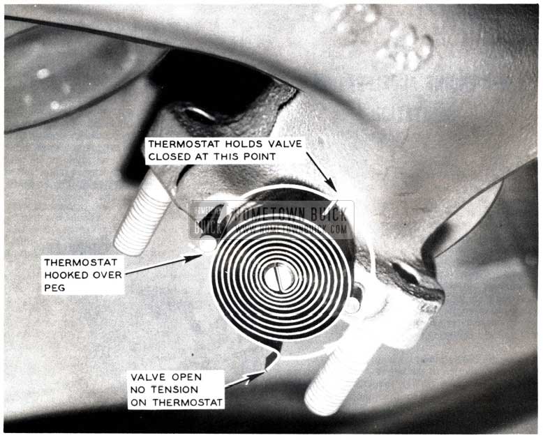
If after a complete tune-up, the hesitation condition still exists, a check of the V-8 engine’s manifold heat control valve should be made to be sure that the exhaust manifold thermostat is operating freely, and that the thermostat itself has been properly installed on the exhaust manifold. A quick check for proper installation is if, when the engine is cold, the valve’s counterweight is in an up position. (See Figure 21).
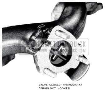
1953 Buick Exhaust Manifold Valve Spring not Hooked
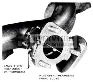
If the valve is binding or the thermostat is improperly installed, the counterweight will be hanging down (See Figure 20).
1953 Buick Exhaust Manifold Valve Spring
1953 Buick Exhaust Manifold Valve Spring Hooked
Some cases have been reported where the counterweight of the heat valve is binding against the starter motor splash pan. This can be remedied by reshaping the splash pan to allow clearance for the counterweight. In other cases the thermostat coil itself was improperly installed. This condition occurs when the thermostat spring is put on backwards or hooked up to the wrong peg. If either of these two conditions exist, improper thermostat action will follow with subsequent hesitating engine performance due to lack of heat in the intake manifold chambers.
If hesitation is still present after the aforementioned procedures and adjustments have been made, a change in the manifold heat control can be made to increase the intake manifold temperature. This added heat will provide better carburetion on cold engines and aid in smooth acceleration performance.
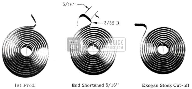
The free end of thermostat (Group 3.640, No. 1343657) is moved 25 degrees to increase tension (See Figure 24).
1953 Buick Exhaust Thermostat Coil
This change was started in production with engine No. V15828. All thermostats now available for service are of the new type.
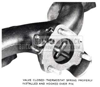
As illustrated in Figure 24, the thermostat can be reworked by shortening its coil 5/16″. Replace the reworked thermostat exactly as shown in Figure 23.
1953 Buick Exhaust Thermostat
If the rework is properly done, the thermostat spring tension should be sufficient to close the exhaust manifold valve at the point indicated in Figure 23.
If hesitation still exists, a rework of the intake manifold exhaust or heat holes in the intake manifold gasket Group 3.270, No. 1343631 may be done. This rework constitutes re-drilling the 1/2” heat holes to 5/8″. This change was effective in production with engine No. V14 764. All gaskets now supplied to the field will have the 5/8″ holes. These heat holes may be reworked by drilling, etc., but new gasket installation is more advisable and economical.
The above corrections are not to be campaigned and should not be performed except in cases where a complete tune-up does not eliminate the cold hesitation.
EXHAUST MANIFOLD BOLT LOCKING PLATE
SERIES 50 and 70
The Engineering Department has experienced some breakage of exhaust manifolds on the new V-8 engines. This condition is usually caused by excessive torque of the exhaust manifold bolts. Because of this torque, the exhaust manifolds cannot expand or contract as needed.
An exhaust manifold bolt locking plate (see Figures 25- A & B) has been designed which will properly hold the exhaust bolts when torqued from 10 to 15 ft. lbs. instead of 25-30 ft. lbs. as previously specified.
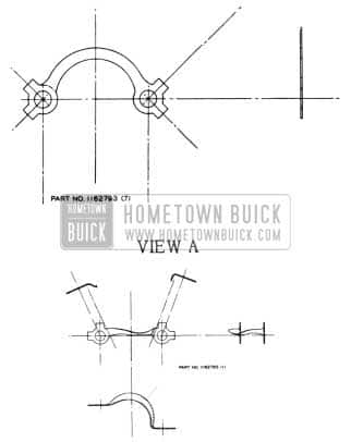
1953 Buick Exhaust Manifold Bolt Locking Plate
This lower torqueing of the exhaust manifold bolts combined with the slotted bolt holes in the manifold allows the exhaust manifold a slight movement on the cylinder head which compensates for temperature expansion and contraction.
One locking plate will lock two exhaust manifold bolts (Figure is, View A). Figure 25, View B is the locking plate used on the right front exhaust manifold bolts holding the generator support plate. In installation of this locking plate it is necessary to remove the generator. In all installations it is necessary to bend only one of the two tabs against the hex of a bolt head.
It is felt that all new V-8 Buicks should be equipped with these new exhaust manifold locking plates. This correction should be made at some time when other service to the car is necessary.
Flat rate for installation of locking plate: EXHAUST MANIFOLD BOLT LOCKING PLATES INSTALLATION INCLUDES:
R & R generator and bracket- torque manifold bolts from 10 to 15ft. lbs.
1953 (50, 70) 1.1 hr. (If equipped with power steering, add .1 hour.)
The locking plate is ordered under Group 3.604, No. 1162793 (7 required), and No. 1162795(1 required).
STROMBERG CARBURETOR REWORK
ALL 1953 STROMBERGS
Some carburetor difficulty has been reported on 1953 four and two barrel Stromberg carburetors. This has consisted mainly of stalling and a flatness condition.
In order to overcome these difficulties, some dealers have installed new carburetors after having unsuccessfully tried to correct the trouble. Carburetors received at the factory have, in most instances, been corrected by following the overhaul procedure given in .the 1953 Shop Manual (Section 3-G, Page 104).
Many of these carburetors could have been corrected if original adjustments and settings had not been disturbed and the specific difficulty, such as dirt or foreign matter had been removed or if idle and throttle and dash pot settings had been properly made or if modifications as outlined in previous BPS Bulletins had been accurately followed.
Float level adjustments are found off specification in most carburetors returned. Due to variations in the weight of floats and differences in gasoline pressures, float settings must sometimes be changed from the measured settings given in the Shop Manual. It is most important that the fuel level be at the bottom of the sight plug hole when viewed with the eyes level with the bottom of the hole. The car must be on a level floor with the engine idling. Care should be taken to see that floats are parallel and as nearly level with the cover as possible when the needle valves are seated and that there is no float interference with the sides of the float chambers.
Cold idle cam settings are found improperly adjusted in many instances. This is an important setting in that it controls the engine operation during the warm up period. On both Stromberg four and two barrel carburetors the throttle adjusting screw should rest on the second step of the cold idle cam, from the extreme cold position of the cam, when the choke valve is held against a No. 41 drill placed between the upper edge of the choke valve and the wall of the air horn. Adjustments, if necessary, should be made by bending the choke to cold idle cam rod to shorten or lengthen it, making sure that rod ends are not bent out of their right angle position. It is also important that the start aid lever and choke unloader adjustments be properly made as shown in Fig. 3-85 Page 122 of the 1953 Buick Shop Manual.
To correct flatness on 1953 Series 50 two barrel Strombergs, remove the standard .049 main metering jets and install .051 main metering jets group 3.754 part no. 1346707 after making sure the carburetor is otherwise set to specifications and that the engine is properly tuned.
VACUUM SPARK ADVANCE
Some of the 1953 Series 50 and 70 engines detonate very heavily for a short time interval as the throttle is changed suddenly from a part throttle at road load position to a wide open position (full acceleration).
This can be due to the time required for the vacuum advance unit to retard when the manifold vacuum drops.
Spark rap of this type can be greatly decreased by increasing the size of the vacuum spark advance take-off in the carburetor from the production drill size of .040 in. diameter to .081 in. diameter (No. 46 drill).
Production cars having carburetors built after May 1, Carter Code No. 2053S (Series 70) – No. 2017S (Series 50) Tag Date E3 or subsequent letter, and Stromberg Code, (Series 50)7-95A;(Series 70)7-94B will have an .081 vacuum spark advance take-off hole drilled as a factory specification.
The procedure for enlarging the port is listed as follows:
PRELIMINARY STEPS- ALL SERIES ENGINES
- Remove carburetor from engine.
- Remove throttle body from Stromberg Series 70, four barrel carburetor, only.
It is recommended that the above steps be taken to insure that the vacuum spark advance hole be drilled out on the same or nearly the same centerline as the original hole.
Before drilling, make sure the throttle valves are in a wide open position and protected with a piece of material to prevent damage from the drill.
Also, chips must be thoroughly removed from the drilled hole exercising a great amount of caution that no high pressure air be imposed upon the assembled carburetor. A blast of high pressure air on an external vent could collapse the floats.
In figures 26, 27, 28 & 29 the throttle bodies were removed from the carburetors for illustration purposes, with the exception of the Stromberg, four barrel carburetor throttle body which must be removed for the drilling operation.
50 SERIES STROMBERG
- Remove spark fitting from throttle body.
- Enlarge spark hole with No. 47 drill as shown in Figure 26.
1953 Buick Stromberg Throttle Body
It is recommended that when the preceding operation is completed, the “Automatic Choke and Fast Idle Cam Change” and “Surge Correction” operations be followed and completed as given on the following pages of this Edition.
- Reinstall carburetor on engine.
70 SERIES STROMBERG
- Turn idle speed adjustment screw counter clockwise until primary throttle valves seat tightly in bores.
- Using a No. 50 long shank drill, enlarge spark hole as shown in Figure 27.
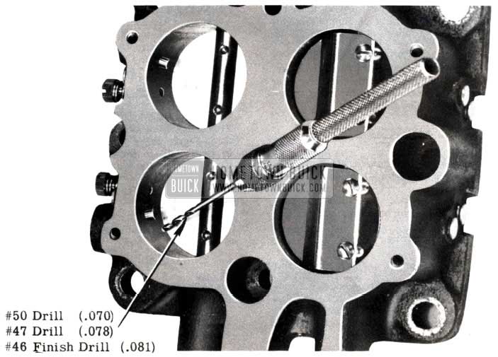
1953 Buick Stromberg Roadmaster Series Throttle Body
It is recommended that when the preceding operation is completed, the “Automatic Choke and Fast Idle Cam Change” operation be followed and completed as given in this Edition.
- Reinstall carburetor on engine.
- Warm up engine and set hot idle speed at 450 R.P.M.
FLAT RATE
Carburetor – R & R and adjust .7 hr.
Combinations:
1953 V-8 engine Stromberg Carburetor Complete Rework (Includes “Vacuum Drilling,” “Automatic Choke Settings,” and “Surge Correction,” Series 50; and “Vacuum Drilling,” and “Automatic Choke Settings,” Series 70.) .5 hr.
50 SERIES CARTER
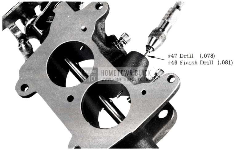
- Remove spark fitting from throttle body.
- Enlarge spark hole with No. 47 drill as shown in Figure 28.
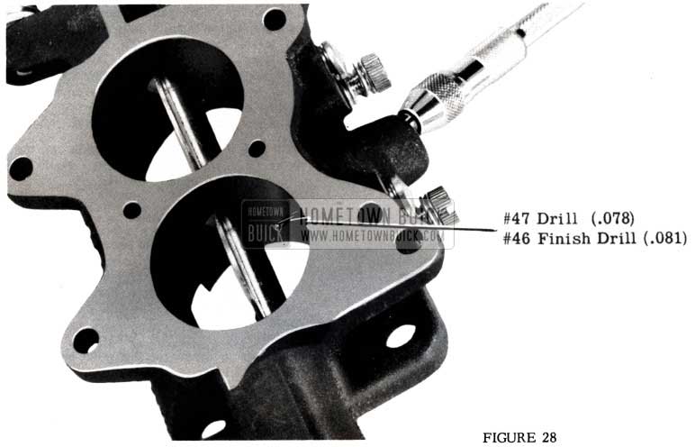
1953 Buick Carter Super Series Throttle Body
70 SERIES CARTER
- Remove spark fitting from throttle body.
- Enlarge spark hole with No. 47 drill. See Figure 29.
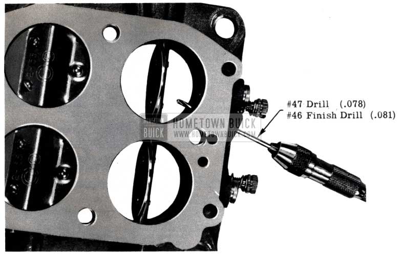
1953 Buick Carter Roadmaster Series Throttle Body
FLAT RATE
Carburetor – R & R and adjust .7hr.
1953 Series 50, 2 barrel Carter .2hr.
1953 Series 70, 4 barrel Carter .2hr.
AUTOMATIC CHOKE & FAST IDLE CAM CHANGE
STROMBERG CARBURETOR
To eliminate engine stall and improve warm-up characteristics of the Stromberg automatic choke, it is recommended that the following changes be made:
50 SERIES 1953 MODELS (CARBURETOR CODE NO. 7-95)
- Choke heat hole enlarged from a No. 56 drilled hole to No. 54 drilled hole.
- Rotate fast idle cam as per following instructions:
Procedure for making above change –
- Remove float chamber cover and air horn from main body.
- Remove float assembly (to avoid damage).
- Remove thermostat cover.
- Remove lead ball in horizontal vacuum passage of choke housing.(See Figure30-A)
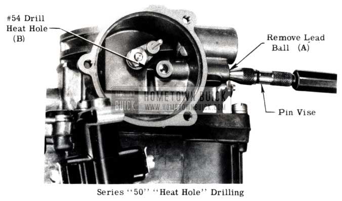
1953 Buick Carburetor Choke Housing
ROTATING FAST IDLE CAM “50” SERIES
- With a No. 41 drill between the upper lip of the choke valve and the air horn entrance, the throttle stop screw should come to rest on the short step of the fast idle cam with the choke rod in the lower end of the slot in the fast idle cam. See Figure 31-A.
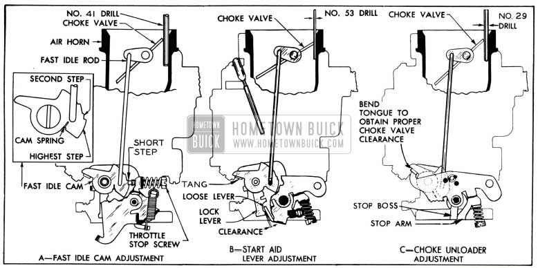
1953 Buick Carburetor Adjustments
To obtain this desired setting, bend the fast idle rod at the upper end with caution being taken that no binding exists at the point where the choke rod fastens into the choke stem lever.
Following the rotating of the fast idle cam the “start aid and choke deloader should be adjusted and checked as follows:-
“START AID”
- With a No. 53 drill held between the choke valve and the wall of the air horn there should be just enough clearance to allow the loose lever on the throttle stem to pass clear of the lock lever behind the fast idle cam. Figure 31-B.
- To obtain clearance at this point bend tang of lock out lever.
“DELOADER”
- The deloader should be adjusted so as to open the choke valve equivalent to a No. 29 drill when the throttle is opened to a wide open position. (See Figure 31-C)
- To obtain this adjustment place a No. 29 drill between choke valve and air horn.
- Bend tongue of the throttle lever to obtain correct opening.
- Close choke and also throttle. Now open throttle to a wide open position taking note if deloader opens choke valve, working through tension of loose lever spring.
70 SERIES 1953 MODELS (CARBURETOR CODE NO. 7-94A)
- Choke heat hole enlarged from a No. 60 drilled hole to No. 55 drilled hole.
- 70 hole drilled in head of choke vacuum piston.
- Rotate fast idle cam as per following instructions:
Procedure for making above change:
- Remove float chamber cover and air horn from main body.
- Remove float assemblies (to avoid damage).
- Remove thermostat cover. (See Figure 32-A)
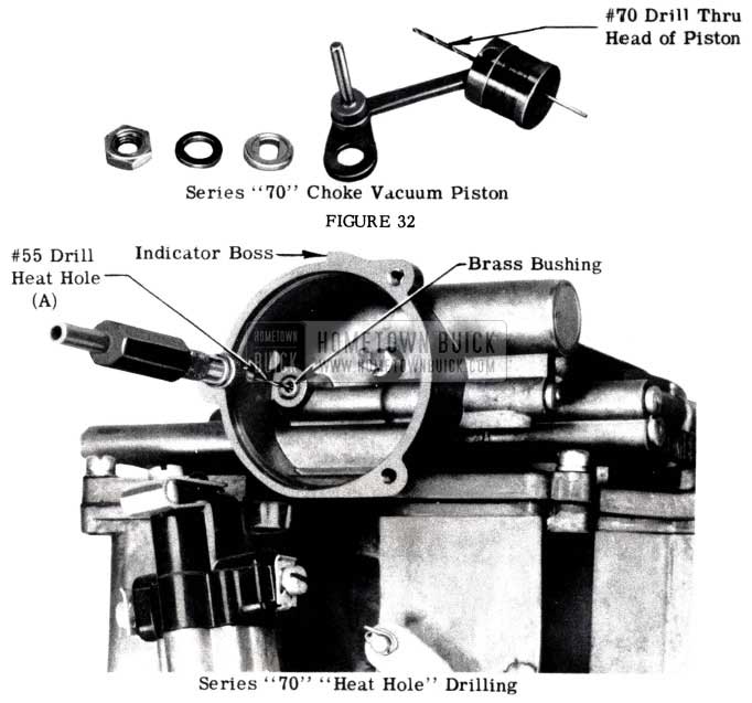
1953 Buick Carburetor Brass Bushing
ROTATING FAST IDLE CAM “70” SERIES
- With a No. 41 drill between the upper lip of the choke valve and wall of air horn entrance the throttle stop screw should come to rest on the short step of the fast idle cam with the choke rod in the lower end of the slot in the fast idle cam.(See Figure 34-A)
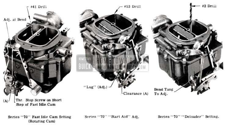
1953 Buick Adjusting the Carburetor
Following the rotating of the fast idle cam the “Start Aid” and “Deloader” should be adjusted and checked as follows:
“START AID”
- With a No. 53 drill held between the choke valve and the wall of the air horn there should be just enough clearance to allow the loose lever on the throttle stem to pass clear of the lock lever behind the fast idle cam. Figure 35-A.
- To obtain clearance at this point bend “lug” on lock lever.
“DELOADER”
- The “Deloader” should be adjusted so as to open the choke valve equivalent to a No. 2 drill when the throttle is opened to a wide open position. (See Figure 36)
- To obtain this adjustment place a No. 2 drill between choke valve and air horn bending tang of lock out lever.
- Close choke and also throttle. Now open throttle to a wide open position taking note if deloader opens choke valve working through tension of loose lever spring.
CARBURETOR SURGE CORRECTION
SERIES 50 STROMBERG CARBURETORS
Under some driving conditions it is possible to lower the fuel level in the float chamber of the Stromberg carburetor, Code No. 7-95, when making a right or left-hand turn thus causing a surging condition.
If complaints of this nature are received it is suggested to make the following change in the carburetor main body to eliminate the surge.
Recommended change –
Drill a 3/16″ hole through the wall of the baffle approximately 1 1/4” from the top of the casting as shown in Figure 39-B.
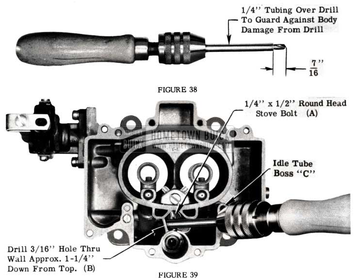
1953 Buick Carburetor Holes
Procedure for making correction-
- Remove air horn and float chamber cover from main body. Care should be taken so as not to damage float assembly.
- Remove throttle body from main body.
- Remove by-pass valve and gasket from main body. (See Figure 37-A)
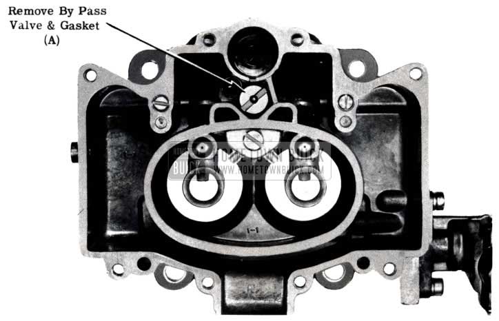
1953 Buick Remove Carburetor By Pass Valve and Gasket
NEW CARTER CARBURETOR
SERIES 70 ONLY
To improve the idle and slow speed performance of the Roadmaster engine, Carter has redesigned their Series 70, 4 barrel carburetor. The new carburetor is identified as the WCFB 2053 S and has many identifying characteristics when compared with the earlier or first type WCFB 996 S carburetor. Following are the new calibrations for the WCFB 2053-S.
1953 Buick Carter Carburetor – Roadmaster Series
1953 Buick Carter Carburetor Specifications – Roadmaster Series
FUEL GAUGE UNITS
ALL SERIES
An examination of gasoline gauge dash units (Gr. 3.108 No. 1517876 and 1517854) and tank units (Gr. 3.107, No. 1517475 and 1517200) which have been replaced and returned as defective or inoperative, has shown that many of these units function properly. In order to eliminate this condition, the test procedures outlined in paragraph 10-65 of the 1952 Buick Shop Manual should be followed. The AC Gas Gauge Tester Type No. 1 referred to in the Shop Manual is available from all AC Parts Distributors. The replacement of good parts is a waste of time and material and is unnecessary. All units returned for credit that are checked and found satisfactory by the factory will be returned to the dealer and credit refused.
Extensive tests on these returned gauges and dash units have proven that up to 80% are all right and are operating normally. We suggest that personnel contacting owners who are complaining about their fuel gauge operation point out the following: Fuel gauges are not finely calibrated instruments and are relied on mainly to indicate when it’s time to purchase more gasoline.
The construction of Buick gas gauges and tanks is such that after the gas tank has been completely filled there is a period of driving, sometimes as much as 100 miles, before the tank gas gauge float is no longer covered with gas and is able to float freely. Once this float can move, the dash unit will react to the amount of gas in the tank and register accordingly. The lower the fuel in the tank, the greater the accuracy of the gas gauge.
Therefore, Buick gas gauges may have a tendency to indicate an apparent greater amount of gas consumption from full to one-quarter (1/4) full than when the tank is completely filled or near the empty mark.
If this condition is called to your attention by an owner, it should be explained to him rather than attempt to repair by installing another unit.
GAS LINE CAMPAIGN
1953 SERIES 50-70
Recent reports have shown where the front end of the Series 50 and 70 rear gas line has been rubbing on the right front tire on sharp right turns. In these cases, the gas line is coming out of the clips used to secure it to the front fender skirt or it is not holding it close enough to avoid interference with the tire. This condition is often aggravated by the presence of ice, which forms on the gas line in winter conditions and with its added weight pulls the gas line from its fender skirt clips. The sagging gas line also causes the flexible hose connecting the gas line to the fuel pump to strike and rub against the front shock absorber. This condition, plus engine movement, is liable to wear a hole through the hose and subsequently cause a loss of gas.
It was decided to campaign the replacement of the old clip using the new clip, No. 1163294.
Secure the new clips with a No. 10 or No. 12 bolt with nut and lock washer. Rebend the gas line so that the flexible hose will lie in front of the shock absorber. CAUTION: Make sure the hose does not kink and stop the flow of gasoline. (See Figure40)
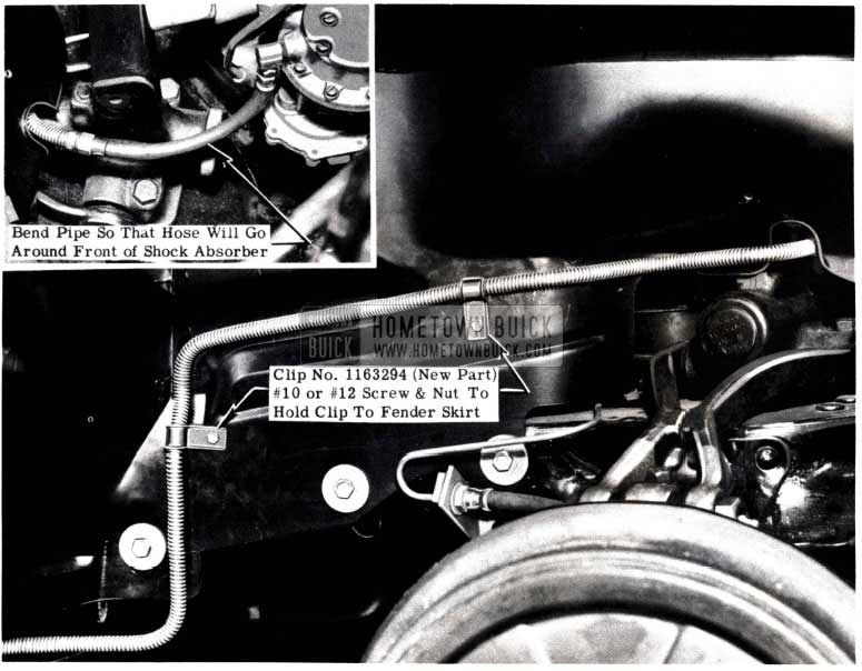
1953 Buick Gas Line
It may be necessary to tum the “L” fitting in the pump slightly forward to allow the flexible hose to lie in front of the shock absorber. Should this be necessary, care must be taken to provide proper hose clearance to the fan belt.
Time and material for this campaign may be submitted on AFA’s. An allowance of .6 hr. for labor is permitted. More than one car may be covered by an AFA providing all serial numbers are shown.
The new gasoline line clips will be available for service on or about April 1, 1953. Orders for them should be held until this time.
THROTTLE CROSS-SHAFT PULLOUT
ALL 1953 SERIES 50 & 70
Due to engine and chassis movement, it is possible, in some cases, to have the throttle cross-shaft drop out of the inboard bearing due to lack of adequate shaft protrusion. (See Fig. 41)
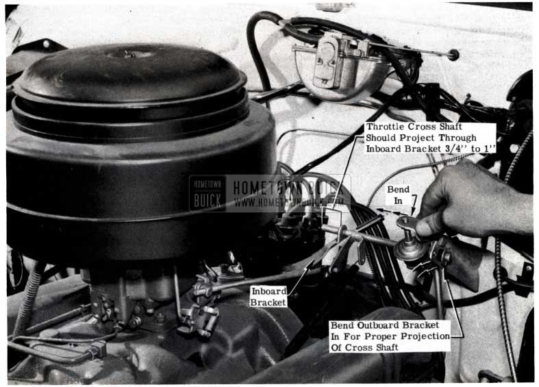
1953 Buick Throttle Cross Shaft
It is most important that this cross-shaft have the proper protrusion through the inboard bearing, (approximately 3/4” to 1″) to alleviate the possibility of this accurring as described above. It is recommended that all Buick V-8 engines be checked and those found having 1/2″ or less cross-shaft protrusion through the inboard bearing be corrected. This is easily done by merely bending the outboard bracket back to its normal position. (See Fig.41) It is important that this matter be given prompt attention.
CONTINUED THROTTLE CROSS-SHAFT PULLOUT
ALL 1953 SERIES 50 & 70
In the previous article, we stressed the importance of checking the throttle cross-shaft projection through the inboard bracket on all V-8 engines. As illustrated in Figure 41, this cross-shaft projection should be at least 3/4″ to 1″.
Some reports have stated that where this correction had been made, the cross-shaft continued to come out of the inboard bearing. Further checking revealed that the left engine mount (on steering wheel side) was not properly fastened to the mounting pad on the frame, thereby, permitting excessive engine movement.
It is felt, therefore, that if a throttle cross-shaft should come out after being properly positioned as per instructions in the previous article, and immediate check should be made of the engine mounts to be sure they are properly secured.
THROTTLE LINKAGE CORRECTION
There have been reports of hard accelerator action, because of improper adjustment, stiffness, bind, or alignment. Classification of these conditions are as follows:
- Stiffness:
Usually the stiffness or resistance pressure can be corrected by lubrication of all linkage brackets and rods at their pivot points. Production has now started a lubriplate operation to the throttle linkage and the above correction should only apply to early production cars. - Bind:
A bind can be caused by either a floor mat friction or a wedging action of the insulation. Bind can also be caused by the pedal itself when the fabric is broken at the hinge. To check, the pedal should be removed. The pedal base should then be held firmly to a flat surface with one hand and the flex action checked with the other hand by depressing the pedal and noting the return action. If only a slow or partial return is noted or if there is excessive side twist possible at the hinge point, a new pedal should be installed. Pedal attaching screws must be very tight to eliminate any shifting of the pedal. - Adjustment:
Check vertical throttle rod adjustment. There should be .040″ between the rear leg of the bottom bell-crank and the front face of the stop lug on the mounting bracket when the throttle is closed and in hot idle position, otherwise the idle adjustment on the carburetor will be ineffective.
With engine shut off, adjust horizontal throttle rod so it unloads the automatic choke when the accelerator pedal is fully depressed. This adjustment cannot be made until the floor mat is installed, as the mat acts as the pedal stop, rather than having the stop on the throttle lever strike hard against the boss on the throttle body. (If any difficulty is encountered in making this adjustment check length of throttle rod. Series 50 rod is 10 1/8″ overall, Series 70 rod is 10 7/8″. It is possible to put a Series 50 rod on a Series 70 engine.
The best adjustment of the dash pot can be made as follows: With the engine hot, back the dash pot off until it is ineffective, then screw down until it touches the throttle lever when engine is idling. Set the brake firmly, put transmission in “Drive” range, speed the engine up to about 1400 rpm and snap the throttle shut. If engine stalls, move the dash pot down until its action prevents the engine from stalling, then lock it in position with the jam nut.
Leave A Comment
You must be logged in to post a comment.