1953 Buick Battery Shield
BATTERY SHIELD & HOSE CLIP CAMPAIGN
SERIES 50-70
The following is a copy of “Special Service Letter – Dealer No. 123”.
In order to eliminate the possibility of the Dynaflow transmission cooler hose and car heater hose from coming in contact with the left exhaust manifold of the 1953 Buick V-8 Engine, the following correction is being made. This revision is now incorporated in the present production built cars.
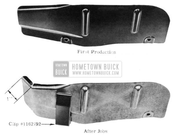
- Remove battery shield No. 1318922 from right rear lower comer of battery box.
- By use of a three cornered file or hack saw, place a small notch in upper lip of shield approximately 1″ from rear edge. (See Fig. 1)
- Place shield in vise at notched 1″ point and bend this section away from the engine at approximately a 40 degree angle, or until cover follows contour of battery box base.
- Reinstall shield front mounting bolt loosely.
- Reinstall shield rear mounting bolt and add hose clip, Group 9.787, Part No. 1162792, (Fig. 1)
- Tighten both shield mounting bolts to 5 ft. lbs. torque.
- Place transmission and heater hose inside clip.
In order to eliminate the possibility of hose failure, it is suggested that all cars previously built be reworked as stated in this bulletin.
This change was effective with the various Serial Numbers as follows:
Atlanta 66808210
Framingham Start of 1953
Linden Start of 1953
South Gate 26769006
Kansas City 46787744
Wilmington 56801226
Flint 16746318
All cars prior to above Serial Numbers should be campaigned and have this change made on them. AFA’s for material and .3 of an hour labor may be submitted. More than one car may be listed on an AFA providing all Serial Numbers are given.
SERVICE CONNECTING RODS
1951 SERIES 40 – 50
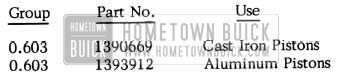
Sales figures still indicate that dealers are not using proper connecting rods in servicing rebuilt engines.
When cast iron pistons were originally used in 1951 Series 40 and 50 engines, the material specifications of the connecting rods and rod caps were changed to compensate for the increased piston weight. In order to eliminate the possibility of the incorrect rods being used, it was decided to stock only the strengthened type for all service replacements. The original rod assemblies, for use with aluminum pistons, are again available and will be supplied in addition to the cast iron style. Extreme care must be exercised to ensure that the correct rods are used in engines having cast iron pistons.
Correct connecting rod ordering information for 1951 Series 40 and 50 jobs is as follows:
1952 Buick Service Connecting Rods Parts
V-8 ENGINE CONNECTING ROD REPLACEMENTS
1953 SERIES 50 & 70
In conjunction with the current V-8 engine piston ring campaign, we find that many connecting rod bearings are being replaced unnecessarily. Examination of returned bearings indicates that at least 90% were suitable for use and need not have been replaced. We cannot condemn anyone for being cautious and keeping the best interest of our owners in mind; however, a great number of connecting rod bearings which have been replaced because of discoloration or minor scratches in the center of the bearing could have been put back in the engine. Also, some cases have been noted where the insert has a groove in the center that matches up with the oil hole in the crankshaft. This is caused by a burr on the crankshaft at the oil hole. These inserts are perfectly all right to use in the engine.
With the types of motor oils now being used, bearings as well as other engine parts are bound to become discolored in a rather short time. The discoloration has nothing to do with their ability to do the job nor their overall operating life. This applies to small scratches in the center portions of the bearing as well.
Please caution all personnel in this regard and make every effort to eliminate this waste of valuable parts.
V 8 ENGINE HARMONIC BALANCER
1953 Series 50 & 70
Upon full acceleration from a speed of 55 to 65 MPH, as when passing on a highway, a sudden, slight roar or “whoom” may be heard on some of the 1953, 50 & 70 V-8 jobs. This noise will last only through a 3 or 4 MPH cycle between the above mentioned speeds. The above speed range is due to the different rear axle ratios used, tires, etc. There is no noticeable vibration accompanying this condition. If vibration is present, something other or more than Torsional Vibration is concerned.
To overcome this condition of crankshaft torsional vibration, all V-8 engines, as listed below, will be equipped with the new Harmonic Balancer.
1953
Series 50 – Dynaflow & Power Steering V 1465195 continuous
Series 50 – Dynaflow V 1350145 through V 1382995 starting again with V 1418395 continuous
Series 50 – Synchromesh V 1349905 through V 1382995 starting again with V 1418395 continuous
Series 70 – V 1465017 continuous
At present there are no numbers available for when the above change will affect Air Conditioned jobs. When this information is available it will be issued in a future BPS.
The new V-8 engine Harmonic Balancer will be available to the field. It is cautioned however, that the use of this balancer is only for the conditions described above. It will not aid engine balance if other units are unbalanced or causing vibration, nor will it help any conditions occurring in other speed ranges. It is suggested that if there is any question on whether the: noise is Torsional Vibration, and if there is any vibration present, reference should be made to the engine balancing procedure as outlined on Page 40, Paragraph 2-13 of the 1952 Buick Shop Manual or on Page 173 of this BPS subject “Body Noises.”
The Parts Department will service the following parts of the New V-8 Harmonic Balancer.
0.659 -1318810- Balancer- Harmonic
0.659 -1318811- Pulley- Fan Driving
0.660-1318819- Spacer- Pulley
For Service these parts will be used as follows: On 1953-50 (For one groove)
Use 1-0.659 -1318810- Balancer- Harmonic
On 1953-50 with Power Steering or Air Conditioning and on 1953-70 (For 2 grooves)
Use 1-0.659 -1318810- Balancer- Harmonic
1-0.659 -1318811 -Pulley- Fan Driving
1-0.660 – 1318819 -Spacer- Pulley
3-NGN-NPN-Bolt-Hex Hd
5/16-18 X 13/8
3-8.931-120638- Washer- Lock 5/16
On 1953-50 with Power Steering and Air Conditioning and on 1953-70 with Air conditioning (For 3 grooves)
Use 1-0.659 -1318810- Balancer- Harmonic
2-0.659 – 1318811 -Pulley – Fan Driving
2-0.660 – 1318819 -Space –Pulley
3-NGN-NPN -Bolt-HexHd-5/16-18 X 2
3-8.931-120638- Washer- Lock 5/16
HYDRAULIC VALVE LIFTERS
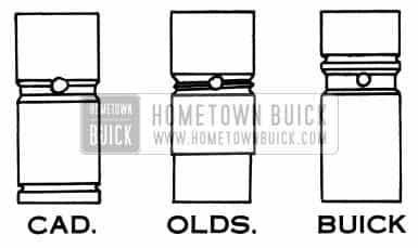
The question has arisen as to whether Cadillac or Oldsmobile hydraulic valve lifters could be used in the new Buick V-8 engines. Although the lifters are dimensionally suitable, both Oldsmobile and Cadillac lifters are made from a material which is not compatible with the steel camshaft used in Buicks. The use of these lifters would result in very early engine failure due to lifter and camshaft failure.
1953 Buick Hydraulic Valve Lifters
Figure 2 illustrates the difference between the three types of lifters.
V-8 ENGINE OIL CONSUMPTION
SPECIAL SERVICE LETTER -DEALER NO. 126
A few cases of excessive oil consumption (more than one quart per 500 miles after 3,000 or 4,000 miles) have been reported on 1953 V-8 engines.
- In these cases the engine should first be carefully checked for exterior oil leaks. Naturally, any leaks found should be corrected.
- Because of smooth bore finish and the type of rings used in production combined with low speed short trip type operation, it is possible that some rings may not seat for 3,000 to 4,000 miles. Normally, this type bore finish and ring set up is conductive to long ring life.
- Each job should be carefully checked and a record kept to accurately determine the amount of oil being consumed in each job.
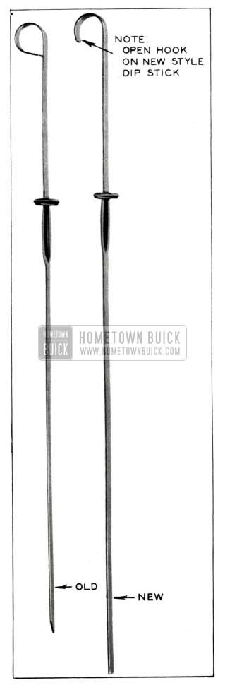
- It has been called to our attention that in many cases inaccuracies are being caused by service station attendants in reading engine oil gauge rods (dipsticks). Apparently the situation is most prevalent on Buick’s new V-8 engine. As near as we can tell, there are three reasons for this:
- The attendant bends the dipstick upon removal or replacement so that the end of the stick does not pass through the hole in the crankcase baffle. In this case the stick slides across the baffle and under the crankshaft. When it is removed for reading it is dry and both the attendant and owner think the crankcase is empty.
- Our present dipsticks do not extend to the bottom of the pan and it is possible to obtain a dry dipstick reading and still have from 3 to 3 1/2 quarts of oil in the pan.
- The dipstick is calibrated with full and low level lines. It requires 2 quarts of oil to bring the oil level up from the low to the full marker.
In many cases the oil level is being checked too soon after stopping the engine so that oil in the overhead system has not had sufficient time to drain back into the crankcase. At least 3 or 4 minutes should be allowed for drain back.
Any of the above, or any combination of these conditions can lead to excessive overfilling of the crankcase. We have had numerous reports of 12 to 13 quarts being drained from a crankcase. Needless to say, this represents waste and unnecessary expense to the owner.
It is therefore our recommendation that a dipstick check of the level be made after adding two quarts of oil, if the dipstick showed empty or was dry when the initial check was made. If this is done, an intermediate reading will be obtained which will indicate how much more oil is actually necessary to obtain the proper level.
The oil gauge rod currently used, Group 1.516, Part 1343634 is being replaced in production by a longer, stiffer rod. (See Figure 3)
1953 Buick Oil Gauge Rod
For these reasons, all first type oil gauge rods are to be replaced by the new type, Group 1.516, Part ll63538 which will be available from the Buick Parts Warehouses approximately April 15th. AFA’s will be accepted for the oil gauge rods and more than one serial number can be listed on one AFA.
- If after all checks are made and the car has been drive 3,000 to 4,000 miles and excessive consumption is still evident, it will be necessary to put in a new set of rings. Our Parts Department has presently available, on a car tie-up basis only, a replacement ring set package, Group 0.643, Part 1391624 that contains a new type oil control ring. The replacement type oil control ring is the double steel rail type with separator and expander. The steel rails and separator are temporarily cemented together for ease of installation. In use, the cement is quickly dissipated and the rails and separator work independently. (See Figure 4)
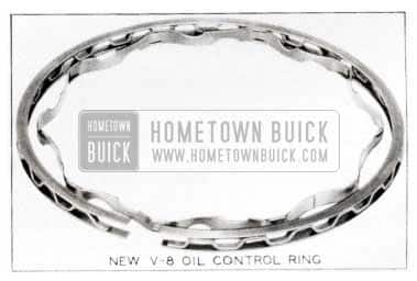
1953 Buick Oil Ring
Also, experience with this type oil control ring in V-8 Engines has shown the need for locating the ring gap on the high side of the cylinder. This is accomplished by placing the ring gap in line with the valve head recesses on the piston top. Piston installation procedure remains the same.
ENGINE OIL IN COOLING SYSTEM
1953 SERIES 50-70
If oil is found mixed with the engine coolant in some of the 1953 Series 50 and 70 radiators, it should first be determined whether this oil is from the Dynaflow cooler unit or engine. If there is doubt as to which unit is leaking, the use of the oil dye as described on Page 1 of this Abridged Edition is suggested.
In an attempt to alleviate needless replacement of parts, the following procedure has been set up to test the V-8 engine cylinder heads for oil leaks. If the cylinder heads prove to be all right and do not leak, it will then be necessary to replace the engine block.
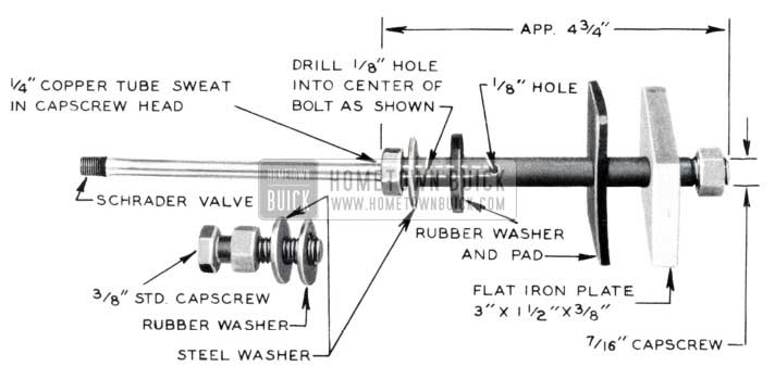
1953 Buick Engine Oil in Cooling System
Figure 5 illustrates the equipment recommended to make this cylinder head oil leak test. As shown, a 7/16″ x 4 3/4″ capscrew is used. A 1/8″ hole is drilled down through the center of the capscrew approximately 1 1/2″ deep. Another 1/8″ hole is then drilled through the side of the bolt toward the bolt center connecting with the previously drilled passage. (See Figure 5) Drill the head of the capscrew with a 1/4″ drill deep enough to allow installation of a 1/4″ copper tube. Before installing the copper tube into the capscrew head, a standard Schrader type valve should be secured to one end of it. (See Figure 5) However, any means whereby air pressure can be applied to the tube is suitable.
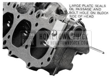
Install testing unit in the front cylinder head bolt hole with the drilled oil passage and tighten securely. (See Figures 6 & 7)
1953 Buick Engine Case Capscrews
1953 Buick Cylinder Heads
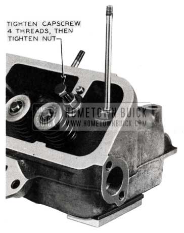
A 3/8″ standard capscrew of any length may be used to plug the overhead rocker arm oil inlet passage. (Set-up as shown in Figure 5)Tum the capscrew into the cylinder head about 3 or 4 threads and tighten nut. (See Figure 6)
Immerse entire cylinder head in water and move head around slightly to be sure that all air pockets have been eliminated. It is suggested that if possible the head be held at a slight angle in the water (not lying flat on bottom of water tank) so that if there is a leak and air does escape, the bubbles can escape to the surface of the tank where they can be seen.
Apply 70-80 lbs. air pressure to the tester and check for small bubbles.
It is necessary to check both ends of the V-8 cylinder heads; therefore, after following above procedure, install testing equipment in opposite end of head and repeat check, as outlined above. When checking this rear passage it will be necessary to remove the welsh plug (Gr. 0.034 No. 1343096) on the rear end of the cylinder head, to enable you to see any air bubbles which may be escaping.
BENT OIL GAUGE RODS
1953, SERIES 50-70
There are some cases where the oil gauge rod has been bent when it was reinstalled in a new V-8 engine after an oil check. This condition is usually caused by a careless insertion in which the oil gauge rod catches on the edge of the crankshaft oil baffle and is deflected. When this occurs the oil gauge rod, instead of going through its opening and down into the lower crankcase pan, slides along on top of the crankshaft oil baffle (See Figure 8).
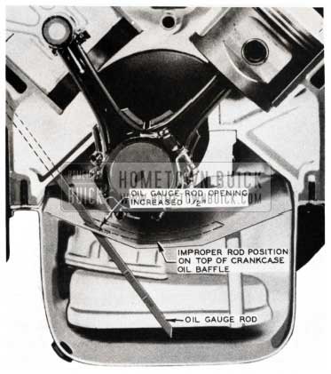
1953 Buick Crankshaft Oil Baffle
When this situation occurs, two very serious conditions may result:
- The oil gauge rod, laying on top of the crankshaft oil baffle, is in close contact with one of the counterweights or throws off the crankshaft. The oil gauge rod may become entangled with the crankshaft and be damaged.
- As illustrated in Figure 8, the dip stick does not enter the lower crankcase area and therefore on oil level inspection, the oil gauge rod will appear dry indicating an empty crankcase. Overfilling of the crankcase may result.
Production has increased the oil gauge rod opening in the crankcase oil baffle another W’ to eliminate the danger of striking it when inserting the oil gauge rod.
It is suggested for those V-8’s now in service to rework the oil gauge rod to eliminate the above described conditions:
Secure the oil gauge rod in a vice approximately 1″ above the full line. (See Figure 9).
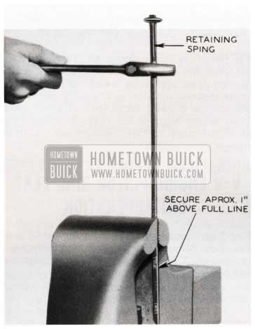
1953 Buick Oil Gauge Full Line
Clamp a wrench or vice grip pliers directly below the retaining spring on top of the oil gauge (See Figure 9). Twist the wrench 360 degrees or completely around once. (See Figure 10).
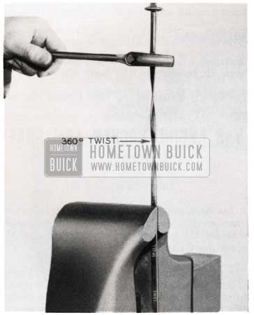
1953 Buick Twisted Oil Gauge
This twist in the oil gauge rod will tend to make the rod rigid and less easy to bend.
Special notice should be given to Service Department personnel to check and, if necessary, rework as described above, all oil gauge rods whenever servicing any V-8 engines.
OIL FILTER LEAKAGE
SERIES 50 & 70
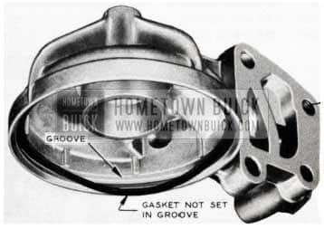
It has been brought to our attention that in some cases oil leakage is being experienced after replacement of an oil filter cartridge. This oil leak is usually caused by a dislodged and improperly fitted gasket and/or allowing the filter can to turn as it is being tightened. Either or both of these conditions will result in the cutting of the oil filter can gasket and cause an oil leak.
1953 Buick Oil Filter
Figure 11 illustrates an improperly fitted gasket. The valve assembly has a grooved recess that provides for the gasket and insures proper seating. Care should be exercised when installing the gasket to insure its proper seating.
After the gasket is properly installed and the oil filter can bolt is securely started, the can should be held from turning while the bolt is secured. The holding of the filter can will eliminate cutting of the gasket by the turning edge of the filter.
V-8 PISTON FITTING
SERIES 50-70
Because of the 45 degree angle of the cylinder on the new V-8 engines, a method different than that used on the straight-eight engine is required for service fitting of pistons to cylinder bores.
The following method has been tested and is suggested for use in service fitting pistons:
Follow the instructions on “Inspection of Cylinder Bores, Pistons, and Rings as directed in sections b and c, pages 2-39, and 2-40 of the 1952 Buick Shop Manual. In section don page 2-40, follow the “Reboring of Cylinders and Fitting of New Pistons” instructions through to one paragraph above the Clearance Limits data. When working on the V-8 engine in the chassis, the following instructions should be used:
Wipe piston and cylinder bore clean and dry. Make sure that the ribbon (W’ x 1r x .003″) of Feeler and Scale J 5540 is free of dents or burrs, then place it on the lower side of bore, at a point 90 degrees to the normal piston pin location. Install piston in bore with head downward and piston pin in its normal position parallel to the crankshaft. (See Figure 12).
1953 Buick Piston Fitting
Hold the piston and slow1y pull the scale in a straight line with the ribbon, noting the pull required to move the feeler ribbon at a steady speed. The pull will be between 7 and 13 pounds if the piston has the required clearance of .0007″ to .0017″.
The rest of the instructions given in the Shop Manual after the above identified stopping place (in Section d) are applicable to the V-8 engine if it is being repaired while on an adjustable engine stand wherein the cylinder barrel could be positioned at a 90 degree angle to the floor. This would then allow the piston to “fall” straight down as in the straight eight engine.
V-8 ENGINE PISTON RING FLAT RATE OPERATION
Flat Rate operations taken from the 1953 Chassis Flat Rate Manual for V-8 piston ring operation to be used on A.F.A.’s in the current campaign is as follows:
Operation 6-17 Engine Inspection – 7.5 hrs.
Operation 6-17-11 Rings R&R (Includes check fit) – 1.4 hrs.
Operation 6-17-12 Minor Engine Tune-up – 1.5 hrs.
Total time for operation is 10.4 hours.
Add if necessary the following:
Operation 6-17-6 Cylinders (all) remove glaze 1.2 hours. (If necessary to R&R hood, add .6 hr.)
The effective date of the 1953 Chassis Flat Rate Manual was August 17, 1953.
V-8 ENGINE ROCKER ARM SHAFT BRACKET BOLTS
1953 SERIES 50 & 70
It has been called to our attention that in several cases service men have tightened the rocker arm shaft bracket bolts too tight when performing service operations on the V-8 engine.
The specified torque for these bolts is 30-35 ft. lbs. If they are pulled down tighter than this it is possible to crack the rocker arm shaft bracket. A crack in this bracket will cause excess oil to flow over the cylinder head and valve stems. As you can readily see, this could very well result in excessive oil consumption.
It is also felt that the cases of bent push rods and valve stems encountered in the field are caused by tightening the rocker arm bracket bolts faster than the engine oil can leak past the valve lifter plunger.
lf the rocker arm bracket bolts are pulled down too fast, the lifters will offer momentary resistance through the push rods to the brackets causing the described condition.
It is recommended that all personnel, especially those concerned with this type of engine service operation be cautioned regarding this matter.
REPLACEMENT ENGINE NUMBERING
STRAIGHT-8
In the past, Service Replacement Engines had the R. E. engine number stamped just above the Engine Numbering Pad on the right side of the crankcase. This location has now been changed, and the R. E. engine number will be stamped on the Right Engine Support Mounting Pad on the side of the crankcase. This applies to all Service Replacement Engines which receive an R. E. number.
ENGINE SPARK RAP
19S3 SERIES 50-70
Some complaints of spark rap during light and medium throttle accelerations have been received concerning 19S3 Series 50 and 70 cars.
This type of detonation can be reduced and m most cases eliminated by installing a 3/8″ long spacer between the vacuum advance unit spring and the spring retaining nut on the distributor. See Fig.13.
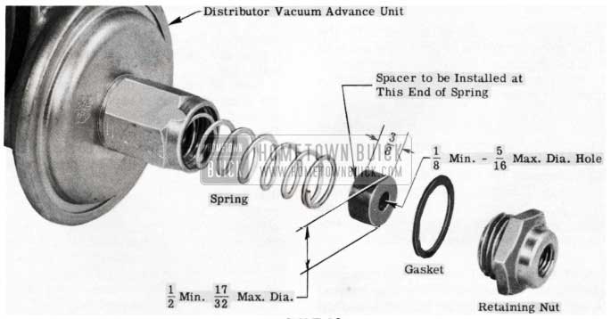
1953 Buick Distributor Vacuum Advance Unit
This spacer must be 1/2 to 17/32 inches in diameter and must have at least a 1 /8″ diameter hole through the center. A piece of pipe of 1/4″ inside diameter may be used. Copper tubing is not recommended due to the thin wall not making a suitable seat for the spring.
Care must be taken when removing and installing the spring retaining nut that the vacuum advance unit housing is not rotated. Two wrenches, one to hold the hex on the housing and one to turn the nut must be used to avoid damaging advance unit. Check ignition timing after installing the spacer in the vacuum advance unit.
This distributor modification will not help full throttle detonation which is usually due to carbon accumulation or low octane gasoline.
See Page 79 of this ED.” Distributor Modifications.”
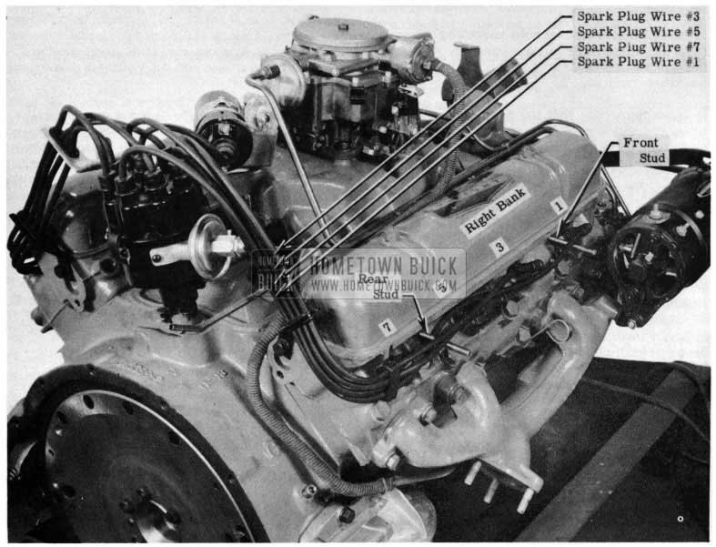
SPARK PLUG WIRING
19S3 SERIES 50 & 70
Due to the fact that No. 3 and No. 1 cylinders fire consecutively on the right bank of the 19S3 Series SO and 70 V-8 engines, and No. 4 and No. 8 on the left bank, it is being drawn to your attention that these wires must not be adjacent to each other in the grommets, otherwise, cross-firing may result, and can be a contributing factor in burning holes in pistons. It may also have other adverse effects on engine operation such as to cause engine missing and short spark plug life.
On all 19S3 Series SO and 70 cars, the ignition wires must be checked and, if necessary, regrouped as indicated in Figures 14 & 15.
1953 Buick Spark Plug Wires
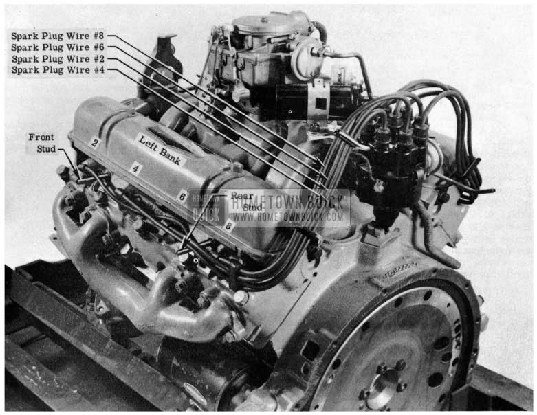
1953 Buick Spark Plug Wiring
No. 3 spark plug wire must be located in the top hole of the grommet at rear of spark plug cover as well as in the grommet located in the rear support bracket. No. 1 spark plug wire must be located in the bottom hole in both grommets.
In addition, No. 1 plug wire is to be assembled over the top of forward spark plug cover stud, then passed below No. 3 spark plug, then over No. 5 plug and underneath the rear spark plug cover stud and No. 7 plug. This will prevent No. 1and No. 3 plug wires from lying parallel and also prevents No. 1 wire from being inadvertently pinched underneath the spark plug cover during assembly.
Figure 15, of Left Bank. No. 4 spark plug wire must be located in the bottom holes in both grommets. No. 8 spark plug wire must be located in the top hole of both grommets. No. 2 spark plug wire is to be assembled over top of front cover stud, then underneath No. 4 spark plug, then over top of No. 6 plug and underneath rear cover stud and No. 8 spark plug.
It must be cautioned that damage will be done to the spark plug rubber caps if a timing light clip is fastened to the spark plug through the rubber cap.
Due to the high frequency of the 12 volt system, great care must be exercised not to rupture or puncture any of the high tension ignition cables. When a timing light is to be used, it is suggested that a distributor cap wire protecting rubber nipple be pulled up the spark plug wire and a thin screwdriver or wire be inserted alongside of the spark plug wire into the distributor cap. A timing light clip may then be attached to the extended metal screwdriver or wire. CAUTION: Tum off engine when inserting wire or screwdriver into the distributor spark plug wire lead-in.
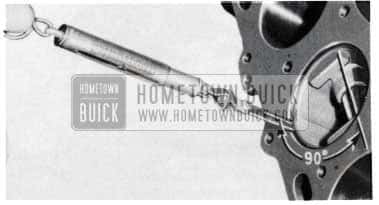
FLYWHEEL TIMING MARK CHECK
1953 SERIES 50-70
There have been requests from the field for a simple method of checking the location of the timing mark on the flywheel in conditions where the mark has become obscure or question as to its proper position is raised.
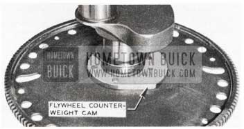
1953 Buick Flywheel Counterweight Cam
Figure16 is a general view of a flywheel and crankshaft. Observe the flywheel counterweight cam.
In checking the timing mark, cycle the engine until the flywheel counterweight cam is parallel with the bottom of the engine and pointing toward the starter motor side of the engine. (See Figure 17)
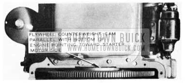
1953 Buick Flywheel Counterweight Cam – Side View
Observe the primary pump converter cover to flywheel bolt, (NOTE: The bolt has been removed for illustration purposes) the only one visible if flywheel is in proper position (See Figure 18).
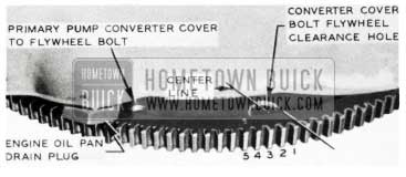
1953 Buick Flywheel Bolt
When looking at the flywheel while facing rear of car, observe the first converter cover bolt flywheel clearance hole to the right of the primary pump converter cover to flywheel bolt (See Figure 18). Draw an imaginary line through the center of clearance hole to the center of flywheel gear as illustrated and count back or left 5 teeth. The fifth tooth is the correct timing mark tooth and should be identified by yellow paint and a “5” stamped on its side.
CORRECT ENGINE TIMING
1953 SERIES 50 & 70
The following method is suggested to quickly check the position of the timing gears in relation to the timing chain on the new Buick V-8 engines.
With the timing chain cover removed, the chain and gears will appear as shown in Figure19, except for the variable position of the gears and copper washers.
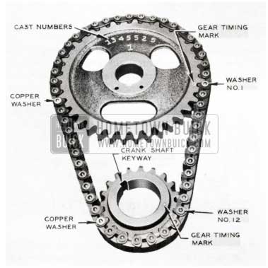
1953 Buick Engine Timing Chain
Because of the crankshaft and camshaft gear ratio, the copper washers on the timing chain used to set up the initial timing of these gears, will come into position next to the gear timing marks (See Figure 16) only once every 51 engine revolutions. Therefore, in order to eliminate excessive cycling of the engine, position just the two gears as shown in Figure 19. Do not loosen or remove drive gears from shafts. The lower crankshaft gear key-way can be observed and should be placed as shown in Figure 19in relation to the upper or camshaft gear. The camshaft gear position can be set by the timing mark and cast number as shown in Figure 19.There should be 12 washers between the two gear timing marks. If there are 12 washers as illustrated in Figure 19, then the gears are in their proper timing relationships.
VIBRATION
1953 ALL SERIES
There have been some reports of a vibration condition in some 1953 cars. Our experience indicates this condition can be caused by one or a combination of the following:
- Out of balance wheels and tires
- Front hub and brake drum assembly
- Rear drum and axle shaft assembly
- Out of balance propeller shaft
- Engine and transmission.
The method for testing and checking out the above items is outlined below. In testing the car on the road the car should be driven by a competent inspector who can, to a degree, determine from experience what is causing the trouble. The following paragraphs are to aid in diagnosing the trouble.
- Wheels and tires, if not properly balanced, etc., will be detected at lower speed, sometimes as low as 15 MPH coming in more or less as roughness and with increased speed, develop into up and down shake, wheel tramp, road noise, rumble in cars, etc.
- Unbalanced front hub and brake drum assembly and rear drum and axle shaft assembly will act same as wheel and tire and should be corrected for balance, prior to wheel and tire balancing.
- Propeller shafts that are out of balance will usually be noticed at higher speeds and will cause vibration in body floor board. This can be detected at approximately 65 MPH and gets worse as speed is increased. It is very seldom that you can pull through this type of vibration. If there is any question in deciding on this vibration, the vibration will become more noticeable with added passenger loads.
- Engine and transmission vibration can sometimes be detected without car being in motion and if it is thought a period is detected at for example, 30 MPH it will recur at 60 MPH or double the engine speed. (It is advisable to use a tachometer for checking engine vibrations.)
Procedure for correcting above items:
- Refer to 1952 Shop Manual, Page 276, Section 6-24. Rough, yet balanced tires should be checked by inflating all tires to 60 pounds to see if trouble is eliminated. If it is, lower pressure in tires one at a time until the trouble shows up again. This will reveal the offending tire.
NOTE: Excessive runout of wheel and tire will effect a wheel and tire vibration. With a critical case the runout should be held to a minimum of 1/8″; 1/16″ would be desirable.
In using a balancing machine that balances wheels and tires on cars, it generally is not necessary to balance the hub and drum and drum and shaft assembly. However, in critical cases it may be necessary to balance hub and drum and drum and axle shaft assemblies before balancing wheels and tires on car. If wheels and tires are removed and balanced off car, then it will be necessary to check balance of hub and drum and drum and axle shaft assemblies.
- A satisfactory way of checking and balancing front hub and drum is to mount on a knuckle spindle with clean front wheel bearings. (Do not adjust bearings too tight.) Add weight as necessary to bring into static balance.
Drum and axle shaft can be static balanced by mounting in lathe centers adding weight as necessary. (Do not pinch centers too tight and lubricate centers or use ball bearing centers.)
- Rear Axle Propeller Shaft.
The Service Department has no way of checking or correcting propeller shafts for balance. However, if it is determined that the vibration is being caused by the shaft, remove the complete propeller shaft assembly and check for straightness as outlined in 1952 Shop Manual, Section 5-17, Page 247.
It has been our experience that if the shaft is straight it will be in fairly good balance.
An out of balance condition of this type can also be caused by an improperly fitted torque ball and if it is thought that this is a source of trouble, check torque ball for fit. A loose or tight fitting torque ball will give an effect of an out-of-balance shaft.
- To correct engine and transmission balance, refer to this Abridged Edition, Page 173, subject “Body. Noises”, and Bulletins BPS 2.323, page 47 on 1951 and 1952 Series issued May 30, 1952, or Page 121 of 1951-52 BPS Abridged Edition with the following additional checks.
- Check runout of pulleys, radial and lateral. If runout exceeds .010″ replace with new pulleys.
- Check engine flywheel for runout. This must not exceed .007”. Correct if necessary.
- Check fan for balance. Correct if necessary.
NOTE: A satisfactory way to check this is to place fan on a close fitting arbor on two knife edged blocks. Remove metal from end of heavy blade or blades.
Also check fan blades for runout before removing from engine. Straighten blades if necessary so that they do not exceed 1/16″ runout.
SHOP MANUAL CORRECTION ON VALVE GUIDES
PAGE 36
Sub-paragraph D, Group 2-22, Page 36 of the 1953 Buick Shop Manual states as follows:
“Use Reamer J 129-3 to remove any burrs raised during installation of guides. Guides are finished reamed to provide proper clearance for inlet and exhaust valve stems.”
The preceding paragraph is in error and should be crossed out of the Shop Manual. The valve guides carried by the Parts Department for service are not finished reamed. This applies to the V-8 as well as the Straight 8 engine valve guides. After installing new guides, it will be necessary to finish ream them (Reamer J 129-3) in the head until proper valve stem fit is achieved.
CARBON BLASTING OR CLEANING
CAUTION: TOXIC DUST
It has been recognized that carbon deposits which accumulate in engines using leaded fuels contain toxic compounds.
Under certain conditions the dust from the removal of these deposits may be harmful to mechanics performing the operation. For this reason it is recommended that mechanics who are engaged in removing carbon deposits from engines by blasting, scraping, or with a power driven wire brush should wear an approved toxic dust respirator. The type of respirator used must be designed for protection against the inhalation of toxic dust. Your State Health Department can supply you with a list of approved respirators for this purpose.
Operations involving the removal of carbon deposits should always be performed in a well-ventilated area so that dust from these operations will not affect other personnel.
BUICK ENGINE ENAMEL & DECALS
ALL 1953 BUICK V-8 ENGINES
Recent inquires have been received regarding the identity and possible availability of the engine enamel that is used by the Buick factory on the V-8 engine.
Due to limited usage of this engine enamel, coupled with infrequent demand for it in the field, makes it inadvisable that either it or exact matches for it be established for distribution. For those rare occasions where the engine block may require overall refinishing, (after complete removal of grease and other foreign matter has been accomplished), the recommendation of a close match in an already available “Dulux” color should prove entirely satisfactory. The following active “Dulux” colors are offered as being relatively close matches to the current factory finishes:
Buick V-8 Motor:
93-71782 Tahoe Green
93-2908 Narva Green
93-55911 Lakewood Green
93-57287 Fernmist Green
Occasionally there are requests for the Straight 8 and V-8 engine rocker arm cover decals. These decals are now available and may be ordered from:
Buick Parts & Accessory Merchandising Dept.
Buick Motor Division
Flint, Michigan
Leave A Comment
You must be logged in to post a comment.