12 V-BATTERY FREEZE UP
For record purposes, the following is a copy of a “Special Service Letter” No. 122 sent to the field.
There have been recent reports of 12V batteries freezing while cars are in storage. This freezing is caused by a low charged condition.
The specific gravity of all 12V batteries in inventory or in cars must be checked with a hydrometer. All batteries found with a specific gravity of 1.220, which is the absolute safe minimum, or below, when corrected to 80 degrees Fahrenheit, must be recharged. Specific gravity at time of delivery, wherever possible, should not be less than 1.250 at 80 degrees Fahrenheit. A fully charged 6 or 12V battery has a specific gravity of 1.260 to 1.280 at 80 degrees. Corrections for temperature in order to arrive at 80 degrees can be made by adding .004, usually referred to as 4 “points of gravity”, to the hydrometer reading for every 10degrees Fahrenheit that the battery electrolyte is above 80 degrees Fahrenheit, or subtract 4 for every 10 degrees Fahrenheit the battery electrolyte is below 80degrees Fahrenheit (Refer to 1952 Shop Manual, Fig. 10-4, Page 1 0-14 for chart).
Model 3EE 70 12V batteries may be checked for state-of-charge by means of the same hydrometers and open circuit cell voltage meters now used in checking the 6V batteries.
Standard hydrometer floats usually are not calibrated below 1.160 and therefore, cannot show the condition of 12V batteries in a very low state-of-charge. For this reason, as much as 40 ampere hours of recharging may be necessary on a completely discharged Model 3EE70 12V battery before the electrolyte supports the float and allows readings to be taken .
All testers of the open circuit voltage meter type, in order to be reliable, must either be based on a full charge specific gravity of 1.270 or used with a correction factor of .01 Volt/10 points in specific gravity.
Example – A battery that has a specific gravity of:
1.270 and reads 2.13V across each cell is 100% charged.
1.260 and reads 2.12V across each cell is 90-95% charged.
Because of an increase in the cranking motor ratio and less current draw, a 12V battery may start a 1953 V-8 engine even when in a dangerously low charged condition. In contrast, a 6 volt battery will not start the Straight Eight Engine when in this low state-of-charge and, therefore, gives warning of its “run down” condition. Due to this lost ”safety factor” care must be exercised in checking all 12V batteries in stored cars or stock to prevent freezing.
Following is a table of the freezing points of batteries in various state of charge.
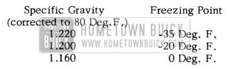
1953 Buick Battery Freezing Point
In charging batteries on a series charger, it is possible to charge 6 and 12V batteries together on the same series. This is possible as the 12V battery is, nothing more than two 6V batteries connected together, a condition duplicated on a series charger.
12-V BATTERY CORROSION
1953 SERIES 50 & 70
In some cases there has been excessive corrosion of the cell connectors, particularly at the positive end of the battery, on some Model 3EE70 batteries in 1953 Series 50 and 70 cars. This corrosion appears as a reddish-brown sludge on the exposed lead parts.
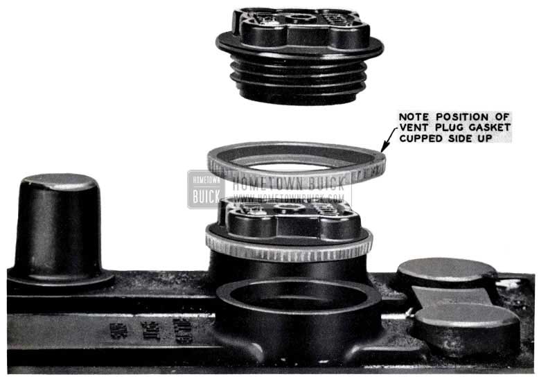
Corrosion of this kind results from a leakage of current to the grounded battery hold-down straps through a film of acid and road dust on top of the battery. Twelve volt batteries corrode more rapidly that six volt batteries because the higher voltage, and exposed connector straps, allow more current leakage. A film of acid may result from (1) loose or improperly installed gasket on vent plugs, (See Fig.87), (2) overfilling (refer to 1953 Shop Manual, Paragraph 10-15a), (3) overcharging, or (4) leaks in cell covers or sealing compound.
1953 Buick Battery Corrosion Repair
Correction:
Since corrosion occurs only where acid is present, it can be prevented by keeping the top of the battery clean and dry. Wash acid-soaked batteries and hold downs with a soda solution or dilute ammonia water. Rinse with clear water. Do not allow the cleaning solution to enter the battery cells. Be sure the hold down cover is properly centered and that the rubber spacers are properly installed in each corner. Check the vent plugs to make sure the baffles are in place and the yellow gaskets are installed properly. (Cupped side up, See Fig. 87)
After thoroughly cleaning and drying the connector straps and adjacent surfaces, coat the connectors with melted battery sealing compound, making certain that a good bond is obtained with the cell cover all around the connector. Battery sealing compound may be obtained from any battery service station.
NOTE: If washing reveals cracks or leaks in case, cover, or sealing compound, battery should be replaced, depending upon condition.
BATTERY “ACID PROOF” COATING
In the article above, subject “12- V Battery Corrosion” we outlined a procedure for correcting the 12-V battery connecting straps deterioration due to acid action on top of the battery. We have since received information from the Wyandotte Paint Products Company regarding a black acid proof coating available through them for the purpose described in the above identified BPS article. This material is available in either quarts (75 cents) or gallon ($2.00) containers and should be ordered under: “Black Acid Proof Coating” (code No. N4V 4971) from the Wyandotte Paint Products Company, Wyandotte, Michigan.
DISTRIBUTOR CENTRIFUGAL ADVANCE MODIFICATIONS
1953 50 & 70 SERIES
The 1953 V-8 engines may have a tendency to pre-ignite at high speeds. To alleviate this condition the centrifugal advance curve of the V-8 engine distributors have been modified for speeds above 4000 engine RPM. This modification will not cause a loss in performance or maximum car speed. The maximum advance limits for the new distributor is 24.7 degrees to 31 degrees engine degrees advance at 4000 engine RPM as compared with the previous production distributors maximum advance limits of 28 degrees to 36 degrees engine degrees advance at 4300 engine RPM.
This change went into effect on Distributor Number 1110827, (Service Part Number 1922284 Gr. 2 .361) having a code date of 3C28 or later. In the code date, the first number represents the year, the letter represents the month, A being January, B being February, etc. The letter “I” is omitted so the letter “J” represents September. The last number represents the day of the month. For example, 3C28, represents March 28, 1953, and 3M31 represents December 31, 1953
It is suggested that these changes be noted and checked against any present Spark Control Advance specifications. This may help eliminate confusion when checking a late production distributor for Maximum Spark Control Advance in Flywheel degrees.
It is not possible to convert any of the first production distributors to the new lower maximum spark advance. It is to be noted however, that the advance curves, vacuum, centrifugal, and their combination, remain the same for all the 1953 V-8 distributors up to the maximum as specified for each distributor.
These instructions were only for distributor vacuum advance unitsidentifiedbyNo.1116068. (See F. 88)
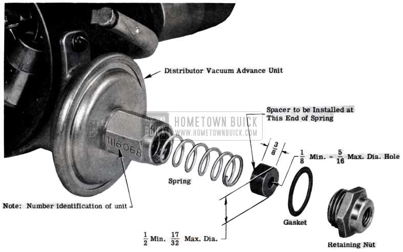
1953 Buick Vacuum Advance
DO NOT under any circumstances place the spacers in the distributor vacuum advance unit type No. 1116083.
BURNED DISTRIBUTOR ROTOR TIPS
1953 SERIES 50 & 70
If the tip of a distributor rotor on a 1953 Series 50 or 70 car is badly burned, the following check should be made for proper rotor alignment.
Place the distributor in a fixture and remove the cap, leaving the rotor installed. Rotate the shaft clockwise until the contact points just open to fire the number 1 cylinder. Place a straight edge on top of the rotor as shown in Fig.2. If the straight edge lines up with the primary terminal as shown in figure A, the distributor cam is defective and must be replaced. Figure 89 shows the proper rotor position when the number 1 cylinder is fired.
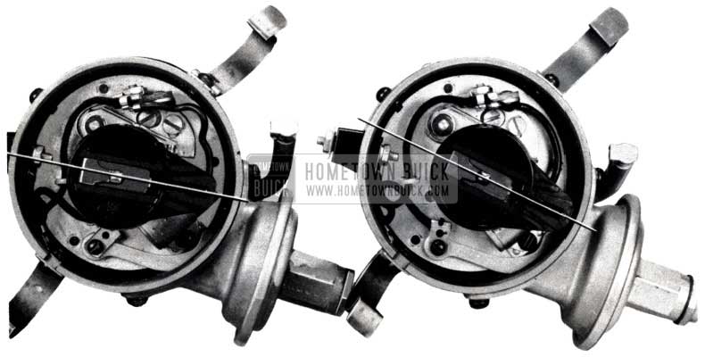
1953 Buick Burned Distributor Rotor Tips
Changing the rotor alone will not correct the trouble.
ARMATURE SHAFT DAMAGE
ALL SERIES
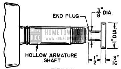
Field reports show that some armature damage has resulted from pounding on the drive end of hollow shafts during disassembly or assembly of the pulley or the drive end frame. Pounding can result in the following damage:
- Armature laminations may become loose on the shaft as the result of the sudden end thrust. This allows the laminations to shift endwise during rotation, damaging the insulation between the lamination and commutator. This will cause armature failure due to shorting between the leads. Also, shifting of the lamination will produce a vibration in the generator which eventually causes the leads to break.
- The end of the shaft may be expanded enough to prevent assembling the bearing or commutator end frame.
- The threads on the end of the shaft can be damaged, preventing assembly of the nut which holds the pulley in place.
- The shaft may be forced through the end of the commutator end frame and the bushing driven out of place.
- The ball bearing in the drive end may become brinelled or dented causing bearing failure.
Therefore, care must be taken when disassembling or assembling the generator to avoid pounding on the end of the shaft. Always use a gear puller to remove the pulley or the end frame. To prevent damage to the shaft when using a puller, insert a plug in the end of the shaft. A plug as shown in Fig. 90, or some other suitable plug may be used.
1953 Buick Armature Shaft Damage
OPERATION FOR UNDERHOOD TESTS
1953 SERIES 50 & 70 – 12V SYSTEMS
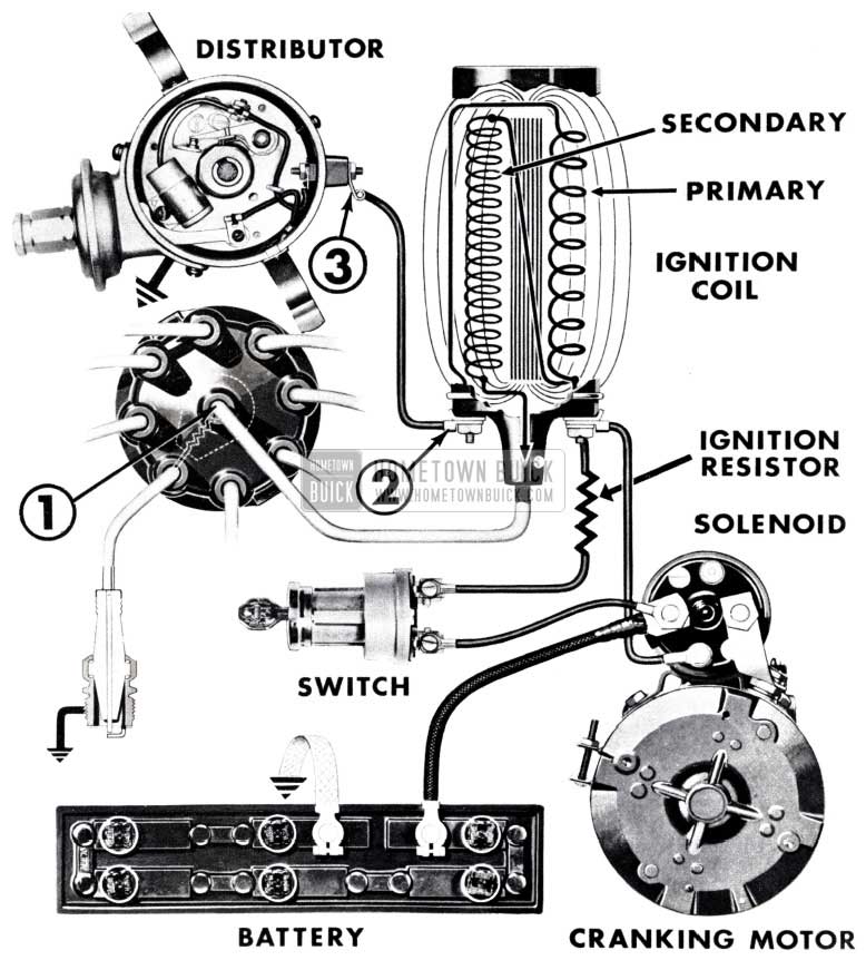
The cranking circuit of the new 12-volt system for the new Buick has a unique feature which makes it necessary to change certain service test procedures. As can be noted in Figure 91, the cranking circuit in the 12-volt system for passenger cars contains a by-pass lead that connects the battery directly to the ignition coil during cranking.
1953 Buick Cranking Motor Operation
This lead completes the ignition circuit so that current flows directly to the ignition coil without passing through either the ignition switch or the neutral safety switch. The purpose of the bypass circuit is to obtain improved starting performance at low temperatures by bypassing the ignition coil resistor. This special circuit it completed through a contact finger located in the cranking motor solenoid and is energized by the contact disc of the switch as the main contacts close. During cranking the by-pass circuit carries full battery voltage to the ignition coil and the engine can fire even though the regular ignition switch is “off” and the shift lever is in a neutral safety position. Therefore, care must be taken to break the ignition circuit before operating the cranking motor from the engine compartment with any type of temporary starting switch. To do this, (1) pull the secondary lead out of the distributor (See No. 1 of Fig. 91) and ground the lead, or (2) disconnect the end of the primary lead at the ignition coil (See No.2 of Fig.91) or (3) disconnect and tape the end of the primary lead at the distributor to prevent grounding (See No. 3 of Fig.91). Anyone of the above methods of breaking the ignition circuit or the method suggested on this page, shown below, will prevent the engine from firing, but if considerable cranking is done as in checking engine compression, method (2) or (3) should be used in order to protect the contact points from the higher primary current.
REMOTE CONTROL STARTER SWITCH
IMPORTANT CAUTION ALL V-8 MODELS
All Service Department personnel should be cautioned regarding the use of a remote control starter switch such as Kent – Moore Tool No. J 2679 on cars equipped with the new V-8 engine. If installation of such a switch is made in the usual manner, as is done for positioning the flywheel, and for other service operations, it is possible for the engine to start and run as long as the button is pressed regardless of the position of the shift lever. To avoid the possibility of this happening it is necessary to install a jumper wire from the low current (primary) post of the distributor to ground. This is the only recommended method, although we know there are others. Extensive, long period use of even this method may result in damage to the coil.
Please be sure that this information is understood by everyone in your organization.
SOLENOID STARTER MOTOR SWITCH FAILURE
1953 SERIES 50 & 70
Reports reveal occasional cases of solenoid switch trouble on 12-volt starter motors which may be caused by improper assembly of the switch.
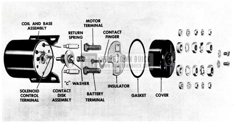
Solenoid switches giving trouble have been found to have the return spring out of place. (With the cover in position, the spring should rest in the recess of the “C” washer at one end and in the cover boss at the other.) (See Fig. 92)
1953 Buick Selenoid Starter Motor – Exploded View
This misplacement has resulted in the following conditions:
- Intermittent running of the cranking motor armature while engine is operating. (This is caused by the unsupported contact disk drifting into the main switch terminals.)
- Engine stops running. (This is caused by the misplaced return spring grounding the ignition coil terminal inside the switch.)
- Complete switch failure. (Switches have been found in which the unloaded “C” washer has slipped out of the groove in the contact shaft resulting in disassembly of the contact parts.)
When trouble occurs, as described above, the starter solenoid should be detached from the motor and the terminal cover and plunger removed. (It is necessary to remove only the mounting screws and the nuts from the MOTOR and SOLENOID CONTROL terminals in order to detach the cover. Do not break welded connections.) If the contact parts are undamaged, reassemble them correctly, following the order shown in Fig. 92. This can be done readily if the solenoid is placed vertically on the bench with the terminals up. Place the contact disk assembly in position with the return spring in the recess of the “C” washer. Lower the cover into place taking care that the spring does not fall over. Holding the cover in place with one hand, reach into the barrel of the solenoid and push on the end of the contact assembly shaft with any suitable rod or tool to check for return spring action. If spring action is satisfactory assemble the cover permanently; if not, remove the cover and check the assembly.
INCORRECT 12V IGNITION CONNECTION
1953 SERIES 50 & 70
To obtain greatly improved starting performance at low temperatures in the new 12-volt applications, a special circuit by-passes the ignition coil resistor and carries full battery voltage directly to the ignition coil during the cranking cycle. As the cranking cycle is completed, the special circuit is broken and the current is directed through the ignition coil resistor before entering the ignition coil.
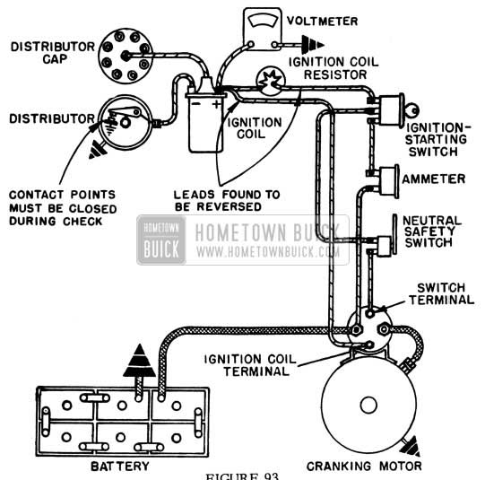
TROUBLE: Reports on 12-volt ignition system failures have shown that in some cases the leads attached to the positive terminal of the ignition coil and to terminal of the ignition coil resistor are reversed, either at the units or at some junction point in the circuit. (See Figure 93).
1953 Buick Starter Motor Test
Two damaging effects may be expected from these wrong connections:
- The ignition coil resistor is by-passed so that full battery voltage is applied directly to ignition coil when the engine is running. This results in almost immediate damage to the distributor contact points and makes it necessary to replace the contact points after only a few minutes of operation.
- Should the ignition switch be left in an “on” position for any length of time with the engine not running, serious damage to the ignition coil may result. Excessive heat produced by the increased flow of current damages the internal structure of the coil. Internal damage is indicated by a bulge in the bottom of the coil can.
TESTING TO DETERMINE CORRECT CONNECTIONS: To determine if leads are properly connected attach positive lead of voltmeter to the positive terminal of the ignition coil and ground the other voltmeter lead. With the ignition switch in an “on” position and with the distributor contact points closed, the voltmeter reading should be approximately 5 to 7 volts for a correct installation. If the leads are reversed, the voltmeter will indicate full battery voltage.
CORRECTION: If the voltmeter indicates full battery voltage, first check the leads connected to the junction block, if a junction block is in the circuit, to see that the ends of the clips from the terminals are not touching. If the voltmeter still reads full battery voltage, reverse the leads to the positive terminal of the coil and the lead at the terminal of the coil resistor. Check again with the voltmeter. The reading should be approximately 5 to 7 volts. If the voltage reading remains the same as full battery voltage, check the circuit.
Whenever wrong connections are found, always examine the bottom of the ignition coil can. A bulge denotes the ignition switch has remained in an “on” position for a period of time without the engine running, resulting in internal damage to the coil and the coil must be replaced. If the bottom of the can is not bulged, even though the ignition switch had remained ON, the ignition coil has not been damaged and replacement is not warranted.
NEW COIL RESISTER POSITION & WIRING HARNESS
1953 SERIES 50 & 70
During the later part of June, the Ignition Coil Resistance Unit was moved from next to the Ignition Coil to a new location on the fire wall. This move was to improve the location and reduce the fire hazard. This new location required the releasing of a new Chassis Wiring Harness due to the different length of leads. For service, the Parts Department will replace the 1st type Wiring Harness by the 2nd type which will require the installation of a 2nd type Resistance Unit when a new Wiring Harness is installed.
Following are the parts affected:
Group 2.555 – 5296944 – Harness-Chassis Wiring
1953-50-70 Dynaflow 1st-Jobs
To Be Replaced By:
Group 2.555 – 5299818 – Harness-Chassis Wiring
1953-50-70 Dynaflow After Jobs
When installing 5299818 on a 1st-Job car, it will be necessary to install one (1) Group 2.185-1927236 Resistance Unit.
Since the wire clip on the Resistance Unit was also changed at the same time, both the 1st and 2nd type Resistance Units will be serviced by the Parts Department.
CHANGE IN WIRING HARNESS WIRES BETWEEN COIL & STARTER MOTOR
ALL 1953 SERIES 50 & 70
In all early production “wiring diagrams” and previous articles on ignition connections, it was illustrated that two wires, one from the junction block and one from the ignition switch both connected to the positive side of the ignition coil.
Since our wiring harness change in production (Refer to the previous article) there is now only one wire on the positive side of the ignition coil. The new, or after production wiring harness still includes the cranking circuit which contains a by-pass lead that connects the battery directly to the ignition coil during cranking. This connection is now made in a splice in the wiring harness instead of at the coil connection.
Figure 94 is the corrected Series 50 and 70 wiring diagram. Note splice of wires 16 BNP and 14 RC just before ignition coil.
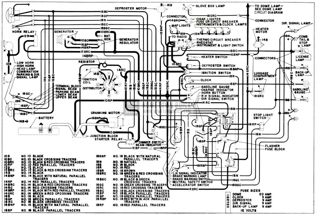
1953 Buick Starter Motor Wiring Diagram
NEUTRAL SAFETY & BACK-UP LIGHT SWITCH
SERIES 50-70
It has been found that a great number of the combination neutral safety and back-up light switches were improperly connected on cars built prior to Serial No. 16745216. These cars must be checked and reconnected if necessary in accordance with Figure 95.
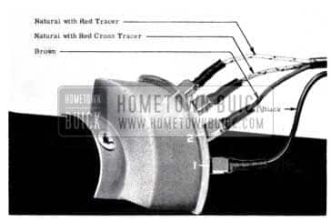
1953 Buick Back-Up Light Switch Wiring
The correct wiring as shown in Figure 95 when viewed from the driver’s seat is as follows:
Right Terminal No. 1 – Black wire
2nd from right No. 2 – Brown wire
3rd from right No. 3 – Natural with red cross tracer wire
Left hand terminal No. 4 – Natural with red parallel tracer wire
If switch is not wired correctly the engine may crank with shift lever in other than neutral or parked position, or starting motor may engage when shifting from low to drive during a heavy pull. Or, backup lights may operate with shift lever in a position other than reverse.
It has been found that the switch lever has broken in some instances. This has been due to improper forming of the control lever stop plate, located at the lower end of the steering column mast jacket, which permits the shift arm to ride over the top of the stop, thus the switch lever to act as the stop. Where this condition is found the shift control lever stop plate must be replaced if it cannot be adjusted to obtain the dimensions shown in Figure 96.
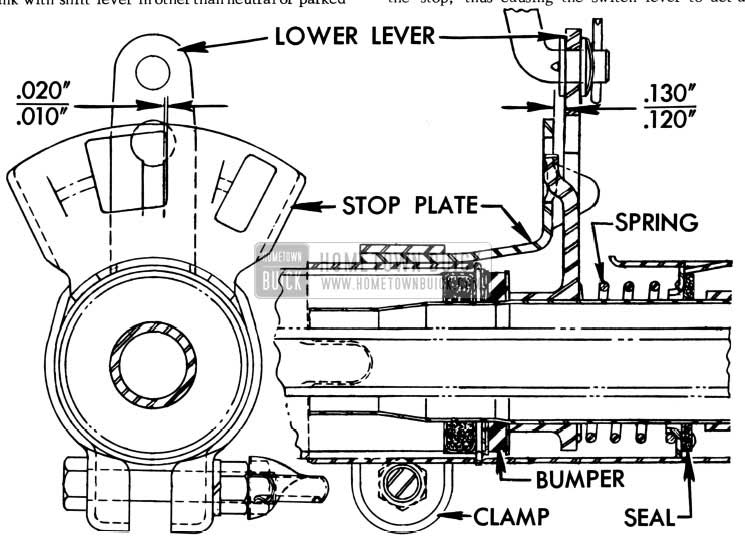
1953 Buick Neutral Safety Switch
With the control lever in the “Drive” position, a clearance of .120″ to .130″ (1/8″) must exist between the lower lever and stop plate. A clearance of .01 0″ to .020″ must also exist between the tongue on lever and the nearest edge of the large hole in stop plate. The stop plate may be adjusted as required after loosening the clamp bolt.
If the stop plate cannot be properly positioned to obtain these dimensions and function as it should, i.e., prevent over shifting, it will have to be replaced.
CAUTION: Excessive bending of the plate or detent may cause breakage.
Leave A Comment
You must be logged in to post a comment.