BRAKE CHANGES
Series 40
The 1953 Series 40 will have the same brake specifications and dimensions as the 1952 Series 40. However, all series are now equipped with the new orange-colored brake shoe lining. This lining was started in production on all late 1952 production. Tests have proven this lining to be the best available. All 1953 brake rebuild kits will have the new orange type lining.
Series 50
The 1953 Series 50 will now have 12 x 2front and rear brake shoes. The shoe lining, as in Series 50 front shoes are still interchangeable with earlier models through the 1940 Series 60. Due to the increase in size, the 195s3eries 50 rear brake shoe kit is interchangeable with earlier Series 70 models through l 941.
Series 70
The 1953 Series 70will have the same 12 x 2brake shoe as last year. However, Series 70 equipped with power brakes will have a high pressure type of lining which can be identified by its black-colored edge. The front brake shoes are not interchangeable with any Series 70 earlier than the late 1952 production change. The late 1952 cars equipped with the new type lining can be identified by the position of the anchor pin, which is 3/16 inches lower than that in the older models.
POWER BRAKES
SERIES 70 ONLY
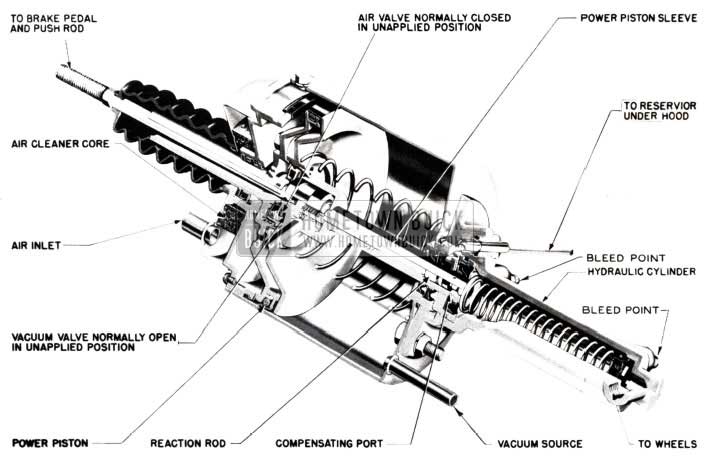
Buick’s new Power Brake Unit, optional on the Series 70 performs all the functions of a master cylinder, therefore eliminating the use of the conventional unit. The hydraulic fluid reservoir is mounted in a convenient location under the hood and is connected to the unit by means of a short length of 5/16″ tubing.
By taking advantage of the power supplied to the braking system by the Buick Power Brake Cylinder, the pedal ratio (leverage) is materially reduced enabling the reduction of the total brake pedal travel by one-half. In that the unapplied height of the brake pedal is now approximately the same height as the accelerator, this factor aids materially during a brake application in reducing both time and effort in braking. All that is required now in “right foot braking”, is to swing the toe to the left from the accelerator to the brake pedal pivoting on the heel. “Left foot” braking, that has recently become more popular, since the advent of the fully automatic transmission, has been rather a difficult operation. “Left foot” braking is now feasible through the use of the Buick Power Brake, because it gives the operator accurate complete control of his brakes along with both a reduction in pedal effort and pedal height.
The Buick Power Brake is a vacuum suspended type of brake power unit. By vacuum suspension is meant that normally with engine running, brakes unapplied, the full vacuum chamber of the unit, that is both sides of the power piston, are held at engine manifold vacuum. The brakes are applied merely by the admission of air to the cover side of the power piston, while the full manifold vacuum is maintained on the cylinder side of the power piston. This differential is pressure; atmosphere on one side and vacuum on the other, causes the power piston to move forward, thereby exerting a thrust on the small piston in the hydraulic cylinder which in tum increases the line pressure to the four wheels.
Therefore, it can be readily seen that since the vacuum chamber of the unit is already at manifold vacuum, before a brake application is made, no other separate vacuum tank or reservoir is required when the Buick Power Brake is used. Since a manifold check valve is installed in the vacuum source line, between the engine manifold and the unit, vacuum is maintained in the unit even if the engine should stall.
REMOVAL OF POWER BRAKE UNIT
- Remove pin from push rod and remove push rod.
- Remove air intake lines.
- Remove reservoir line and drain reservoir. (Do not re-use this fluid.)
- Remove cylinder to distributor high pressure brake line.
- Remove vacuum line at check valve.
- Remove securing nuts (4) from power cylinder.
REASSEMBLY
Reassembly procedure is a reverse of the removal procedure. Upon completion of step 2, check brake pedal grommet at dash. This accordion type grommet should be compressed 3/8″ when pedal is against the stop-bolt; if not adjustment should be made by loosening lock nut and turning pedal stop bolt until the required adjustment is made.
Refill reservoir with Delco No. 11 brake fluid. Adjust push rod so that a slight play or looseness is evident between pedal end and power cylinder. The brake pedal should have a slight clearance before it activates the power cylinder.
Loosen jam nut on rear of push rod. With jam nut loose, insert push rod into power cylinder. NOTE OF CAUTION: The power brake valve requires only 4 lbs. of pressure to actuate the control valve.
Great care must be exercised when installing the push rod into the valve body so as to lightly touch valve seat. Any pressure on the push rod will open the valve. The open valve will in turn build up pressure in the hydraulic system and will cause the brakes to lock after a few miles of driving.
Hold brake pedal tightly against pedal stop bolt. Brake pedal is now in the extreme released position. The push rod, inserted into the power cylinder, should be just touching the control valve. Adjust the length of the push rod until the clevis pin can be easily installed with finger pressure.
A shorter adjustment is safer as a long push rod will actuate the brake valve even with the brake pedal fully released.
There is no difference in settings or procedures. Brake shoe settings and procedures are the same for both manual and power brake jobs. These settings are the same as those used in previous years. However, in power brakes it is not possible to higher or lower pedal engagement by a brake adjustment. After properly setting brake shoes on a power brake job, the pedal will have a certain height and this cannot be adjusted up or down.
Normal pedal height from lower, back edge of pedal to floor mat is approximately 2 inches.
Bleeding the brake system is accomplished in a similar manner as that used to bleed conventional brake units. However, Buick’s Power Brake Unit has two bleed fittings on the power cylinder and both of these must be bled (See Figure 74).
1953 Buick Power Brake
SPECIAL SERVICE OFFSET ANCHOR PIN
SERIES 70
On approximately September 12, 1952, the Front Brake Shoes on the 1952 Series 70 cars were changed due to a change in the Brake Shoe Geometry. Identification of the 1st and 2nd type Brake Shoes is shown on page 68 of this Abridged Edition. The new type shoes are continued in the 1953, 70 Series production.
Since the Brake Shoes with the new geometry give better brake action, it was decided to replace the 1st type shoes by the 2nd type for service. However, to accomplish this, it is necessary to relocate the anchor pin, either by changing the backing plate or designing a special anchor pin. It was decided to design a special service offset anchor pin. This special anchor pin Group 5.055, Part 1161604 was released for service on January l, 1953. (See Figure 75).
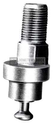
1953 Buick Brake Anchor Pin
The following replacements of Brake Shoes will be made when stock is exhausted:
Group 5.017 -1390942- Set-Brake Shoe and Lining Front (Std.) 1952-70 1st Jobs
To be replaced by:
Group 5.017 -1391154- Set-Brake Shoe and Lining Front (Std.) 1952-70 After Jobs; 1953-70
Group 5.017-1390941 -Set Brake Shoe and Lining Front (.030 O.S.) 1952-70 1st Jobs
To be replaced by
Group 5.017 -1391153- Set -Brake Shoe and Lining Front (.030 O.S.) 1952-70 After Jobs; 1953-70
In both of the above replacements, it will be necessary to order and install the special offset anchor pin when the second type Brake Shoes are installed on a 1st type job.
BRAKE DRUM PAINT
SKYLARK
Because of the fact that wire wheels are standard equipment on all Skylark Models, it is necessary to paint the brake drums to present a good appearance.
Depending upon the color of the car, either red or white paint is used on the brake drums. This is a special paint designed to withstand temperatures up to 800 degrees Fahrenheit without burning off. This, of course, is necessary because of the heat generated when brakes are applied.
Arrangements have been made for this paint to be purchased by dealers directly from Forbes Finishes Division, Pittsburgh Plate Glass Company, 3800 W. 143rd Street, Cleveland 11, Ohio. The paint may be ordered in quart cans as follows:
Color and Number – Approximate Price
S.R. Red 7917 – $6.25 per quart
S.R. White 1476 – 4.75 per quart
These prices are F.O.B. Cleveland, and parcel post or express charges will be added. Please specify method of shipment desired.
We are giving you this information because service brake drums for these cars will not be painted and should it be necessary to replace a drum, or drums, on a Skylark Model the replacement drums will have to be painted according to the color that was on the drums being replaced.
BRAKE SHOE IDENTIFICATION
SERIES 70 ONLY
Some questions have arisen as to the proper identification of the new 12” x 2 1/2” front brake shoes on the Roadmaster series. Production on these shoes was started on Sept. 12, 1952 with Buick Serial No. 16668190. The rear brake shoes on the Series 70 remain unchanged from the 1952 specifications.
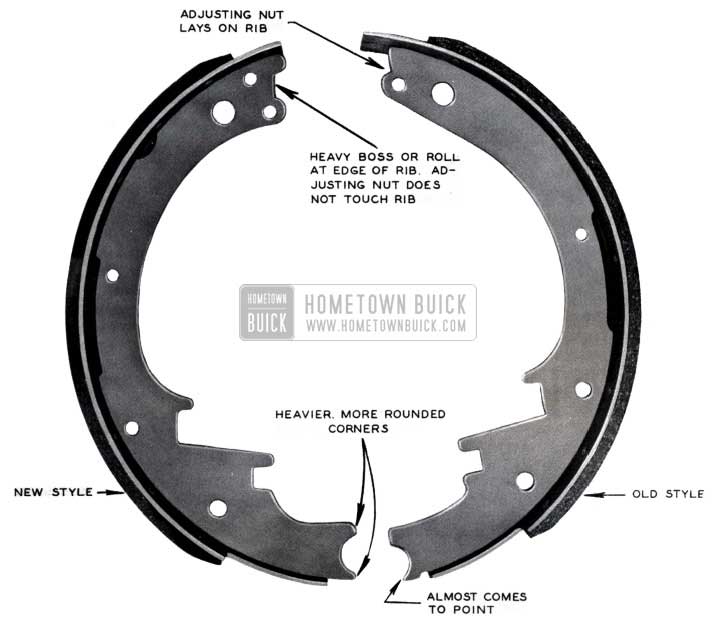
1953 Buick Brake Shoe Identification
Figure 76 illustrates the major points of identification that can be used when attempting to identify the new and old brake shoes. If a job is equipped with the old style brake shoes, this same style must be used in replacing the worn shoes. The new shoes now in production will not properly fit the old style set-up because of the change in geometry by lowering the anchor pin 3/16”. The old style shoes are not interchangeable with present production.
SCREW INTERFERENCE WITH BRAKE LINE
It has been observed that the lower left screw which attaches the fender skirt cover plate to the left front fender skirt on Series 50 and 70 cars protrudes through far enough to contact the left front brake pipe on some cars.
It is possible that sufficient chafing at this point might eventually wear a hole through the pipe. Therefore, it is recommended that this screw be removed from all jobs and discarded. The cover is adequately held in place by the remaining screws. (See Figure 77).
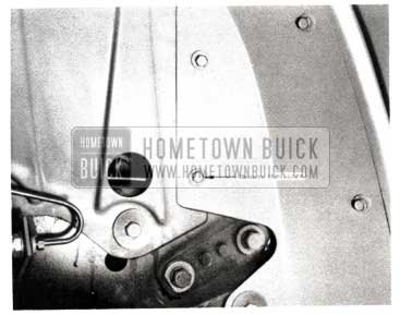
1953 Buick Brake Line Screw Interference
BRAKE PIPE INTERFERENCE
1953 SERIES 40
The front brake pipes on some of the Series 40 cars do not have sufficient clearance at the cross over to the inside of the side rail, under the fender skirt.
To correct this condition the fender skirt is now being changed in production. However, to correct this existing condition in the field, the edge of the fender skirt should be bent up where it interferes with the brake pipe so that the edge of the skirt will not wear a hole in the brake pipe (See Fig78).
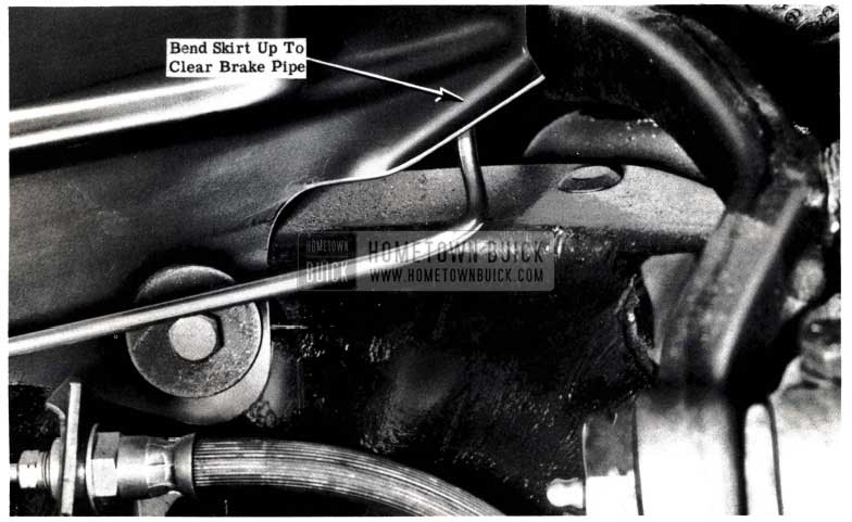
1953 Buick Brake Pipe Interference
It is suggested that the service men on the lubrication rack check, and if necessary, bend the fender skirt as directed above. This can be done as the cars come through for lubrication.
All Series 40 cars brake pipes should be checked for clearance and corrected if necessary before car delivery. All 40 Series produced after Serial No. 16901786 have been corrected.
POWER BRAKE A.DJUSTMENT CHECK
To eliminate the possibility of burning out the brakes on cars equipped with power brakes, it is recommended that the following check be made to insure proper power brake adjustment and cylinder operation at the time of new car make ready.
- Run engine for a period of time sufficient to build up a vacuum supply.
- Turn off engine and wait approximately one (1) minute and apply power brakes. If unit is adjusted and operating properly, the pedal will depress easily for approximately two (2) applications and then hold firm.
If the pedal should not depress easily due to loss of vacuum, it will then be necessary to check the power brake push rod and brake pedal stop for proper adjustments as follows:
- With just the tips of the fingers as a pressure guide adjust the power brake push rod so that it will have approximately 1/16″ endplay.
- Observe the brake pedal stop adjustment and note if the rubber grommet between floor pan and pedal arm is depressed 1/2″ when brake pedal is fully released. If this grommet is not properly depressed, it will have a tendency to hold the brake pedal in and thereby give an improper push rod adjustment. If needed, adjust brake pedal stop for proper grommet depression and readjust push rod.
If adjustments were correct or if adjustments were made, retest the power brake unit as previously outlined. If unit is still losing vacuum, it will probably be necessary to replace the power unit.
It is extremely important that this check be made on every new car prior to delivery of it to the owners.
In addition it is urged that owners of power brake equipped cars be cautioned against “riding” the brake pedal. This should not be done under any circumstances.
POWER BRAKE PEDAL FITTING
EARLY PRODUCTION
To provide lubrication and prevent binding due to rust, the early production power brake pedals (Gr. 4.625) should be changed. This change will cover the addition of a 90 degree Zerk grease fitting to the power brake pedal at the clevis pin which holds the push rod. This change has been made in production effective February 3, 1953, Buick Serial No. 16764228.
Following is the recommended procedure:
- Remove the splash pan covering the starter motor and lower power brake pedal (See Figure 79).
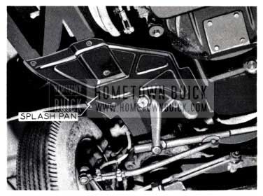
1953 Buick Splash Pan
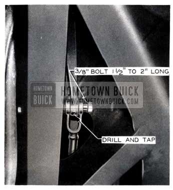
1953 Buick Remove Clevis Pin
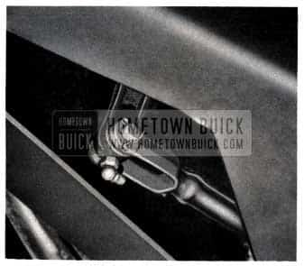
1953 Buick Power Brake Pedal Fitting
CAUTION: Test movement of brake pedal to insure a free and easy movement. No change in push rod adjustment is necessary if rework was properly done and push rod was properly adjusted before rework.
POWER BRAKE LUBRICATION
It has been called to our attention that many dealers do not know that Buick Parts Warehouses have available a 3 oz. can of the special oil which is required for servicing the power brake vacuum cylinders.
This cylinder is lubricated when assembled and under normal circumstances should not require any further service as far as lubrication is concerned. In addition the can of oil is also a part of the overhaul kit. Should symptoms of sticking appear however, it is possible that the cylinder requires lubrication as outlined in the Trouble Shooting Section of the Power Brake Manual. In this case, just the 3 oz. can of oil may be purchased under Gr. 4 .898 Part 1165078.
We cannot recommend the use of any other oil at this time.
POWER BRAKE RESERVOIR BREAKAGE
It has come to our attention that the mounting ears on the hydraulic fluid reservoir for power brakes are breaking due to excessive tightening of the filler plug. (See Figure 82).
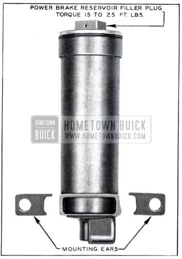
1953 Buick Power Brake Reservoir
It is cautioned that this filler plug should not be torqued to more than 25 ft. lbs. The limit established, 15 to 25 ft. lbs., is the same as that of the regular master cylinder filler plug.
It is suggested that all personnel engaged in the servicing of this unit be instructed of the established torque limits.
EMPTY POWER BRAKE RESERVOIRS
1953 POWER BRAKE EQUIPPED BUICKS
Some cases have been reported of power brake reservoirs being found empty with no evidence of exterior leaks. Naturally the brakes fail, but they operate satisfactory after refilling with brake fluid and performing the usual bleeding operation. These jobs fail again at low mileage with the reservoir again found empty upon inspection.
It is necessary that first a complete check of the power brake unit, lines and hoses be made to be sure that there is no external fluid leaks due to seal or line failure.
This trouble has been diagnosed as a poor fit between the base of the hydraulic cylinder casting and the vacuum can. Apparently on some jobs when the four bolt holes are formed in the can, there is some distortion of the metal around the holes and then the hydraulic cylinder casting does not pull up flush to the can when the four attaching bolts are tightened. This then does not permit equal pressure to the “0” ring seal between the two surfaces and allows vacuum to pull oil from the reservoir pipe past the treads of the retainer holding the seal and primary cup –then into the can up the vacuum pipe and into the engine.
It has since been decided that in any case where there is a noticeable and consistent loss of brake fluid, as evidenced by a low power brake reservoir, a complete, new power brake assembly must be installed.
Brake fluid lossage as measured in the power brake fluid reservoirs of approximately 1″ in six months is not considered excessive, however, a check and record should be made on all power brake units requiring brake fluid addition or brake service.
In the case of complete power brake failure, barring leaking brake lines or other evident mechanical failures, a complete power brake assembly should be installed in the car.
Flat rate time allowance for R&R Power Brake Unit Assembly is 1.6 hr. This time includes bleeding of lines and adjusting of power brake push rod.
POWER BRAKE VACUUM PUMP
1953 SERIES 50 & 70
ALL POWER BRAKE EQUIPPED CARS
Buick now has available an electrical powered “Power Brake Vacuum Pump Installation Kit” Gr. 4.899 No. 1391768. The power brake vacuum pump operates and maintains a vacuum in the power brake system whenever the ignition is “ON” but only when there is not enough engine RPM to produce sufficient current from the generator to cut the pump out. Pump operation, therefore, is controlled by the electrical output of the generator which inturn is dependent on engine RPM. When the engine is running the generator produces sufficient electrical power (only 250 engine RPM needed -normal engine idle 450 RPM) to automatically tum off the vacuum pump. Only when engine RPM falls below 250 RPM, will the pump start up again.
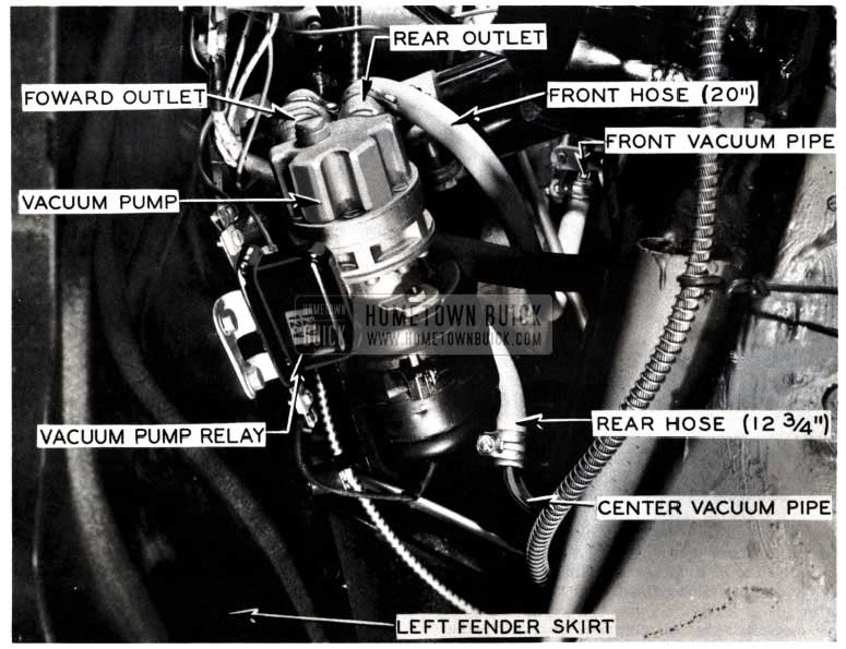
1953 Buick Vacuum Pump
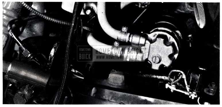
1953 Buick Power Brake Vacuum Pump
Figures 83 & 84 illustrate the position of the power brake pump on the car and Fig. 85 is a line drawing of the wiring hook-up for the unit.
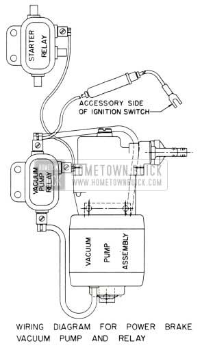
1953 Buick Power Brake Vacuum Pump Wiring Diagram
Included in each pump kit will be a complete sheet of instructions (given below) and a templet to use when drilling the pump mounting holes.
Cars produced after October 1 will have this pump installed at the factory with a corresponding price increase in the price of the power brake option.
The vacuum pump should be checked at least once every 5000 miles and if necessary filled with regular 5- W weight oil. The filler screw on top of the pump is plainly marked.
INSTRUCTIONS FOR INSTALLING THE POWER BRAKE VACUUM PUMP
- Tools required are a 1/4″ electric drill, 15/64 drill, 3/16 drill, center punch and masking tape.
- Disconnect battery cable.
- Remove left ventilator air hose.
- Cut out template and by using masking tape place it in a triangular shaped depression in rear face of left front fender skirt. Template may be placed on rear or front side of skirt. If template is placed in front side of skirt, it will be necessary to mark hole locations on reverse side of template.
- Center punch and drill holes to sizes shown on template.
- Install vacuum pump relay in location shown using the 3/4-14 x 1/2 hex. hd. tapping screws.
- Remove hose which connects the front vacuum pipe to the center vacuum pipe and discard hose.
- Bend the front end of the center vacuum pipe toward the left side until it is parallel to the frame side rail. Bend the front end upward from a horizontal to a vertical position making a short 90 degree bend.
- Using the two 5/8″ hose clamps from the original front vacuum hose, fasten the 12 3/4″ hose to the reworked center vacuum pipe and the 20″ hose to the front vacuum pipe.
- Install the rubber mounting cushions to the vacuum pump and install the pump to the front fender skirt using the No. 12-24 nuts and lockwashers. Rotate pump in bracket 25 degrees clockwise toward rear of car.
- Connect the 20″ hose from the front vacuum pipe to the rear outlet of the pump and connect the 12-3/4″ hose from the center vacuum pipe to the forward outlet of the pump using the 5/8″ hose clamps. (See Figure 83)
- Connect the wires as shown in the wiring diagram, threading the lead wire through the speedometer cable grommet and up to the accessory terminal on the ignition switch.
- Reinstall air hose and connect battery cable.
- To check installation, turn on ignition switch. Vacuum pump should operate when switch is on and engine off. Check brakes for proper vacuum with pump running. When the engine is started, the relay will cut-out and stop the vacuum pump.
FLAT RATE ON POWER BRAKE
VACUUM PUMP INSTALLATION
Power Brake Vacuum Pump – Install 1.0 5-9 (4 .899)
Leave A Comment
You must be logged in to post a comment.