AIR CONDITIONING TEST DATA
To date we have not released any temperatures or pressures for testing car air conditioning equipment to determine whether or not it is functioning within normal limits. We now have some data and are listing it below.
To check a unit the following conditions must be adhered to:
- No sun on car
- Car stationary with all windows closed, trunk lid closed and hood open.
- Fresh air vents at cowl closed.
- Engine speed 1750 RPM.
- Ambient temperature as listed.
- Solenoid valve energized during test.
The following table shows the pressures and temperatures which may be expected after operation of the system for 20 minutes. NOTE: It has been found that approximately twenty minutes operation is required to reach stabilized conditions in the system.
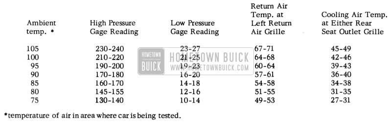
1953 Buick Air Conditioning Pressures and Temperatures
*temperature of air in area where car is being tested.
AIR CONDITIONING SERIAL NUMBER LOCATIONS
So that you will be able to provide serial numbers on Product Quality Reports and Applications for Adjustments pertaining to Frigidaire Air Conditioning equipped cars, we would like to bring to your attention the exact location of serial numbers on the various units of this system.
CONDENSER
The serial number plate on the condenser is located on the liquid outlet end of the condenser assembly as shown in Figure 100.
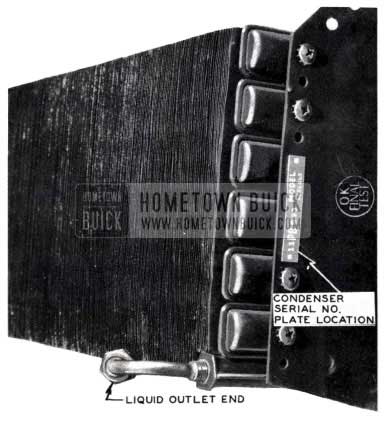
1953 Buick Air Conditioning Condenser
EVAPORATOR
The serial number plate on the cooling unit is located on the front and center of the duct assembly (See Fig, 101).
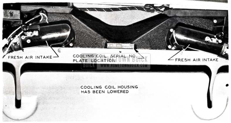
1953 Buick Air Conditioning Cooling Coil Housing
It is necessary to remove upper cover to see the serial number.
COMPRESSOR
The serial number plate on the compressor is located on the upper portion of the shell between the high and low test gauge connections (See Fig. 99).
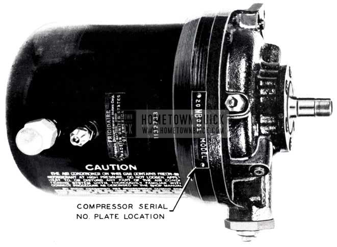
1953 Buick Air Conditioning Compressor
It is essential that these serial numbers be included on Product Quality Reports and Applications for Adjustments so that we can properly identify the exact time at which these units were manufactured.
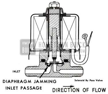
SOLENOID BY PASS VALVE REWORK FOR IMPROPER SEATING
1953 Buick Selenoid By Pass Valve
Fig. 102 is a cross section of a solenoid by-pass valve used in the air conditioned jobs. It has been found that in some cases the rubber diaphragm that seals off the inlet and outlet passages of the valve, is jamming down into the inlet passage opening of the valve thereby holding the valve slightly open even when the solenoid is energized.
By -pass valves with this condition will usually give the same sharp click when energized as on operative valve. However, the cooling unit will not operate properly, if at all, and the pressure on the high and low side of the compressor will not be correct. (See Page 91 of this BPS for correct pressures)The “feel” check should be made on the inlet and outlet lines of the solenoid valve. If the outlet line is cool or cold with the air conditioning unit operating as outlined in “Air Conditioning Test Data” page 91 of this BPS and the solenoid valve energized, indications are the solenoid by-pass valve is leaking.
When it has been determined that the solenoid bypass valve is not seating and holding properly, the valve should be reworked according to the following procedures.
The addition of a strainer screen to the solenoid by-pass valve will correct the folding in of the diaphragm and prevent foreign particals from interfering with the proper seating of the diaphragm.
Strainer screens will be installed in all the field valves that are now in Parts Warehouses. In the event that a field repair necessitates breaking into the air conditioning system, the strainer screen should be installed in the by-pass valve at that time.
The following parts will be carried by the Parts Department for service purposes. For the present, however, the strainer screens may be ordered, free of charge, directly from your Zone Office.
Part Name – Number
Strainer Screen – Gr. 9.198 No. 5915508
“O” ring – body – Gr. 9.198 No.5915532
Body solenoid valve – Gr. 9.198 No. 5915531
Diaphragm – Gr. 9.198 No. 5883746
- Prepare the system for removing the solenoid valve by using service gauges. Also, protect the eyes using safety goggles.
- Follow the instructions for removing and replacing the solenoid by-pass valve as written in the Buick Air Conditioning Manual, Page 41, Item H, Steps 1 through 5.
- Make certain the low pressure and high pressure hand shut off valves at the compressor are closed.
- Disconnect the two flare nuts on the solenoid by-pass valve and remove the assembly from the mounting bracket after disconnecting the electrical leads.
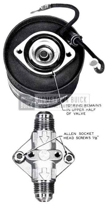
- Invert the solenoid by-pass valve assembly and remove the two allen socket head screws (1/8″).
The „O“ ring will usually remain in the upper half of the valve. (See Fig.103)
1953 Buick Allen Socket Head Screws
Examine the diaphragm, and if it is badly distorted and has taken a “set” it should be replaced.
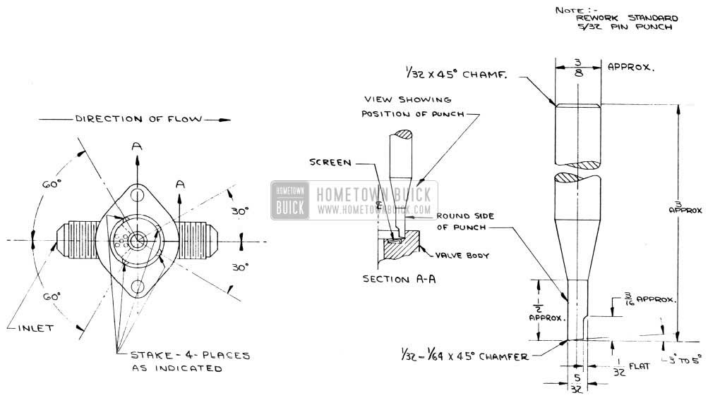
- Secure a standard 5/32″ diameter pin punch and rework by grinding as directed in Fig. 104.
1953 Buick Air Conditioning Inspection
1953 Buick Valve Body Stake Points
CAUTION: Do not mark these locations with a metal scriber, or scratch or nick the flange face of the body, as the „O“ ring gasket must seal against this surface.
Use care in handling of the valve to prevent damage to the flare faces and threads on the flare connection.
The surface of the ring seat in the center of the casting should be protected against damage, such as nicks or scratches as these would cause the valve to leak.
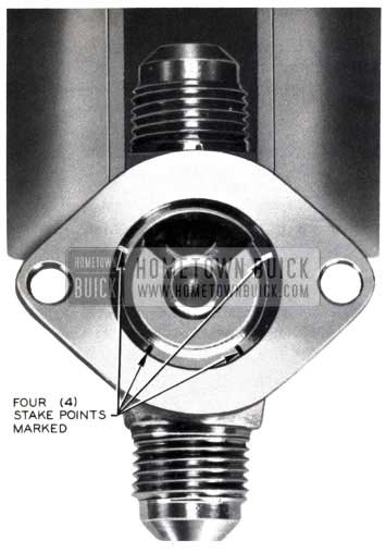
- Place the valve body in a bench vise and lightly clamp on the flat faces near the center of the casting. (See Fig. 105)
- Insert the strainer in the body so that the dished face is on the top side, and the flange edge is turned down. (See Fig.l06)
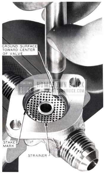
1953 Buick Valve Body Strainer
NOTE: The pilot tip at the center of the diaphragm should be pointing upward toward the plunger seat. (See Fig. 107)
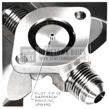
1953 Buick Valve Body Pilot Tip
- Proceed with reassembly of the valve on the car and follow instructions on Page 41, Item H, Steps 6 through 10 in the Buick Air Conditioning Manual.
- Leak test connections which have been disturbed and conduct test to determine proper operation of valve and complete car system. Check for sufficient oil supply in the compressor.
NOTE: Valves which have the strainer assembled in the body at the factory will be identified by a red dot of paint on the solenoid valve shell near the serial number on the name plate. This marking should also be done in the field if the valve has been reworked and the screen installed.
AIR CONDITIONING INSPECTION
Until such time as complete information can be supplied relative to servicing and maintenance operations of cars equipped with Buick air conditioning units, it is suggested that the following check be made on cars so equipped at the time of new car conditioning and also at the 1000 and 2000 mile inspections if the units are being used.
A sight glass has been built into the unit. It is located between the condenser and the radiator grille, close to the splash pan (See Figure 108).
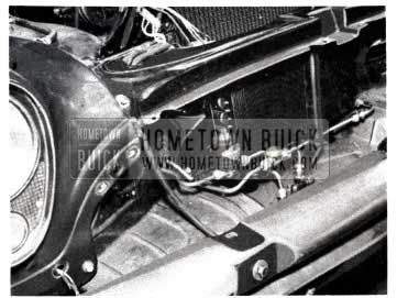
1953 Buick Valve Installed
This sight glass is covered with a hex type cover nut to prevent damage. Following is the suggested procedure for checking the system to see if it contains the proper amount of Freon 12:
- Put system in operation by turning on air conditioning controls for full cooling and running engine at idle speed.
- Remove protective cover nut from sight glass. (See Figure 109)
- Observe sight glass for small bubbles or foam.
If a solid column of Freon is flowing through the sight glass, nothing will be seen because Freon is colorless. If cooling is taking place in the car and nothing can be seen in the sight glass, it may be assumed that the system is O.K. and contains the proper amount of Freon. If the system is low on Freon or contaminated, bubbles or foam will appear in the sight glass. In s
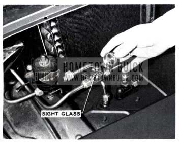
1953 Buick Valve Sight Glass
uch instances it is suggested that you contact your Zone Office.
AIR CONDITIONING SIGHT GLASS CHECK AND MANUAL CHANGE
We wish to bring to your attention the fact that in certain instances bubbles in the sight glass DO NOT necessarily indicate a condition of low Freon in an air conditioning system.
In certain situations, bubbles may be trapped in the air conditioning sight glass thereby giving a low Freon indication when actually the system may just be operating through the solenoid by-pass valve.
On Page 48, Section b-3 and 4, and d-3 and 4 in the Manual, the instructions are to operate the system for ten minutes at 1600-1700 RPM’s and then check the sight glass for a shortage of refrigerants. In some cases, the system will have cooled the car interior down to the point where the system will be operating through the by -pass after ten minutes of operation with the thermostat controlling the solenoid. With the system on by-pass, the refrigerant tends to lie idle in the sight glass or give a slight bubbling indication which, even though normal under the circumstances, can easily be taken for a shortage of refrigerant since this fact is not described as such in the Manual.
It is suggested, therefore, that when checking a unit for Freon the solenoid by-pass valve be energized thereby insuring full circulation of the Freon in the system.
AIR CONDITIONING
COMPRESSOR
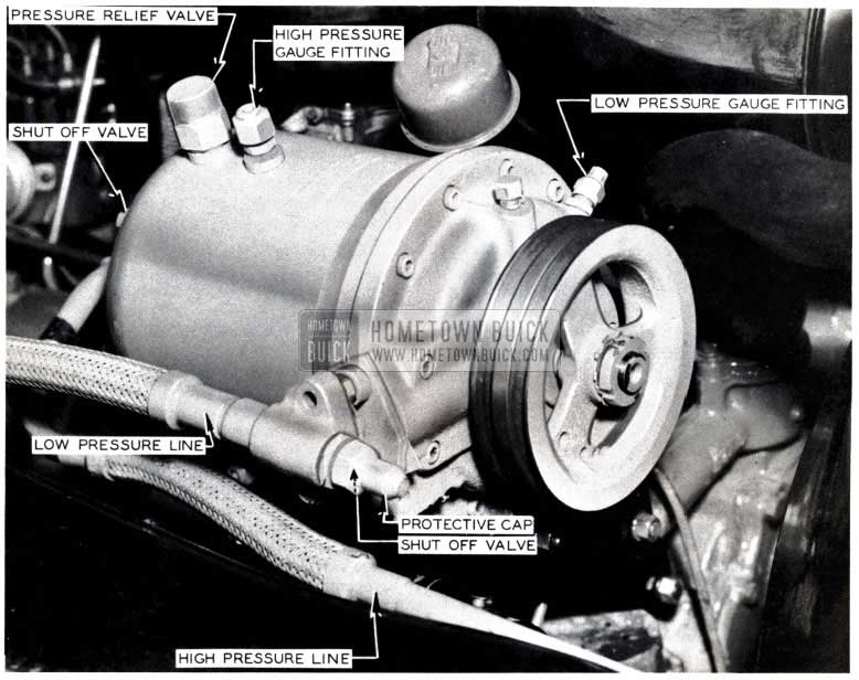
The refrigeration compressor is located directly above the generator on the right side of the engine. The compressor is driven by two “V” belts from the crankshaft pulley. Two lines connect the refrigerating system to the compressor. The high pressure line connects at the rear end of the compressor body and the low pressure line connects at the front side of the compressor body. (See Fig. 110)
1953 Buick Air Conditioner Compressor
Each line contains a shut-off valve located at the point where the line attaches to the compressor. These valves are operated with a 1/4″key and cannot be operated until the hexagonal caps are removed from the valves. Closing these valves shuts off the entire system from the compressor.
CAUTION: The compressor should not be operated with the high pressure line valve closed. In addition to the manual valves there are special Schrader type valves in the compressor at the points where the two lines attach. These internal valves automatically close, sealing the compressor when the lines are removed from the compressor body.
Located on top of me compressor body are the high and low gauge line fittings. These fittings are capped with protective covers and contain the special Schrader type valves which seal the compressor from outside air.
To Remove the Compressor:
- Remove covers from high and low line valves at compressor. When removing covers always hold mating fitting with a wrench to avoid loosening it too.
- Using 1/4″ square key or square socket, close the high and low line valves tightly by turning clockwise.
- Remove protective covers from low and high pressure gauge fittings on top of compressor, being sure to hold fitting from turning with a wrench.
CAUTION: Wear protective goggles as some fluid may escape under the slight pressure left in the compressor.
- Remove the high and low pressure lines by removing the two bolts attaching each fitting to the compressor. Cover the compressor openings and the pressure line openings with masking tape to keep out dirt.
- Remove belts from compressor pulley by moving generator inward. This loosens the driving belts and permits easy removal.
- Remove compressor from bracket by removing four attaching bolts and nuts.
To Install Compressor:
- Reinstall compressor to brackets, assemble belts and tighten belts to 5/16-3/8″ deflection midway between the fan and compressor pulleys. Belts are adjusted by generator movement.
- Install the two new „O“ ring seals (Group 9.240, No. 5887997, same number for both seals as they are identical and interchangeable) on the high and low pressure line fittings. Care must be used in removing the old „O“ ring seals so as not to mar or scratch the adjacent surfaces. These „O“ ring seals are seated in a grooved recess of the valve. Carefully cutting the “0” rings with a sharp knife is the best method of removal.
- CAUTION: Carefully insert high and low line fittings into their respective bores in the compressor, being careful not to damage the new „O“ ring seals.
- Tighten lines evenly to compressor body.
- Crack open the high pressure line valve on rear of compressor with the valve key.
- Depress the Schrader valve in the low pressure gauge line fitting and allow pressure to escape for a few seconds. (This will purge any air from the compressor.)
- Open the high and low line valves all the way by turning counter-clockwise. These valves must come against their seats in the open position as they seat against a seal.
- Replace protective covers on line valves and gauge fittings.
- Test for leaks at the compressor fittings, using Leak Detector No. J-5419 in accordance with instructions furnished with the detector. CAUTION: Do not under any circumstances disconnect lines at any point except as covered above until complete instructions are received. Should any part of the system become damaged, Freon and lubricating oil will escape. Should this happen, serious damage to the compressor will result unless the drive belts are removed immediately. In addition, close the valves on the high and low side of the compressor and seal any openings caused by damage with masking tape to prevent entrance of dirt and moisture. Contact your Zone Office for further instructions.
IMPORTANT: Do not steam clean any portion of the car adjacent to refrigerator units or lines. Abnormal heat on any portion of the refrigeration system will quickly cause Freon to boil, resulting in excessive pressures.
AIR CONDITIONING COMPRESSOR VIBRATION
ALL 1953 AIR CONDITIONED JOBS
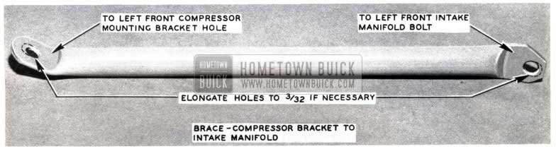
An effective method of reducing noise and vibration in Air Conditioning Compressors is by using a compressor brace. (Figure 111)
1953 Buick Air Conditioning Compressor Bracket
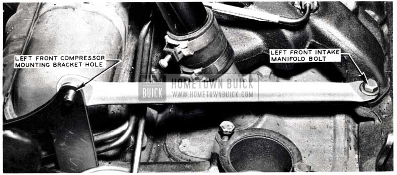
This brace, Gr. 9 .171 Part No. 1165949, is to extend from the front bracket, inner compressor mounting bolt to the intake manifold to head mounting bolt as illustrated in Fig. 112.
1953 Buick Front Intake Manifold Bolt
Bolts one-eighth inch longer are to be used at these two mounting locations to accommodate the increased thickness of metal. The two brace mounting holes may have to be elongated to correct for length.
AIR CONDITIONING COMPRESSOR BELT CLEARANCE
ALL AIR CONDITIONED JOBS
1953 Buick Air Conditioning Compressor Belt
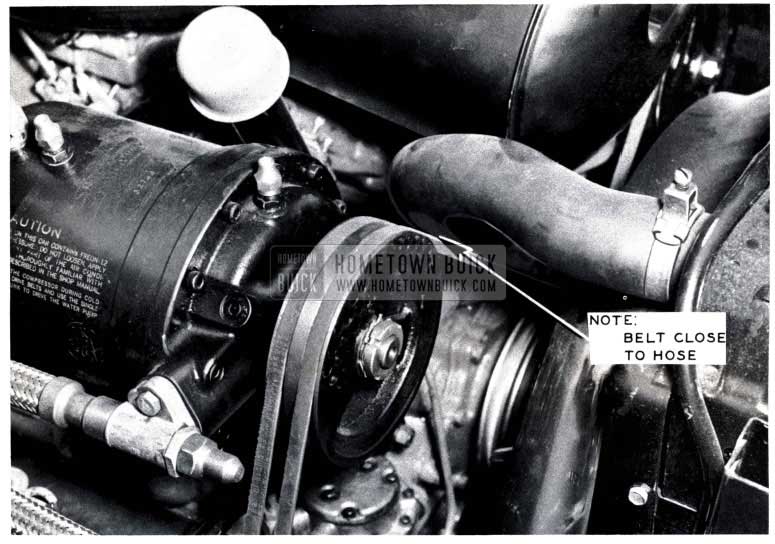
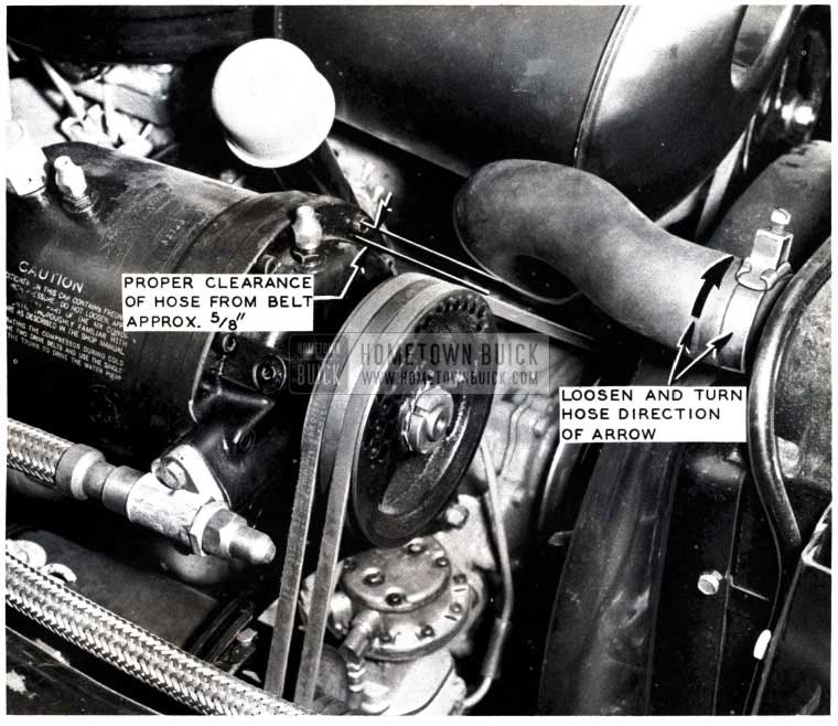
Fig. 113 illustrates a condition occurring on some Buicks equipped with an Air Conditioning unit. As shown in Fig. 113, the upper radiator hose is in a position to rub against the Air Conditioning Compressor belts, thus causing damage and eventual failure of this hose.
By loosening the top radiator hose clamp and turning the radiator hose, it will properly position itself as shown in Fig. 114.
1953 Buick Air Conditioning Hose
In this position, there should be approximately 5/8″ clearance between the Air Conditioning compressor belts and radiator hose.
In some cases the standard upper radiator inlet hose has been installed on cars equipped with Air Conditioning. This standard radiator hose will not properly fit around the Air Silencer and pump belts and must be replaced with upper radiator inlet hose Gr. 1.159, No. 1318967 especially designed for use on jobs equipped with Air Conditioning.
SERVICE REPLACEMENT COMPRESSORS
A correction has been made in the manufacturing of Air Conditioning compressor seals. We will therefore identify all compressors with the corrected seal by stamping a letter “G” on the serial plate and on the exterior of the service crate. If compressors are received that do not have the letter “G” stamped on the crate or serial plate, the serial number of the compressor will be a guide as to whether the compressor has the new type seal. Beginning with Serial No. 32.MB495, all compressors will have the new seal assembly. New compressors may or may not have the letter “G” stamped on them.
It is suggested, therefore, that your present stock of Air Conditioning compressors be checked as to whether they are equipped with the new type seal using the above information as a guide.
RETURN OF INOPERATIVE AIR CONDITIONING COMPRESSORS
In order to assist both the Buick Engineering and Service Departments in analyzing compressor failures, AFA’s covering these failures should be submitted the same day the compressor is replaced or not later than the following day. Immediate handling in this regard also assists us in maintaining adequate stocks of new compressors. AFA’s should include the compressor serial number.
To adequately protect compressors being returned to your Zone Office, we are requesting that inoperative compressors be returned in the same crate in which the new compressor was received. Return these compressors, transportation prepaid, directly to: Your Zone Office.
In returning compressors, please use freight which is the least expensive. Prepaid transportation receipts must be attached to the AFA before forwarding it to the zone.
Whenever possible please answer the following questions on the AFA and also on the tag accompanying the returned compressor.
- Was there evidence of seal leakage?
- At what speed was car being driven at time of failure?
- Was air conditioning system in operation at time of failure?
- What was outside temperature at time of failure?
SUMMARY
- AFA’s should be submitted the same day or no later than the following day.
- Crates used for shipment of new compressors should be used for the return of inoperative compressors.
- Please return compressors by freight.
- Answer the questions when possible and please include any pertinent information which may help us to determine the cause of the failure.
AIR CONDITIONING COMPRESSOR DISCHARGE LINE REPLACEMENT & FITTING
ALL AIR CONDITIONED CARS
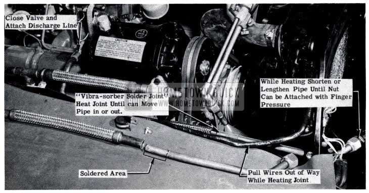
When it becomes necessary to install the compressor to condenser discharge line Gr. 9.225 No. 5882761 (compressor to condenser, See Fig. 115) it should be noted that this line can and must be adjusted to fit without tension and/or torsion between these two units.
1953 Buick Air Conditioner Assembly in Engine Compartment
The compressor discharge line has a “vibrasorber soldered joint” which when heated may be adjusted to give the desired length. When fitting, the flexible part of the discharge line should be almost straight, allowing just the slightest sag for vibration and engine movement take-up. Following is the suggested procedure for installing the compressor discharge line:
- Close the valve in the new compressor discharge line before attaching it to the compressor.
- Position the line through the radiator baffle plate and attach line to rear of compressor.
- Prepare to attach front of discharge line to the condenser inlet line and note whether line needs to be shorter or longer.
- If necessary, heat the “vibra-sorber soldered joint” and move pipe until the front connection can be easily attached. (If necessary to add solder to secure joint, use only 95-5 type solder)
NOTE: A piece of asbestos or similar heat and flame resisting material must be used to protect the area. Pull wiring harness up out of way as illustrated in Fig.115.
- Remove heat from joint and allow a few minutes for solder to set.
- Use procedure required to put system back in operation and test all new connections for leaks.
COOLING UNIT LEAKS
AIR CONDITIONED JOBS
On air -conditioned cars if water leaks out of the splash pan of the evaporator (cooling unit) into the trunk area, it is an indication that the cooling unit drain tubes have become plugged. The plugged drains cause the water to back up in the unit and overflow into the trunk area. It is recommended, therefore, to rework the drain tubes on cars having this trouble.
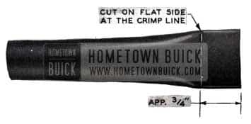
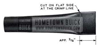
To rework the drain tubes, remove them from the cooling unit and cut the crimped end off as illustrated in Fig. 116.
1953 Buick Cooling Unit
The tube is to be cut at the crimp line on the flat section. Do not use tubes if they have been cut too far up or cut on the curvature to the flat. The tube, after rework, should still be closed on the bottom to prevent any suction of dirt.
PLUGGED EVAPORATOR DRAIN TUBES
ALL AIR CONDITIONED CARS
Cases of plugged drain tubes especially due to undercoating have caused considerable trouble in the field. We again wish to mention that plugged drain tubes will cause an excessive amount of water to collect in the evaporator unit. In some cases this water may leak out of the evaporator and cause considerable damage to the luggage or items in the trunk. For this reason it is imperative that the evaporator drain tubes be checked to see if they are open and draining properly. As stated, this condition is especially prevalent on cars that have been undercoated, and these jobs should be given special attention.
RELOCATION OF EVAPORATOR DRAIN HOLES
ALL AIR CONDITIONED CARS
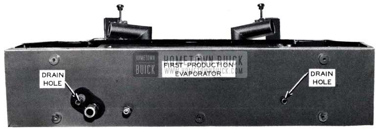
To improve the drainage of the evaporator and blower assembly, the drain holes in the drain pan have been relocated and the rubber drain tubes have been changed from a straight to bent tube. This change went into production with Serial Number 17045011.
1953 Buick Air Conditioning Evaporator
Fig. 117 is an illustration of the first or early production evaporator. Note the position of the drain holes in the first production evaporator as compared to those of the after production evaporator as shown in Fig. 118.
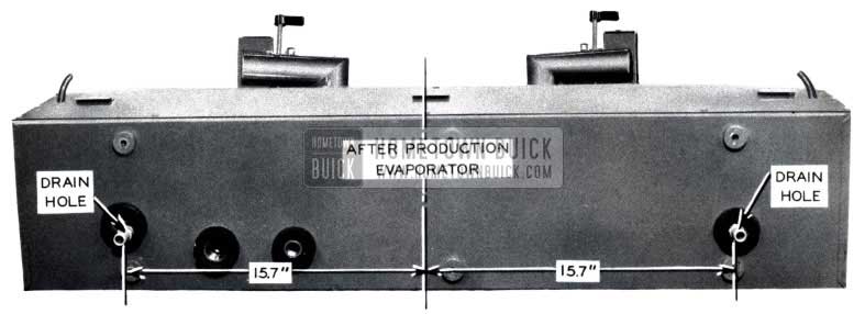
1953 Buick Air Conditioning New Evaporator
On the after production evaporator, the drain holes have been moved outward to a dimension of 15.7″ from either side of the evaporator centerline.
If it becomes necessary to replace one of the early production evaporator coil shells and installation (housing) with after production parts, it will be necessary to drill new drain hole outlets in the under pan of the car body (See figure 119)
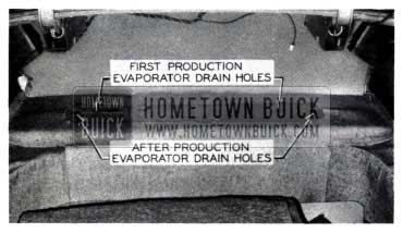
1953 Buick Air Conditioning Evaporator Drain Holes
Rubber grommet Gr. 9.775 No. 1340390 in conjunction with Buick Sealer Specification No. 873 or Minnesota Mining’s Body Sealer Compound No. EC-852 should be used to seal the open drain holes in the under pan of the car body left by the first production evaporators.
CORRECTION FOR EVAPORATOR WATER LEAKS
Some early model air conditioning evaporator units may have caused trouble by leaking water into the trunk area. Following is a procedure designed to eliminate these water leaks. A complete kit for the rework is available through the Parts Department and should be ordered under “Air Conditioning Evaporator Sealing Kit,” Gr. 9.282 No. 5876574.
Flat Rate time allowance is 7 1/2 hours.
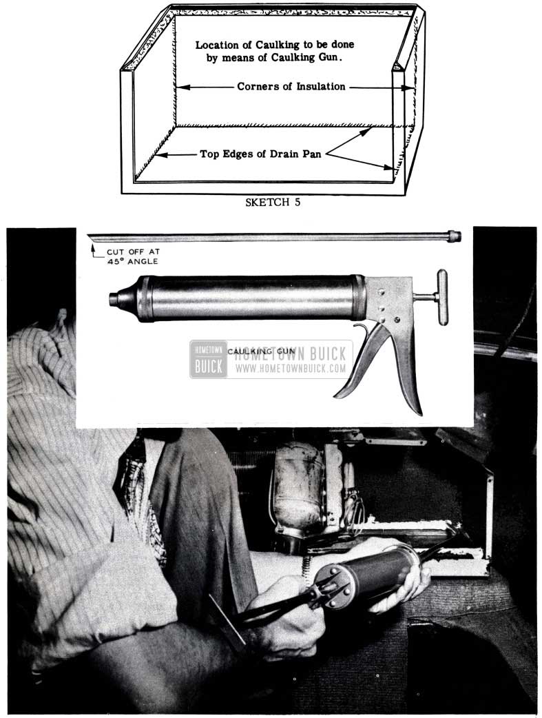
It will be necessary to purchase a caulking gun similar to the one illustrated in Fig. 127 (inset). The caulking gun should be of the non-cartridge type. It will probably be necessary to rework the caulking gun nozzle to the desired length of 15″ or build a nozzle to that specification as a nozzle of this length is usually not available. A gun suitable for this work can be ordered from the “Kenmar Mfg. Co., Albert & Manha Streets, Philadelphia 25, Pa. The order should specify a model 32 caulking gun with only a No. 11 nozzle. This nozzle is 18″ long and therefore should be shortened to 15”, cut at a 45 degree angle.
Before beginning any of the repair operations, it is vitally important that you READ THE ENTIRE DETAILED PROCEDURE very carefully. This will greatly assist you in planning your work.
As a further assistance to you in organizing your work before beginning work, you should immediately assemble the following tools:
- One No. 2 Phillips screw driver.
- One 12′” blade (or longer) flat tip screw driver.
- One putty knife.
- Quantity of clean rags.
- A can (or bottle) of clean naphtha type solvent.
- One pair of tin snips. NOTE: If tin snips are not available, use a hack saw.
- One 1/8″ drill.
- One electric drilling machine.
- One sharp knife for cutting insulation.
- Caulking gun 15″ nozzle.
- Large fender cover.
Your evaporator repair kit should contain the following. Check to be sure the kit is complete before starting the rework.
- 2 Fan motor support plates
- 4 Fan inlet cones
- 1 Evaporator cover panel assembly
- 2 Sponge rubber pads
- 1 Sponge rubber strip – Plevum
- 1 Brass strip .032″x 1 1 j4″x 41 7 /8″
- 2 Brass corners
- 1 Self sealer strip
- 12 Screws P.H. No. 10 x 1/2″
- 2 Screws P.H. No.8 x 1/2″
- 1/2 Pint caulking material, Extruded caulking compound six strips, Instruction sheet
DETAILED PROCEDURE
- Operation necessary to rework drain tubes located outside the body underneath the air conditioning unit.
- Remove both drain tubes.
- Check to determine if any foreign material has accumulated in these and thus has prevented proper drainage of the condensate.
- Cut off ends as illustrated in Fig. 120.
1953 Buick Air Conditioning Drain Tube
Listen closely for any metallic noise emanating from the blower assembly.
NOTE: Any such metallic noise indicates that the fan wheel is contacting the blower housing. The possibility of such metal contact must be removed. The method of correction will be explained in Section D of this procedure.
Before starting rework, place shop cloth or similar protective covering in the trunk to prevent damage and/or soiling of rear trunk compartment trim.
- Remove both blower assemblies from the evaporator unit.
Procedure:
- Remove the two access covers from the back side of the air conditioning unit.
- Disconnect the electrical leads to the blower motor.
- Remove the metal strap which secures the rubber outlet tube to the blower duct.
- Remove the screws which hold the blower assembly to the air conditioning unit housing.
- Remove the blower assemblies from the housing.
- Make necessary corrections to the blower assemblies.
Noise because of metallic contact:
NOTE: Completely finish the work on one assembly before starting the second. In that manner one can serve as a model for the other.
- Remove the motor and wheel assembly from blower housing. (See Fig. 121)
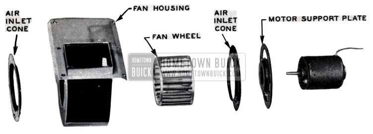
1953 Buick Air Conditioning Fan House
NOTE: During the operation of applying the new air inlet cones and the heavier motor support plates to each blower assembly, each assembly (and all its parts) must be kept positively apart from the other. If the wheel or the motor of one is applied to the other, it will result in completely incorrect fan operation.
- Apply new motor support plate to fan motor. (See Fig. 121)
- Place one new inlet cone over end of motor shaft. (See Fig.l21)
- Apply fan wheel to shaft.
- Permit 1/16″ clearance between side of fan wheel and inlet cone.
- Tighten fan wheel set screw just snugly.
- Apply motor support plate with its accompanying inlet cone to blower housing.
NOTE: Be certain that the motor is applied to the proper side of the blower housing. Only one side is correct. In the evaporator unit, the blower assemblies may be classified as one left and one right assembly - Apply three extra sheet metal screws for holding the blower motor support plate against the side of the housing.
NOTE: This refers to those housings having only three screws on the side. Some of the blower assemblies already have six.
If the three additional screws must be added, the additional holes must be drilled with a 1/8″ drill. (See Fig.122)
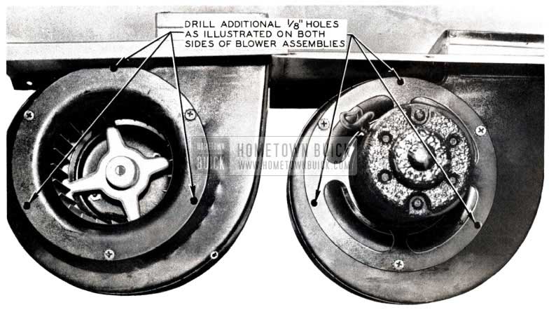
1953 Buick Air Conditioning Blowers
- Cut away metal comers from the two screw holes at the end of the blower assembly support plate that extends toward front end of car after application.
- Purpose: To facilitate re-installation of blower assembly.
- Details of metal removal: Refer to Fig. 123, Sketch No. 1.
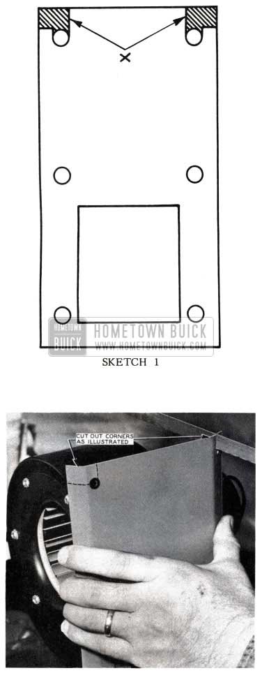
1953 Buick Reinstall Blower Assembly
Part of metal to be removed from each motor support plate is indicated by X. The purpose of removing this metal is to .facilitate the replacement of the blower assembly. Before replacing the assembly, apply two No. 8 hex head sheet metal screws to the rear screw holes for each blower housing opening. Drive the screws in to one half of their length. After the blower assembly is in place, apply the remaining four No. 8 hex head sheet metal screws to each blower assembly. At this point, all six screws may be tightened in each blower assembly.
NOTE: If the piece of black non-flexible insulation is not cemented to the back under side of the blower assembly support plate, dispose of that loose piece. In its place, apply with the proper cementing procedure the piece of 4-1/4″ x 4-3/4″ soft sponge rubber of which two are contained in the repair kit.
- Proper position: See Sketch 2 & Fig. 124.
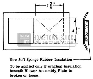
1953 Buick Blower Assembly Plate
1953 Buick Blower Assembly Support Plate
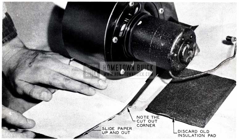
- Apply cement to forward underside of blower assembly support plate.
- Apply cement to one side of soft rubber.
- Permit a sufficient length of time to elapse until the cement is not tacky to the touch.
- Place a piece of clean paper beneath the sponge rubber and then position the sponge rubber exactly in position on the blower assembly support plate. Fasten perhaps 1/8″ of one end of the rubber to the part of the support plate next to the fan outlet.
- Pull out paper gently. (See Fig.124)
- Press sponge rubber firmly in place.
NOTE: Extreme care must be used to avoid cutting or otherwise penetrating the surface of the insulation lining the interior of the evaporator casing.
- Method of removal:
- By means of an ordinary “putty” knife, slice off all the old sealing compound from all accessible surfaces of non-flexible rubatex insulation and from the edges of the drain pan. Any old sealing compound lying inside the drain pan should be removed. (See Fig.l25)
1953 Buick Remove Drain Pan
NOTE: Do not use gasoline under any circumstances. Gasoline will leave a bad odor afterward in the air conditioning unit.
CAUTION: As with all naphtha type solvent, great care must be taken to prevent any contact with a flame during the cleaning process.
NOTE: If any piece of the interior evaporator insulation is found broken or loose, those pieces must be re-cemented in place.
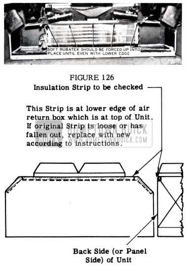
Insulation piece along lower edge of return air box.
NOTE: If this piece of non-flexible material has fallen out (or is loose) it should be replaced with the narrow strip of soft rubatex to be found in the kit. This piece of soft rubatex should not be cemented. It should be pushed in place (aided by a putty knife) until the lower edge of the soft narrow rubatex strip is exactly at the lower edge of the return air box. (See Fig. 126 & Sketch 3)
1953 Buick Air Conditioner Return Air Box
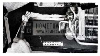
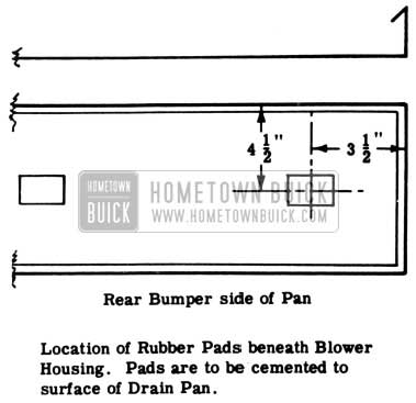
- Check location of the rubber pad which is cemented to the drain pan at a point just below the blower fan housing.
NOTE: The purpose of this little pad is to prevent any metal contact between the fan housing and the pan. If the pad is loose it may move over to cover the condensate drain opening in the pan.
For exact location, see Sketch 4 & Fig. 125.
1953 Buick Blower Housing Rubber Pads
- Application of a soft Presstite caulking compound No. 422.5.
NOTE: By means of caulking gun having the 15” long nozzle, apply a thin bead of this compound to the following edges or comers: (See Fig 127 & Sketch 5)
1953 Buick Caulking Gun
- Along the junction of each of the drain pan and the vertical sides of the insulation at the end of the evaporator housing.
- Along the junction of the back side of the drain pan and the insulation at the back.
NOTE: The greater portion of this junction is beneath the cooling coils and therefore is quite inaccessible. In consideration of the caulking of this junction, it must be done with extreme care and patience. - Along two vertical comers formed by the insulation at the back of the evaporator casing and the vertical insulation at the ends.
NOTE: See Fig. 128 for illustration of soft caulking location.
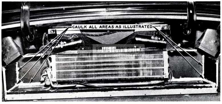
1953 Buick Caulking Areas
- Install blower assemblies.
- Application of metal strip.
- Size: 41-7/8″ long- 1-1/4″ wide.
- Location: Between front edge of drain pan and lower piece of insulation. See Sketch No. 6 & Fig. 129.
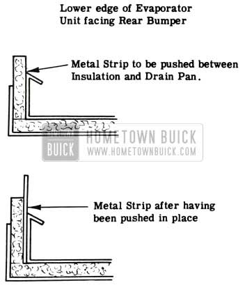
1953 Buick Lower Edge of Evaporator Unit
1953 Buick Back Corner of Drain Pan
CAUTION: Great care must be exercised to prevent the metal strip from cutting into the non-flexible strip of insulation. No part of this insulation must be between the metal strip and the drain pan.
NOTE: These are left and right hand comers.
- Purpose: To reinforce ends of long metal strip.
- Location: Around back comer of drain pan. (See Fig. 129 & Sketch 7)
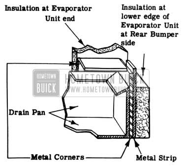
1953 Buick Installation at Evaporator Unit
Side of comer that has no bend at top must go between the long straight metal strip just installed and the drain pan.
NOTE: The side of the comer that has the 90 degree bend at top should carry a film of soft caulking material between itself and the insulation and thus prevent leakage of condensate past that point. However, to be certain of a seal, after the corners are in place, the soft sealing compound should be pressed in over their edges where they contact the interior insulation.
- Application of 3/4” wide soft sponge rubber gasket to the outer surface of long metal strip.
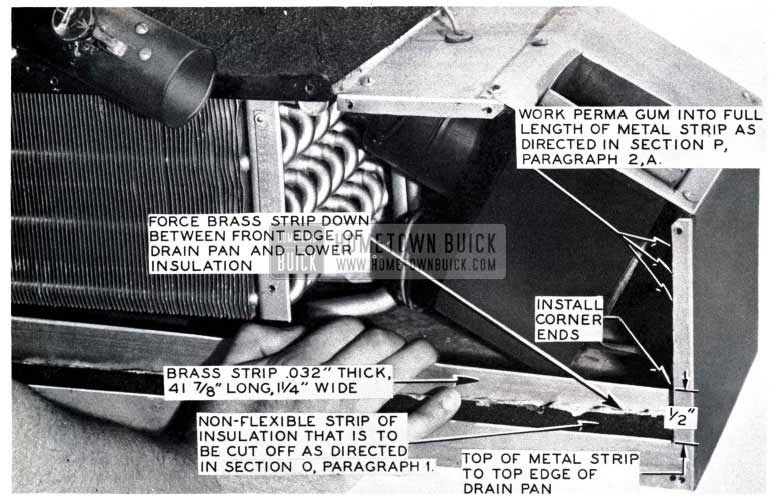
- By means of a knife, cut away the non-flexible insulation on a line level with the lower front edge of the evaporator casing. (See Fig. 129 & Sketch 8)
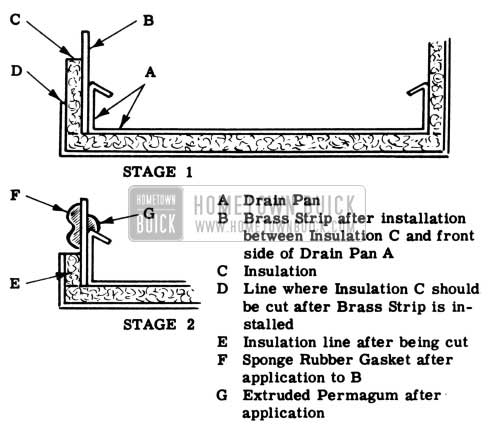
1953 Buick Front Edge of Evaporator Casing
- To the junction formed between the inside surface of the metal corners, and the back edge of the drain pan.
- Have hands clean and free from any grease or other matter.
- Place very carefully a strip of the extruded perma-gum along the junction formed between the inside surface of the long metal strip, the inside surface of the metal corners, and the top edge of the drain pan.
- By means of fingers, push the strip of perma-gum tightly into the entire length of the crevice between the metal strip and the drain pan. Check work with a mirror, checking along back edge to insure good adhesion between metal strip end inside top edge of drain pan.
- To the joint formed between the edge of the sheet metal and the insulation where the back panel fastens to the ends of the casing.
- Work perma-gum well by pressing in with fingers a small quantity of the compound into the space formed between the vertical edges of the insulation and the outside casing. (See Fig.l29)
- Purpose: To prevent any seepage of condensate between the interior insulation of the air conditioning unit and the casing.
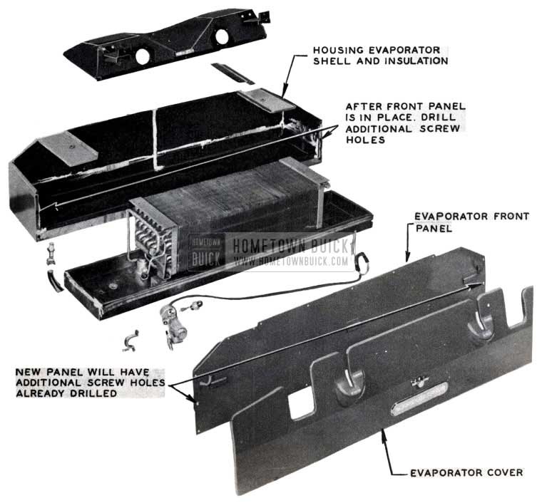
- Discard old back cover panel and install new cover panel furnished in repair kit.
- Need for drilling two extra holes in evaporator case.
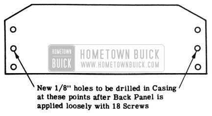
NOTE: In order to apply more pressure on the gasket now placed over the entire inside surface of the back panel, one new screw must be provided at each end in the casing. When back panel is applied and all former 18 screws are in place, the new holes in the vertical edges of the end of the casing may be provided by running a 1/8″ drill thru the new screw openings already provided in the panel. (See Fig.l30 & Sketch 9)
- Need for drilling two extra holes in evaporator case.
1953 Buick Air Conditioning Evaporator Assembly
1953 Buick Evaporator Casing
AIR CONDITIONING FILTER MAINTENANCE
Air conditioned cars are equipped with an air filter beneath each “return air” grille at the rear seat package shelf. These filters are removable for cleaning.
Since it is difficult to determine a definite mileage interval because of various operating conditions, we recommend that the filters be inspected by looking at them thru the return air grilles at say 1000 mile intervals until some definite cleaning interval can be established for that particular car.
These filters may be removed and cleaned when it appears necessary, as follows:
- Remove cooling unit cover.
- Reach up under the return air grilles and slide out the filters.
- Clean with gentle spary of cold water and allow to drain. If it appears necessary, a mild detergent may be used provided filter is rinsed out thoroughly afterward to remove any film from the filter strands.
LOOSE HEADLININGS AT GRILLE OPENINGS
ALL AIR CONDITIONED CARS
There have been reports from the field that in some cases the headlining around the inside roof air ducts on air conditioned cars has come loose. This condition should be corrected in the field wherever found to prevent the loose lining from covering the grille opening.
In production the headlining is originally glued to the air duct. Therefore, when repairing a loose headlining, DO NOT CUT the headlining to fit AROUND the air duct but re-glue excess material to the inside of the duct. 3-M fabric glue or comparable adhesive is suggested. Trimming of the headlining to fit the air duct will not leave enough material for gluing it to the duct and subsequent headlining shrinkage will tend to pull the lining completely away from air duct.
COLD WEATHER OPERATION OF AIR CONDITIONING UNIT
ALL AIR CONDITIONED CARS
It is recommended that during periods when the outside air temperature is consistently below 45 degrees F. the air conditioning compressor belts be removed and the auxiliary fan and generator belt supplied in the trunk be installed. When the air temperature is 45 degrees F. or below, the refrigerant and oil in the air conditioning system tend to collect and build up in the coldest spot which would be the condenser.
This condition could starve the compressor of refrigerant from which it is lubricated. The outcome of operating under this condition might cause compressor seizure.
At the time of this belt change it is also suggested that the fresh air vents in the evaporator (control knobs in trunk) be closed to the winter position.
“FREON 12” CYLINDER HANDLING
DICHLORODIFLUOROMETHANE (Freon-12”)
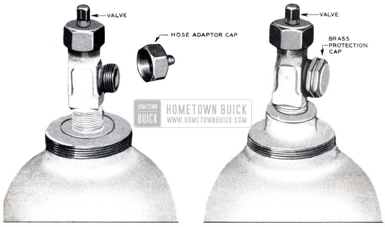
Every precaution should be taken to avoid drawing liquid refrigerant or oil into a cylinder when dis charging the cylinder contents. The valve should be losed immediately after the cylinder has been emptied.
As soon as the cylinder is emptied of refrigerant, valve closed and cylinder disconnected from the system, the brass protecti6n cap should be placed on the outlet connection of the valve so as to prevent dirt from entering the valve and also to prevent damage to the threads on the valve connection: Cylinder hoods should be carefully screwed in place on the cylinder after use and before placing cylinder in stock or returning to manufacturer. (See Figure 131)
1953 Buick Freon 12 Cylinder Handlig
Should it become necessary to warm the Freon-12 cylinder to promote a more rapid discharge of gas, extreme care should be taken to prevent cylinder temperature above 125 degrees F. as the fusible plugs (See Fig. 132) in the cylinder and valve have a melting point of 157 degrees F. and soften at a lower temperature.
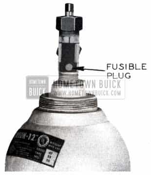
1953 Buick Freon 12 Cylinder
Never permit live steam to blow on the cylinders or the fusible plug safety devices and never apply a direct flame against a cylinder or valve.
Store cylinders upright and in a cool, dry place whenever possible. Keep cylinders away from salt or other corrosive chemicals or fumes as rusting will cause damage to the cylinders and the cylinder hoods to stick.
Proper protection should be afforded the eyes by the use of goggles or large lens spectacles to eliminate the possibility of liquid Freon-12 from coming in contact with the eyes and causing possible injury due to the freezing of the moisture in the eye. Should the liquid gas come in contact with the eyes the person suffering the injury should be taken at once to a good eye specialist. Avoid rubbing or irritating the eyes and give the following first aid treatment immediately.
- Drops of sterile mineral oil should be introduced into the eyes as an imigrant.
- The eyes should then be washed if the irritation continues at all with one of the following:
- A weak boric acid solution
- A sterile salt solution not to exceed 2% sodium chloride.
Should the liquid gas come in contact with the skin the injury should be treated the same as though the skin had been frost bitten or frozen.
- Wash affected area with cold water.
- In extreme bum cases, consult the local designated factory or shop physician.
Should any person be overcome in a space which lacks oxygen because of high concentrations of Freon-12 being present such person should be treated in the ordinary manner of people who have experienced suffocation, through artificial respiration produced manually or by a pulmotor.
Leave A Comment
You must be logged in to post a comment.