DYNAFLOW CAMPAIGN
On Flint built Dynaflow cars with approximate starting serial no. 16833391 and ending with serial no. 16838670, there is the possibility that a pressure regulator valve was installed in the Dynaflow which did not have a bleed hole through the narrow end land. This can, in the case of cold oil, cause rather high pressures in the transmission. For this reason all cars between the above serial numbers and containing Dynaflow transmission numbered from H or J-094 through H or J-100 should be checked.
The check can easily be made by removing the transmission oil pan and the plug from the valve body which houses the pressure regulator valve. A glance at the end of the valve will immediately reveal whether or not the valve has the required .040” hole in it. If the hole is not present, the valve should be replaced.
The reason we do not recommend the use of a pressure gage in the front pump line is because if the transmission and oil are reasonable warm, gage pressures might not be excessively high and, therefore, would not show up an undrilled valve.
Should you be required to service any Dynaflows for excessive or persistent oil leaks or other indications of high pressures, always check to see that this valve has a bleed hole in it.
Flat rate time for this check is 1.1 hrs. More than one car may be listed on an AFA providing all serial numbers are shown.
THE BUICK DYNAFLOW IN CADILLAC AND OLDSMOBILE
With the installation of Buick’s 1953 Series 50 and 70
Twin Turbine Dynaflow Transmission in the Oldsmobile and Cadillac Cars, it is felt that if the need arises, Buick Service Departments should have knowledge of these units and be able to service and/or repair them.
Following are the parts in the Cadillac and Oldsmobile Dynaflow transmission that differ from the standard production Series 50-70 Buick Dynaflow. All parts not here listed as different are therefore the same as those used in Buick and are interchangeable with the Cadillac and Oldsmobile Units. Special replacement parts, as listed below, for the Cadillac and Oldsmobile Dynaflow which are special to those units must be purchased from their respective agencies. These special parts will NOT be handled by Buick. (With the exception of the Cadillac Twin Turbine Assembly gears)
(1) CONYER TER PUMP COVER ASSEMBLY Figure 42 illustrates the difference between the Cadillac, Oldsmobile and Buick converter pump cover.
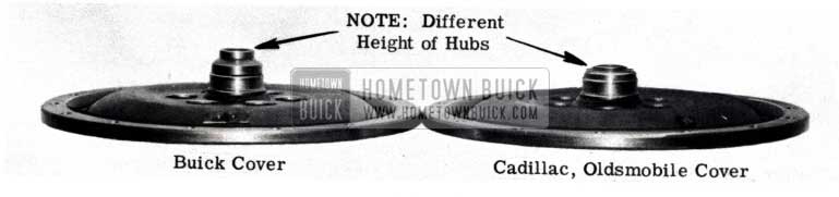
1953 Buick Dynaflow in Cadillac and Oldsmobile
The cover as used on both the Cadillac and Oldsmobile units has the same torque specifications and pump cover “0” ring seal as used on Buick. The difference is mainly in the hub height.
(2) CONVERTER PUMPCOVERPLUGANDMAIN SHAFT PILOT BEARING RETAINER BOLT, RETAINER AND BEARING.
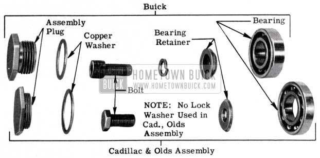
1953 Buick Converter Pump Cover Hub Assembly
Figure 43 is an exploded view of both the converter pump cover hub assembly as used in the Cadillac, Oldsmobile and Buick converter pump cover. As illustrated, the Cadillac, Oldsmobile parts are completely different from the Buick assembly with the exception of the copper washer which is completely interchangeable. This special hub assembly is used in both the Cadillac and Oldsmobile and is interchangeable between the two. IMPORTANT: There is NOT a LOCKWASHER under the main shaft pilot bearing retainer bolt as there is in the Buick assembly. (See Fig. 43)
(3) TWIN TURBINE ASSEMBLY (On Cadillac it is different)
All Dynaflow transmissions built for Cadillac will have the following Twin Turbine assembly. These gears are NOT interchangeable with the Buick or Oldsmobile units which have the same Twin Turbine Assembly. The Cadillac gears will NOT mesh into the gears of a Buick, Oldsmobile assembly and vice versa. Service procedures for the Cadillac Twin Turbine assembly are the same as those for Buick and Oldsmobile. The following Cadillac Twin Turbine gear WILL BE AVAILABLE through, and may be ordered from Buick Parts Warehouses:
Gr. 4.125-1163704 Sun gear
Gr. 4.125-1391742 Kit – Pinion
Gr. 4.126-1163709 Carrier
Gr. 4.126-1163707 Turbine
Gr. 4.126-1163710 Disc & Hub
(4) BELL HOUSING
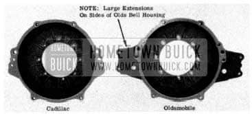
1953 Buick Dynaflow Bell Housing
Figure 44 illustrates the Cadillac and Oldsmobile transmission bell housing. These housings are only about one half (1/2) the length of the Buick housing. They can be readily identified as shown in Fig. 44
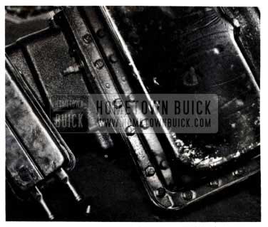
(5) TRANSMISSION CASE OIL PAN ASSEMBLY
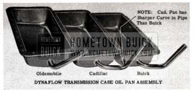
1953 Buick Dynaflow Transmission Case
As shown in Figure 45, the only difference in the Cadillac, Oldsmobile and Buick Dynaflow oil pan is the oil pan lower pipe. Buick and Cadillac are almost the same while Oldsmobile is more easily identified. The standard Buick Dynaflow transmission case oil pan gasket will also fit the Cadillac and Oldsmobile pans.
(6) REAR BEARING RETAINER
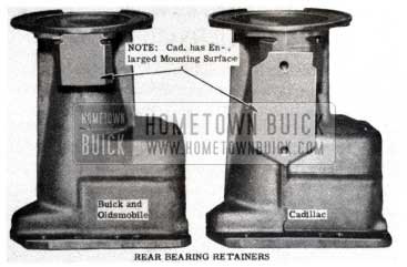
1953 Buick Dynaflow Rear Bearing Retainer
Figure 46 illustrates the rear bearing retainer as used on Cadillac, Buick and Oldsmobile. Oldsmobile uses the same rear bearing retainer as used on the 1953 Series 50 and 70 Buick. However, due to different mountings, Cadillac uses their own rear bearing retainers. Because of the differences in the drive shafts between Buick and Cadillac, and Oldsmobile there will be no universal joint and torque ball assembly on these units. In place of the universal joint to planetary shaft bolt, Cadillac and Oldsmobile merely use a plug (output shaft).
It should also be noted that both Cadillac and Oldsmobile have their own control arm and connecting linkage which are different from Buick. Barring the above listed parts, all Cadillac and Oldsmobile Dynaflow transmissions will be the same as the present 1953 Buick Series 50 and 70 Twin Turbine unit, using the same torque specifications, capacity and service procedures.
DYNAFLOW HIGH CLUTCH CHECK VALVE CHANGE
ALL SERIES
To reduce the possibility of Dynaflow transmission failure due to foreign material collecting under the ball check, the following change has been made in production. The High Clutch Piston Assembly (Gr. 4.166 No. 1343578) with Ball Bleed Valve has been replaced by a new High Clutch Piston (Gr.
4.166 No. 1162546) without Ball Bleed Valve. The High and Low Brake Drum (Gr. 4.169 No. 1393928) without Ball Bleed Valve has been replaced by a new High and Low Brake Drum Assembly (Gr. 4.169 No. 1391677) with a Ball Bleed Valve. (See Fig.47)
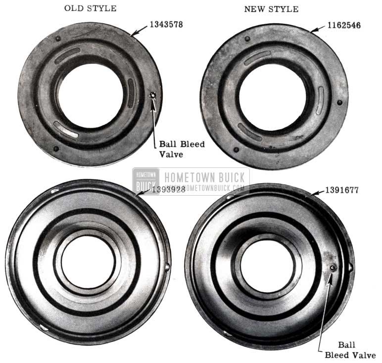
1953 Buick Ball Bleed Valve
The old style high clutch piston CAN NOT be used with the new style high and low brake drum. The old style high and low brake drum CAN NOT be used with the new style high clutch piston. There can be no interchanging of old and new style parts. Old style high clutch pistons and high and low brake drums are available to service for individual replacement of old style parts.
The new type piston and drum may be used together in any transmission.
TWIN TURBINE CONVERTER
ALL SERIES
Because of inquiries to the Service and Parts Departments, it is felt that there is some confusion on the use of the discontinued thrust washer as shown in Figure 48.
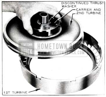
1953 Buick Twin Turbine Converter
This thrust washer was discontinued before production of the new Twin Turbine was started and therefore was never used in service. By redesigning the hub and disk assembly, the need for this thrust washer on the carrier was eliminated. This point was brought out and explained in the 1953 Buick Product School.
Because of inquiries for the washer we wish to again draw your attention to the fact that this thrust washer was never used in production or service, and is not necessary.
TWIN TURBINE WHINE
A slight twin turbine Dynaflow whine noticed while accelerating from approximately 15 to 30 M.P.H. is considered normal. In a few cases the whine is above the normal noise level and therefore is objectionable to an owner. Correction for abnormal noise can be made by replacing the planet pinions and sun gear with Group No. 4.125 Part No. 1391845, Sun Gear, Yoke and Planet Pinion Kit. (Fig. 49)
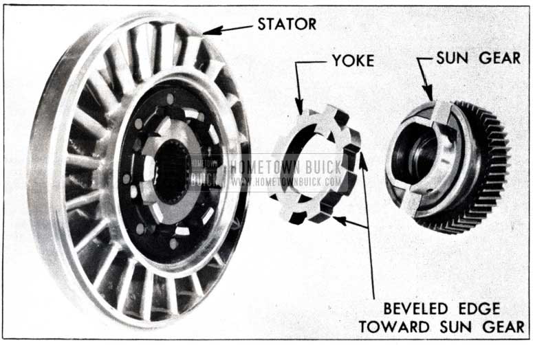
1953 Buick Dynaflow Turbine Stator
This is not to be considered a campaign, but to be used only in handling owner complaints on transmissions which are above standard noise level.
This kit incorporates a yoke between the sun gear and stator that in operation allows the sun gear to better center itself with relation to the planet gears, thus eliminating the whine.
This parts installation is made in the same manner as when replacing the old type sun gear and planet pinions. When installing the new parts, be sure that the bevel on the face of the yoke is assembled toward the sun gear.
Parts and labor will be accepted at straight AFA rates. Installation time is established at 5.8 hours. AFA’s on this installation to handle owner complaints will be accepted in the Zone offices through June 1, 1954. After that date, any installations made must be cleared beforehand with the Zone Service Manager.
LOCATION OF OIL LEAKS IN ENGINE AND DYNAFLOW
An examination and thorough test of the Dynaflow front pumps which have been returned as defective and/or leaking, has shown that many of these pumps function properly and do not leak .Many cases where the pumps do leak, it is only the seal that failed and this part only should be replaced, not the complete pump.
In order to eliminate the needless replacement of parts, a thorough check for the CAUSE of the oil leak is suggested. In some cases the front pump had been replaced because of oil leaking from the bell housing area, and continued to leak after repair. Further checking pointed out the leaks originated from the rear of the engine at the lifter gallery plugs, the main oil gallery plug, or from the rear main bearing.
To aid in determining exactly where the oil leak originates, our Engineering Department recommends that an oil dye be used in the engine oil to pin-point the leak.
You may order the dye, “Oil Red OS” in one pound cans at $4 a pound FOB Detroit, directly from the Eaton Chemical and Dyestuff Company, 1490 Franklin St., Detroit 7, Michigan. (See Page 1)
This is a perfectly harmless dye when used in either motor oil or Dynaflow oil. One teaspoon of the dye powder should be pre-mixed with approximately one-half pint of oil and then installed in either unit being tested. Subsequent operation of the car should then indicate the source of the leak.
CONVERTER PUMP LEAKAGE TEST
ALL SERIES 1953 TWIN TURBINE DYNAFLOW
Because of the design of the new 1953 Twin Turbine Dynaflow converter pump, section d, under paragraph 4-30, page 210, of the 1952 Buick Shop manual is superceeded by the following. As stated, these instructions apply only to the 1953 Twin Turbine Dynaflow. The instructions, as given in the 1952 Shop Manual are still recommended procedure when testing earlier model Dynaflow converters.
TESTING CONYER TER PUMP for OIL LEAKAGE
- Prepare a plate with rubber washer to close the opening in converter pump hub, as shown in Figure 50.
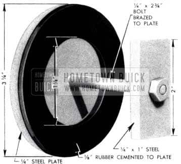
1953 Buick Dynaflow Steel Plate
The bolt head should be connected to the plate to seal the bolt hole, and the 1/8″ thick rubber washer should be cemented to the plate.
1953 Buick Dynaflow Drain Plug
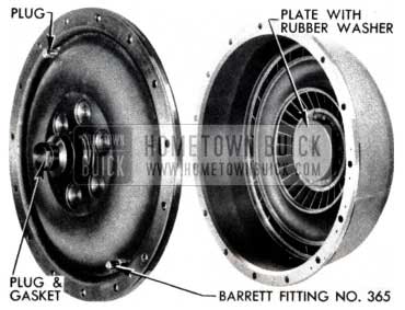
1953 Buick Dynaflow Plate with Rubber Washer
CAUTION: After a pump cover seal is used in this test it should not be used when rebuilding transmission.
NEW OIL COOLER & REAR BEARING RETAINER SCREW
ALL DYNAFLOW JOBS
1953 Buick Dynaflow Transmission Oil Cooler Screw
Figure 53 illustrates a new type of Dynaflow transmission oil cooler screw that will be used in conjunction with a new oil cooler. With the use of this screw, it will be unnecessary to disturb the two lower bolts holding the Dynaflow transmission rear bearing retainer to the transmission when installing a new oil cooler or performing service operations where it is necessary to remove or disconnect the oil cooler from the transmission. (See Fig. 54)
1953 Buick Remove Dynaflow Transmission Oil Cooler
NEW DYNAFLOW OIL GUAGE ROD
1953 V-8 ENGINE DYNAFLOWS
Due to production changes and to eliminate the possibility of using the wrong oil gauge rods in the straight and V-8 Dynaflow units, a new style Dynaflow transmission oil gauge rod (Gr. 4.133 No. 1163962) and filler pipe (Gr. 4.132 No. 1163963) for the V-8 engine will be used in production.
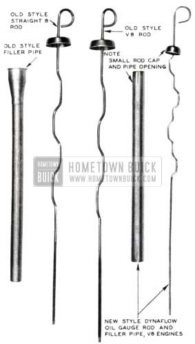
1953 Buick Dynaflow Transmission Oil Gauge Rod
As shown in Fig. 55, the new style filler pipe has a smaller opening on top with the resulting smaller cover cap on the new oil gauge rod. The overall length of the new filler pipe and oil gauge rod is shorter than the first product type. Therefore, none of the new and old parts are interchangeable.
The straight 8 oil gauge rod (Gr4.133No. 1339339) and fill pipe will remain the same.
PROPELLER SHAFT OIL SEAL
A new type oil seal (Group 5.449, Part No. 1346034 or 1346883) is now being used in the front of the torque tube to seal off the rear bearing retainer. This change affects all 1953 jobs but is not applicable and will not fit any models before 1953. This design eliminates the present universal joint oil seal and propeller shaft spline seal. The new seal is pressed into the front flange of the torque tube with the lip edge of the seal to the front of the car (See Figure 56).
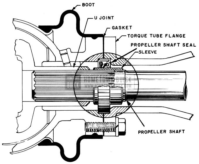
1953 Buick Dynaflow Propeller Shaft Oil Seal
The lip then rides on a sleeve which is pressed on the stub of the propeller shaft and closes off the spline from oil leakage. This seal also acts as a pilot between the torque tube and torque ball. The old cork gasket for the flange joint is replaced by a paper flange gasket. The installation of the seal can be easily made with hand tools.
Caution is necessary in installation of propeller shaft to prevent damage to the oil seal. Sharp impacts or heavy side pressures on the propeller shaft stub may crush the seal or cause it to pop out of place.
The pinion and propeller shaft assembly may be removed and replaced in service without disconnecting the third member housing from the torque ball. Start the propeller shaft stub in through the seal gently. Once the propeller shaft is properly centered in the third member housing, the remainder of the installation is as before. It is recommended that the pinion be pressed rather than driven into the carrier. The Service Department is developing a tool which will both pull out and press in the pinion with minimum harm to carrier bearings. This tool, when completed, will be announced in a future B. P. S.
The new parts resulting from the 1953 body and transmission changes in Series 40, 50, and 70 are:
Universal Joint – Group 5.548 No. 5665605 – Shorter rear yoke
Torque Ball – Group 5.564 – No. 1346028 – Longer neck to flange, 4 holes
Boot- Group 5.565 – No. 1346201 – Larger
Torque Tubes – Group 5.505 – No. 1161553-40 – Shorter tube 1346062-50-70- (Except 52-72R) 1346513-52-72R
Propeller Shaft – Group 5.441 No. 1346053 – Shorter tube (Except 52-72R)
Oil Seal – Group 5.449 No. 1346034 / 1346883 (either seal may be used)
Gasket – Group 5.560 No. 1346036
DYNAFLOW SNAP FASTENER FAILURE
ALL 1953 DYNAFLOW EQUIPPED BUICKS
There have been a few reports where the snap fastener (Valve operating rod and clevis to valve operating lever) Gr. 4.268 No. 1340039 have fallen out. When this happens, the Dynaflow will operate only in that range that the valve operating rod was in when the snap fell out, regardless of the position the Dynaflow selector is moved to. It is recommended that when any 1953 Dynaflow transmissions are disassembled for repairs this fastener should be checked, and if it does not appear to fit properly and has apparently been reworked, it should be replaced. The reworked snap fastener may be identified by the ground diameter surfaces as illustrated in Figure 57.
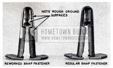
1953 Buick Dynaflow Snap Fastener
SYNCROMESH TRANSMISSION
SERIES 50
With the increase in horsepower of the new V-8 engines, it was necessary to use a heavy duty synchromesh transmission in the Series 50. Therefore, all Series 50 Buicks equipped with synchromesh will be using basically the same transmissions used in the 1948 Series 70 synchromesh with the following exceptions:
- Transmission main shaft.
- Transmission main drive gear.
- Transmission rear bearing retainer.
- Rear bearing retainer bushing.
- Transmission’s second and third shifter yoke.
Overhaul procedures are basically the same as those used in servicing the 1948 Series 70 jobs.
SYNCROMESH TRANSMISSION
The Synchromesh Transmission Assembly Group 4.003-1390131, which was used on the 1948-1949-1950-1951-1952 Series 40-50 (LHD), has been discontinued by the Parts Department since it went out of production at the end of 1952.
Due to the changed Universal Joint, Torque Ball, Torque Ball Boot and Speedometer Driving Worm, the 1953 Series 40 Transmission cannot be used interchangeably. If a complete transmission assembly is required for one of the above models, it will be necessary to build-up the transmission from the component parts, or the 19S3 Series 40 transmission Group 4.003-1391260 can be reworked as follows:
Remove:
1- 5.565 1346201 Boot-Torque Ball
1- 5.56 41346482 Ball-Universal Joint Torque
1- 5.54 81391164 Universal Joint
1- 4.34 38611567 Worm-Speedometer Driving
Add:
1- 5.565 1334298 Boot-Torque Ball
1- 5.564 1334366 Ball-Universal Joint Torque
1- 5.548 1393717 Universal Joint
1- 5.560 1312398 Seal-Universal Joint Oil
1- 4.343 1315449 Worm-Speedometer Driving
PARTS CHANGES
DYNAFLOW TRANSMISSION ASSEMBLIES
When present stocks of Group 4.003, Numbers 13904S8 and 13904S9 Dynaflow Transmission Assemblies are exhausted, they will be discontinued.
These transmissions were for use in 1948 and 1949 cars, and if, a transmission is required for one of these cars proceed as follows:
When a complete transmission is needed for a 1949 Series SO Dynaflow, then Group 4.003, Part 1390544 Transmission may be used by removing Oil Pan 1339296 and installing Group 4.195, Part 1338967 Oil Pan.
When a complete transm1ss1on is needed for a 1948-1949 Series 70 Dynaflow, then Group4.003, Part 1390S43 Transmission may be used by removing Oil Pan 1339296 and installing Group 4.195, Part 1338967 Oil Pan.
TRANSMISSION PART CHANGE
Due to a change in the rear axle design, which went into production approximately March 1, 19S3, the transmission assembly numbers were changed. This change in transmission numbers was due to the change made in the speedometer driving worm which is assembled into the transmission. To simplify the stocking of complete transmissions, only, the second type transmission will be stocked by the Parts Department. Therefore, when using one of the second type transmissions to replace a transmission in a first type job, it will be necessary to change the speedometer driving worm as follows or replace the old type.
4 .003 – 13909S3 Transmission Assembly
1953-40 Dynaflow 1st – Jobs
Replaced By:
4.003 – 1391258 Transmission Assembly
1953-40 Dynaflow After-Jobs
When using Transmission No. 1391258 in a 1953-40 D.F. 1st-Jobs, it will be necessary to remove 4.343-1343039 Worm-Speedo Driving (8T) and install 4.343-134045O Worm-Speedo Driving (7T).
4.003 – 1390936 Transmission Assembly
1953-50-70 Dynaflow 1st-Jobs
Replaced By:
4.003 – 1391253 Transmission Assembly
1953-50-70 Dynaflow After-Jobs
When using Transmission No. 1391253 in a 1953-50-70 1st-Jobs, it will be necessary to remove 4.343-1345168 Worm-Speedo Driving (8T) and install 4.343-1345071 Worm Speedo Driving (7T).
4.003 – 1391084 Transmission Assembly
1953-40 Synchromesh 1st Jobs
Replaced By:
4.003 – 1391260 Transmission Assembly
1953-40 Synchromesh After-Jobs
When using Transmission 1391260 in a 1953-40 Synchromesh 1st-Jobs, it will be necessary to remove 4.343-8611567 Worm-Speedo Driving (8T) and install 4.343-1315449 Worm-Speedo Driving (7T).
4.003 – 1391205 Transmission Assembly
1953-50 Synchromesh 1st Jobs
Replaced By:
4.003 – 1391259 Transmission Assembly
1953-50 Synchromesh After-Jobs
When using transmission 1391259 in a 1953-50 Synchromesh 1st-Jobs, it will be necessary to remove 4.343-8611567 Worm-Speedo Driving (8T) and install 4.343-1315449 Worm-Speedo Driving (7T).
REWORK OF C-WASHER FOR U-JOINT PULLER
Due to a past change in design of our transmission Universal joint, it will be necessary to rework the C-Washer that was furnished with the Kent-Moore Universal Joint Puller J -682A. The dotted line in Figure 58 illustrates the original design of the C-Washer.
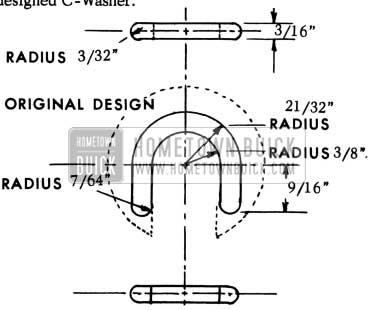
1953 Buick C-Washer for U-Joint Puller
To rework, grind off excess metal to conform approximately to the specifications as given in Fig. 58. All present and future shipments of U- joint pullers from Kent-Moore will have the newly designed C-Washer.
DISCONTINUED U JOINT TORQUE BALL BUSHINGS
ALL SERIES
The Universal Joint Torque Ball Bushings in Group 5.566 are being discontinued and will no longer be serviced individually by the Parts Department. In the future, when a Torque Ball Bushing fails, it will be necessary to install a new Universal Joint Torque Ball Group 5.564 to effect a repair.
This bushing is being discontinued on recommendation of the Engineering and Service Departments, since when installing the bushing, which was furnished with the I.D. semi-finished, it was necessary to machine the I.D. for the proper running clearance, and it was felt that the field was not equipped to do this machining. Numerous complaints were received that the bushings were not properly installed in the field, resulting in early failures.
For these reasons, it was felt that much more satisfactory service would be given if a new Torque Ball was installed when a bushing failed.
Rebuilding a ‘53 Skylark, looking for the propeller shaft seal. Grow. 5.449 no 1346034
Where can I find this seal??
Thank You
Gary Miano