1953 BUICK STEERING
RATIOS
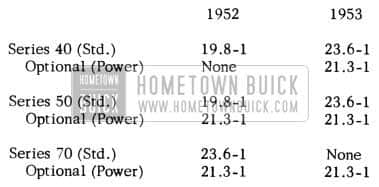
1953 Buick Steering Gear Ratios
LOWER CONTROL ARM AND SHAFT ASSEMBLIES
A change is being made by the Parts Department in the method of servicing the Lower Control Arm and Shaft Assemblies (“A” Frames) Group 6.168.
At the present time, these parts are serviced completely assembled as the right and left parts. In order to simplify stock and reduce inventory, the changed part can be used on either the right or left side. This new part will have the (2) two outer rivets omitted, and bolts, washers, and nuts will be included for use in place of rivets. By using these bolts and nuts, the bumper retainer can be installed with the stabilizer connection end on either side making the part adaptable for use on either the right or left side. The bolts and nuts should be torqued to 55 to 65 ft. lbs.
The following parts are affected by this change:
Group 6.168 – 1393398 to be replaced by 1391188
Group 6.168 – 1393399 to be replaced by 1391188
Parts 1393430 and 1 393431 will also be replaced by an interchangeable part when present stocks are exhausted.
The balance of parts in Group 6.168 will continue to be serviced as right and left assemblies.
VICKERS & SAGINAW POWER STEERING PUMPS
ALL 1953 POWER STEERING EQUIPPED JOBS
During the past year we have given specifications and information pertaining to the Vickers power steering pump. A few questions have been raised as to whether this information also pertained to the Vickers power steering pump built by Saginaw. The Saginaw built Vickers pump is the same as the
Vickers pump and, therefore, all specifications and information given in 1953 under the title of Vickers pump will pertain to the Saginaw built pump.
VICKERS POWER STEERING PUMP OPERATION
1953 SERIES 50-70
There have been requests from the field for information on the operation of the Vickers Pump as used in the 1953 Super and Roadmaster Buick equipped with power steering. All reference in the write-up will be made to Fig. 67 on Page 58.
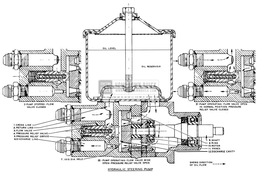
1953 Buick Hydraulic Steering Pump
The different pans have been numbered to facilitate their location. These numbers will be given in parentheses after the term as used in the write-up.
The Vickers Pump houses a slotted driving rotor in which twelve vanes (11) slide radially outward to contact the hardened and ground inside surface of a ring. As the shaft and rotor rotate, centrifugal force and fluid pressure against the inner ends cause the vanes to follow the cam contour of the ring, which is so shaped that two opposing pumping chambers are formed. In each pumping chamber the increasing and decreasing pockets formed between the rotor (10), vanes (11), and ring (9), propel the oil from the entrance to the exit ports of the pump.
The pump ring is designed so that the pump could deliver 4 gal. per. min. GPM at 1200RPM. There is actually no need for this amount of flow, so a flow valve (3) has been designed in the pump cover to permit a maximum of 1.8 gal. per min. GPM at 2000 RPM against 50 psi. lb. per sq. in. pressure. The minimum flow the pump must produce is .9 gal. per min. GPM at 465 RPM pump idle against 700 psi. To accomplish flow regulation the flow valve (3) is located with one end blocking a port from the discharge cavity (12) to a cross line (1) which leads back to the reservoir. There is a spring at the rear of the valve tending to force the valve to a position where the port will be closed. (See Roman Numeral I) The pressure in the discharge cavity is pushing against the front area of the valve tending to force it open. Leading from the discharge line in the cover to the cavity behind the valve, there is a small orifice (5) which allows pressure to build up behind the valve and force it closed. As a result the valve action depends on the pressure differential on the front and rear of the valve against the force of the spring. As long as there is any flow of oil through the pump, the pressure in the discharge cavity (12) against the front of the valve will always be greater than the pressure at the rear. This is because all oil from the cavity must pass through a .1015 diameter hole (7) to the discharge line (6) and back pressure is created in the discharge cavity (12) greater than the pressure in the discharge line (6) The back pressure tends to open the valve against the spring load of approximately 6.5 lbs. when in the closed position. Under operating conditions the flow valve (3) startstoopenat300-400RPMof the pump. As a result, the flow valve is working when the pump idles at 465 RPM. (Engine idle 450 RPM)
When the steering wheel is turned as it would be against a curb or wheel turn stop so that the steering valve closes off the oil flow and the pump continues to run, pressure will build up rapidly. To keep from obtaining excessive pressures in the system, a pressure relief ball check valve (4) is incorporated in the flow valve. A ball check in the valve is seated by a spring of approximately 16 lbs. load and prevents oil in the cavity behind the flow valve from seeping past the ball seat, down the center of the valve and into the cross line (1) which leads into the reservoir of the pump. The setting of this ball check valve is 750-900 psi and is adjustable by means of shims between the screw at the rear end of the valve (not shown) which contains the valve seat and the valve body. When the pressure exceeds these limits, the force on the ball check overcomes the force of the spring and opens. This relieves the pressure behind the valve tending to force it closed and since the force on the front of the valve tending to open it is much greater than the spring force tending to close it, the valve completely opens and the pump dumps most of the oil through the cross line. (1) The oil continues to dump until the pressure the pump is working against drops below the relief valve (4) setting and then the ball again seats and the flow valve is able to resume operating.
1953 POWER STEERING GEAR
Extreme care must be exercised, when servicing power steering gears, to use the correct parts. The following parts are new for 1953 and cannot be interchanged with corresponding 1952 parts:
- Housing and valve cover. Due to piloting the valve, and new O-ring seals each side of the valve.
- Valve assembly. Due to new groove spacing, new plungers and springs, new location of check valve.
- Pitman shaft gear (50 -70). This shaft is longer.
- Shaft assembly, ball nut and contact. This assembly is new due either to changed shaft length or new horn contact location or both. The steering shaft is also ground to a closer tolerance at the upper bearing surface.
- Pressure and return hoses. Pressure hose 50-70 is new due to increased length. It is longer than 40 series. All return hoses are new due either to increased length or a new fitting at the pump end or both. 40 series return hose is shorter than the 50-70.
We have had a few instances where jobs equipped with power steering failed to return satisfactorily after cornering.
If this condition is encountered, we suggest that a check be made of the following:
- Tightness of king pin in their bushings.
- Heavy adjustment of steering gear and steering linkage.
- Tight steering shaft upper bushing.
- Loose worm thrust bearings. This will also at times cause a snapping noise in the gear.
- Thrust bearings reversed in assembly.
- Wrong O-ring seals each side of valve. One case of 1952 O-rings installed in a 1953 car caused excessively light steering effort and no reversibility.
- Improperly machined grooves in the valve spool or valve housing. This requires changing the valve assembly.
- Tip interference of the center tooth of the pitman shaft gear with the mating tooth on the ball nut. This will be evident, when lashing the gear, as the preload approximately 120 degree offcenter will be higher than on center. This may occur either right or left of center. If this condition exists, it will be necessary to install a new pitman shaft gear.
POWER STEERING PUMP LEAKS
1953 VICKERS PUMP
Due to some leakage at the plug located at the rear of the 1953 Vickers Pump, we are releasing a new O-ring seal, Gr. b.b22, No. 5680711 to replace O-ring, 5665829. This new ring is .487 mean I.D. with .103 cross section diameter as compared to .424 mean I.D. with .103 cross section diameter of the present O-ring. This change has the effect of increasing the amount of squeeze and reducing the stretch of the O-ring in the assembly.
The assembly of this O-ring is critical and will result in a damaged seal if not done properly. When making this assembly, it is recommended that the following procedure be used.
- Remove all burrs from around the snap ring groove and the chamfer with a fine stone.
- Apply lubricant to O-ring seal and in snap ring groove.
- Assemble plug and O-ring to pump cover flow control valve bore from the chamfer (Rear) end until end of plug is just past snap ring groove.
- Insert snap ring.
Any attempt to assemble plug from the other end to eliminate removing snap ring will result in cutting the O-ring on the sharp edges of the cross hole.
POWER STEERING PUMP SEAL
VICKERS PUMPS
Certain reports indicate that the Hydraulic steering gear oil pump shaft seal (Gr. 6.617 No. 5665833) is being installed backwards when servicing the pump in the field.
The following procedure should be followed for correct seal installation as directed by the Buick Power Steering Service Training Manual (Page 62)’ and the 1952 Buick Shop Manual (Page 7-26, Section C, Paragraph 3).
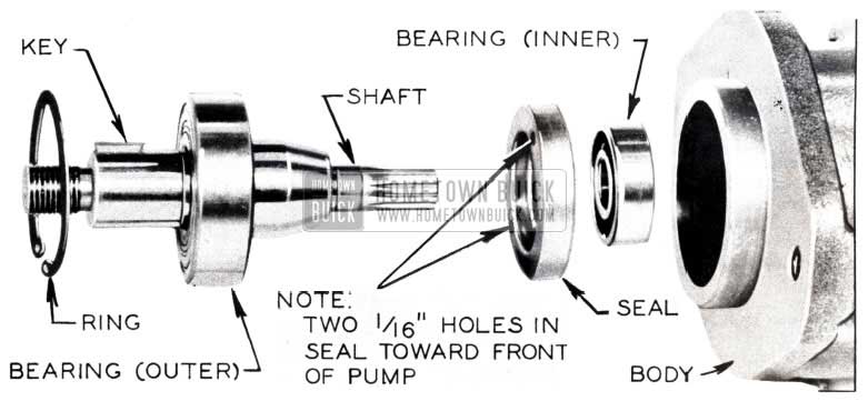
“Make certain that the bearings and shaft seal are firmly seated in their proper positions. After the inner ball bearing is installed, the shaft seal must be installed with the two 1/16″ holes in the seal casing toward the front or outside of the pump (pulley end). Use a tube or shaft 1 3/4 in diameter to apply pressure against outer edge of seal during installation.” (See Figure 68)
1953 Buick Power Steering Pump Seal
HYDRAULIC STEERING PUMP SHAFT SEAL INSTALLATION
Due to the number of hydraulic steering pump front shaft seals that have been replaced in the field, it is felt that the following information should be read carefully in an attempt to alleviate future steering pump failure.
The pump shaft seal used in the power steering pump is a special seal designed to prevent leakage of oil and also to prevent air from entering while the pump is operating. When assembled into the pump, the seal lip hugs the shaft with a predetermined pressure. This pressure is determined by a small spring on the inside of the seal which presses on the rubber element. As the lip wears, this same spring causes the rubber element to move out enough to take up for the wear.
While the pump is running, there is a vacuum on the inside of the pump. This means that there is a pressure on the outside of the seal. There are two small holes in the seal case which communicate with the back of the seal lip. The pressure that exists on the seal presses on the seal element through these two holes, which in effect increases the sealing pressure on the shaft.
SEAL IDENTIFICATION
The pressure side of the seal can be identified by two small holes in the seal case.
SEAL PROTECTION
All of the oil seals are shipped with a protector sleeve inserted in the inner periphery of the seal. This sleeve is installed at the factory to prevent the action of the spring from pushing the rubber element out of the case and therefore should be left in place until the seal is assembled into the pump
INSTALLATION PROCEDURE
Clean the casting and remove any burrs in the seal bore that may have been raised during disassembly of the old seal.
Remove protector sleeve from the seal, dip the seal in automatic transmission fluid.
Use a tube or shaft 1 1/4″ in diameter to apply pressure against the outer edge of the seal during installation. (Refer to “Power Steering Pump Seal,” Page 60 of this Edition and “Assembly of Vickers Pump,” Sub Paragraph C, Gr. 7-6, Page 165 of the 1953 Buick Shop Manual for more information of this assembly)
Immediately install bearing and shaft assembly. Care should be used to avoid damage to the seal lip by the splined end of the shaft hitting the seal. In event that the shaft cannot be assembled immediately, the protector sleeve should be inserted into the seal with the rounded end of the sleeve toward the inside of the pump.
At present a special tool is being designed to facilitate the installation of this seal. It is MOST important that the greatest care be taken in marking this seal installation and that all possible means are used to prevent damage to the seal at that time. A future BPS will carry information on when this special seal installation tool will be available.
STEERING SHAFT BEARING
POWER STEERING ONLY
Reports indicate that the steering shaft upper bearing (Gr. 6.521, No. 5663863) released for the 1952 power steering jobs is being used in 1953 models. Due to a difference in the outside diameter of the 1953 steering shafts and the inside diameter of the 1952 bearing, the 1952 bearing will not properly secure the 1953 steering shaft and may cause a rattle and slight shaft looseness.
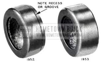
The 1953 bearing (gr. 6.521, No. 5664839) must be used when repairing any of the 1953 power steering jobs. Figure 69 illustrates the best identifying characteristics of the two bearings.
1953 Buick Steering Shaft Bearing
It is suggested that the local dealer Parts Departments be informed of this situation in order to avoid giving out the improper bearing.
POWER STEERING GEAR VENT LEAK
1953 SERIES 50 &70
There has been some trouble on power steering cars with grease leaks at the vent plug. It is felt that some of this may be due to overfilling the housing during regular 1000 mile Lubricare checks so that when the gear is turned, the grease is displaced out the vent.
In order to minimize this difficulty, the power steering gear housings should be filled with the gear turned to full left turn position. At this point the rod on the power piston is pro jeering into the housing as far as possible. Then as the gear is turned, the rod is drawn out of the housing into the power cylinder leaving more space for the grease.
There are other factors such as temperature change and oil seal leaks involved in grease leaks at the vent plug, but it is felt that taking the above precaution will be an improvement and possibly eliminate some of these leaks.
STEERING LINKAGE SQUEAK
1953 SERIES 50 & 70
The field has reported that a hard squeak is sometimes heard, under normal driving conditions, from the front steering assemblies. This condition has been traced to the cotter pin, that secures the adjusting nut to the intermediate tube, striking the left hand tie rod assembly when the cotter pin is in an unfavorable position. (See Figure 70)
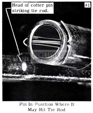
1953 Buick Steering Linkage Cotter Pin
If this condition occurs, it is suggested that the cotter pin be reassembled so that the head of the pin will be on the side of the tube away from the tie rod. (See Figure 71)
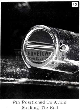
1953 Buick Steering Linkage Cotter Pin Positioned
If it is not possible to bend the legs of the cotter pin flush with the intermediate tube, thereby obtaining proper clearance, the adjusting nut should be TIGHTENED l/4 turn and the cotter pin installed as shown in Figure 72.
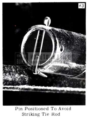
1953 Buick Steering Linkage Cotter Pin Correct
Lubricare men should be informed of this condition so that it may be observed and corrected if causing trouble.
LOWERED STEERING WHEEL
SERIES 50-70
There have been requests for information on the parts and procedure used to lower the steering wheel height on the 1953 Series 50 & 70.
Following is the suggested procedure:
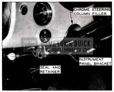
Disconnect steering gear at bracket on instrument panel and remove seal and retainer on steering gear at toe board (See Figure 73).
1953 Buick Lower Steering Wheel
Disconnect the vertical transmission shift rod. Loosen bolts that hold gear to frame enough to move gear down to desired height. (1 1/2” is max. at steering wheel)
To move the steering wheel down, it is necessary to use a spacer or spacers at the instrument panel bracket. Spacers may be used in any combination up to the limited thickness of (NOTE: 1/4” at instrument panel is approximately 1 1/2” at wheel.) They are available in two sizes, 3/16” thick (Gr. 6.764 No. 1332163) and 3/4” thick (Gr. 6.764 No. 1341693).
If the maximum steering wheel drop is made (1 1/2”), in addition to the use of one 3/4” spacer, a different upper transmission shift rod (Gr. 4.040 No. 1161938), which is 13″ long, must be used. This is the same rod as that used on the 1953 76 X Skylark. Any steering wheel height change may require minor adjustments of the lower shaft rod to keep the Dynaflow selector indicator lined up with the indicator letters (Refer to 1952 Buick Shop Manual, Page 4-56, Section 4-26).
In order to cover the excess space present between the steering shaft mask jacket and the instrument panel after lowering the steering column the full B2″, a chrome steering column trim filler (Gr. 9.738, No. 1161927) may be used as illustrated in Figure 73. This filler is standard equipment on all Skylark jobs.
When desired wheel position is obtained tighten steering gear to frame and instrument panel and make sure rods are properly cotter pinned and clevis jam nut tightened, and reposition the steering gear seal and retainer at the toe board.
Then with everything hooked up check toe -in on front wheels and correct if necessary to 1/16 to 1/8.
Leave A Comment
You must be logged in to post a comment.