GENERAL SPECIFICATIONS
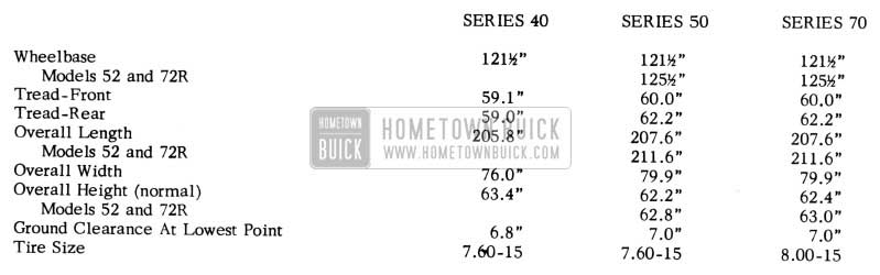
1953 Buick Body Specifications
1953 COLOR CHART
ALL SERIES
In order to simplify the ordering of Duco Paints, DuPont has set up a new paint ordering code number system. It is suggested that when purchasing or ordering any Duco Paints that the new paint order numbers given in the following chart be used.
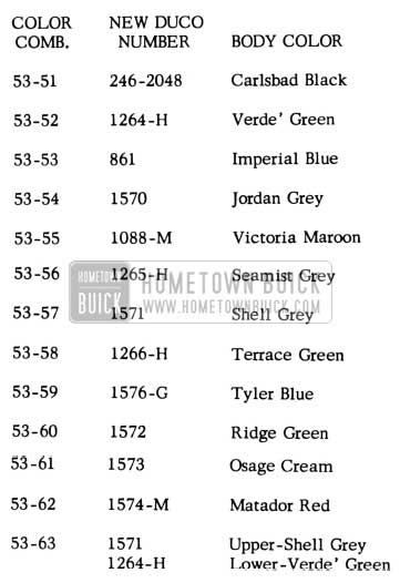
1953 Buick Color Chart
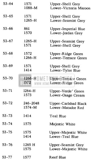
1953 Buick Paint Combinations
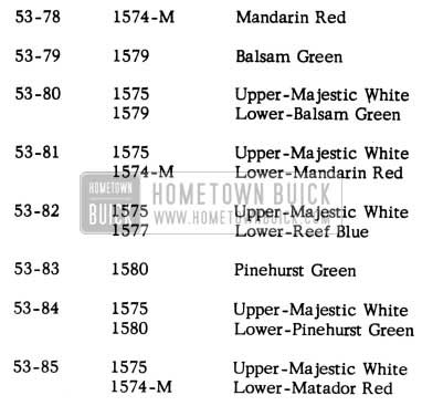
1953 Buick Paint Colors
1953 TRIM CHART
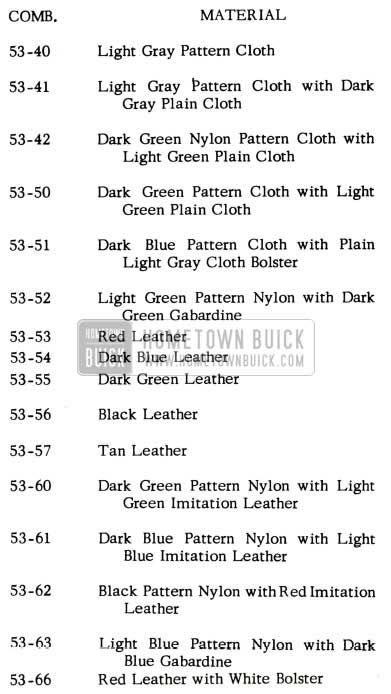
1953 Buick Trim Chart
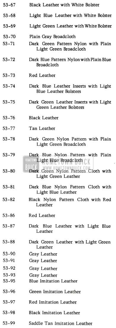
1953 Buick Trim Combinations
INSTRUMENT PANEL COLORS
1953
DI-NOC TRANSFERS
70 SERIES – ALL STYLES
The lower sections of the instrument panels and front door finishing panels on the Roadmaster Series are decorated with a Di-Noc transfer finish designed with a distinctive Buick pattern for beauty and individuality. Di-Noc transfers are flexible sheets of lacquer film and are applied to lacquer painted surfaces with a special cementing solution. The new transfers make possible a decorative effect not possible with sprayed lacquers. They are furnished in red, green, blue and gray colors to harmonize with the new interior trim and paint colors.
The transfer, when ordered for service comes in a sheet 24″ x 37 ” and therefore must be cut to size desired. The sheet is ordered under Group 10.232, part number per color desired:
White checks – No. 462 7550
Red checks – No. 462 7551
Blue checks – No. 4627552
Green checks – No. 4627553
Tan checks- No. 462 7554
The following procedure may be used to refinish Di-Noc transfers on 1953 Buick Roadmaster instrument and door finishing panels:
Perform preparation operations as follows:
Door Finishing Panels – Remove from body and apply transfer as a bench operation. Mask off painted surfaces.
Glove Compartment Door – Remove from body and apply transfer as a bench operation.
Instrument Panel- Remove or loosen instrument panel parts as required to facilitate transfer application operations. Mask off adjacent paint, glass, hardware and trim parts. Remove or protect floor covering.
- Clean finish with wax and grease remover such as “Pre-Kleano”, “Prep-Sol” or equivalent.
- Sand damaged finish and featheredge as required.
- If bare metal is exposed, apply metal conditioner such as “Metal-Prep”, “Deoxidine “, or equivalent. Allow to dry and then apply primer.
- Apply surfacer or primer surfacer as required and allow to dry.
- Apply putty glaze as required and allow to dry.
- Dry sand surface smooth with No. 320 sandpaper.
- Apply a good, wet coat of clear lacquer, allow to dry and wet sand lightly with No. 320 sandpaper and water.
- Select transfer to match repair area.
- Transfers which appear “brittle” may be made more flexible by spraying” back or painted side” with clear lacquer. If this operation is performed, allow transfer to air dry at least 20 minutes before using.
- Rough trim transfer allowing 1/2 inch of extra material around all sides.
- Place transfer in water of room temperature to loosen paper backing.
- Wet surface to be refinished with water and position transfer. Remove paper backing from transfer.
- Wash transfer with sponge and water to remove paper adhesive.
- Check transfer alignment and squeegee into place as follows:
- Always start at center and squeegee toward ends. Use over-lapping strokes to remove all air bubbles and wrinkles. Position transfer by hand as operations progress to eliminate wrinkles and to maintain alignment.
- Use plain water as a lubricant for squeegee operation.
- When applying transfers to extremely contoured surfaces, first secure transfer to flat surfaces around contoured surfaces and then stretch transfer to desired position.
- Use sponge and “hot” water to stretch and secure transfer to contoured surfaces. The water should not be “hotter” than one’s hands can safely stand. Although hot water causes transfers to stretch more readily, perform this operation gradually and with extreme care to prevent tearing the transfer.
- Peel back half of transfer and apply the Di-Noc Welding Solution. This is handled by Buick and can be ordered under Group 10.232, No. 1391499, solution, Di-Noc Welding – for transfer. This is a 1/2 pt. can concentrated.
CAUTION: Use care to prepare welding solution according to directions of manufacturer.
- Secure transfer into place as in step 14.
- Peel back other half of transfer, apply welding solution and secure transfer into place.
- Wash transfer with water, trim off excess edges with sharp razor blade and allow to dry.
- Apply two (2) good coats of clear pyroxylin lacquer and allow to dry.
- Oil sand finish with No. 400 sandpaper and oleum spirits or equivalent.
- Remove masking tape at solid color breaklines.
- Rub out and polish by hand. Use hand rubbing compound. Do not machine polish.
The following items are suggested as aids in the application of Di-Noc transfers:
For best results, transfers should be applied at normal room temperatures.
Drying times can be speeded up through the proper use of heat lamps.
Apply welding solution during transfer application operations as required, particularly at the edges. Welding solution is sometimes washed out when using “hot” water during “stretching” operation.
NEW PAINT
GLACIER BLUE
This is to advise that effective on or about May l, 1953 we are discontinuing the following color combinations:
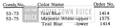
1953 Buick New Paint
To supplement this discontinued color and combination, a new color and color combination has been approved and will be available at or about the same time the above mentioned color and combination is discontinued. The new color and combination is as follows:
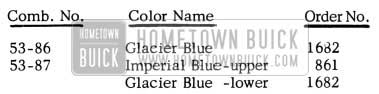
1953 Buick New Colors
Both the new color and combination will carry the option of Matador Red Wheel color as requested. Glacier Blue is considerably lighter than Tyler Blue (1576) and has a powder blue cast with no metallic content.
APACHE RED & MATADOR RED PAINT SPOTTING
A few complaints from scattered sources across the country have been received to the effect that the above colors tend to develop dark stain spots varying in color from light tan to almost black. They vary in size from specks up to 6 inches in diameter at times.
Investigation has revealed that this discoloration is a phenomena of the cadmium pigment which has to be used in this type of paint. Exposure to sunlight and moisture and certain industrial atmospheric conditions, when this pigment is placed on metals containing iron, such as steel, seem to be the things which may cause this condition. Actually the number of complaints received in relation to the number of cars finished in these colors has been minor:
Further investigation has revealed that most of these spots can be removed by polishing. Refinishing is not recommended unless an unusually server case is encountered because excessive polishing will reduce the paint film thickness.
MAROON PAINT “CROCKING”
ALL SERIES
A few cases have been reported where the maroon paint used on the Door Finishing Panels (interior) has “crocked” and caused stains on the owner’s clothing.
The condition can be corrected by applying clear lacquer seal coats on these panels (interior) as outlined below:
- Remove any dead pigment by compounding with Duco Rubbing Compound or its equivalent.
- Sand panel lightly with No. 500 grit paper.
- Apply two (2) or three (3) light coats of DuPont No. 1234 clear lacquer.
- Hand polish surface to obtain desired finish.
PAINT STAINING FROM MASKING TAPE
ALL STYLES
A few inquiries have been received concerning the staining of paint upon contact with masking tape, particularly on lighter colors. The following information is furnished to help you understand the causes and the remedy for this condition, although it is not a prevalent complaint.
Stains are basically caused by a chemical reaction between the paint and some ingredient in the tape, masking paper or other material. The stains are usually brownish in color and cannot be removed by ordinary means.
The severity of stains on LACQUER FINISHES is governed by the following conditions:
- Length of time exposed to sunlight or other ultraviolet light.
- Length of time the tape remains on the finish. Stains on lacquer finishes develop very slowly, often several days after the tape has been removed.
The severity of stains on ENAMEL FINISHES is governed by the following conditions:
- State of “cure” of enamel – more severe on undercured finish.
- Length of time the tape is exposed to higher range baking temperatures.
- Length of time the tape remains on the finish. Stains on enamel finishes develop immediately, or very soon, after tape has been removed.
As a possible solution to a tape staining problem the following changes should be made, wherever possible:
- Reduce the length of time that the tape remains on the finish (lacquer or enamel).
- On lacquer finishes, reduce the length of time the tape is exposed to sunlight or other ultraviolet lights.
- On enamel finishes, reduce the length of time the tape is exposed to higher range baking temperatures.
- Also on enamel finishes, make sure that the finish is properly cured.
The tape manufacturers recognize this problem and are working to overcome it.
HOOD ALIGNMENT
ALL SERIES
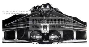
It has been decided to replace the standard nuts and lock washers on the front hood reinforcement bars with five self-locking 1/4 -20 nuts.(See Fig. 133)
1953 Buick Hood Alignment
These nuts will eliminate the loosening of the reinforcement members which was caused by the twisting of the hood on raising.
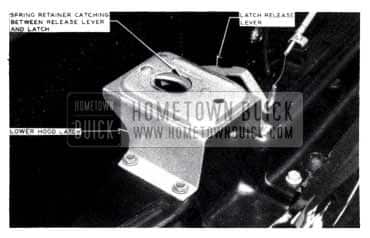
In the field, the lower hood latch (See Fig. 134) is being shifted to one side or the other as an aid in aligning hoods.
1953 Buick Hood Release Lever
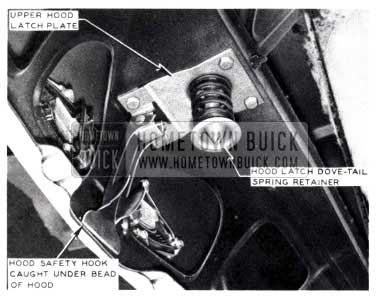
In some cases, the hood latch dove tail spring retainer (See Fig. 135) has caught under the edge of the latch release lever (See Fig. 134) due to this side adjustment of the lower latch. This condition will result in either being unable to pull hood release lever or raise the hood past the “safety” position.
It is cautioned that a minimum of hood aligning be done by moving either the lower hood latch or the upper hood latch plate.
It has been reported that occasionally a hood safety hook will catch in the open or released position under the bead of the hood as illustrated in Fig. 135.
1953 Buick Hood Latch Dove-Tail Spring Retainer
When this condition exists, tap lightly with a hammer, on the bead of the hood until the safety hook releases freely.
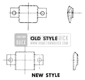
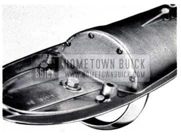
1953 Buick Hood Guide Roller Pad
Figure 136 is an illustration of the new Hood Guide Roller Pad, Gr. 8.019, No. 1162993 which replaces the old No. 560361. This new roller pad is now available to the field. The new roller pad, as compared to the discontinued one, has a flatter, less curved surface and affords much smoother hood raising action. The new roller pad eliminates the tendency of the hood to “squat” or hesitate in the center when it is raised. It is suggested that the new roller pad be placed on all jobs where any difficulty of this type is encountered.
Hood adjustment can be made by changing the position of the hood springs giving different fit and raising qualities.
1953 Buick Remove Front Seat Side Panel Kick Pads
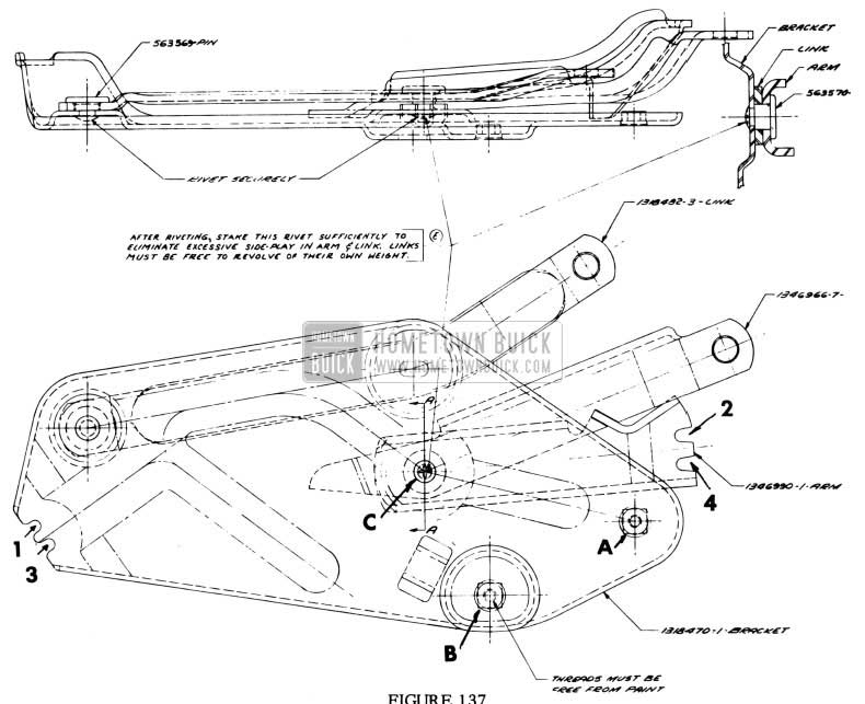
Fig. 137 is a drawing of the 1953 hood hinge. Each hood spring notch has been numbered. Following are combinations of hood spring positions that may be used to achieve various effects of hood position and raising.
If the hood spring is attached to position:
1 and 2, the hood spring will pass directly over dead center of the hinge and will afford the easiest raising of the hood. However, this hood spring position will give a minimum of “pull down” on a closed hood.
2 and 3, it affords substantial “pull down” qualities and easy hood raising. The hood spring is set in this position in production.
1 and 4, there is greater hood “pull down” than any of the previously mentioned positions but also causes the hood to lift hard.
3 and 4, it offers the maximum “pull down” of the hood, but a minimum of hood raising assistance. This position is not recommended as it requires extreme pressure to lift the hood.
It is suggested that a combination of these spring positions may be used to afford the required conditions of hood fit and operation.
In some cases it will be necessary to reposition the hood hinges in order to properly align the hood. Following is a suggested procedure:
- Remove both hood springs as directed in the article entitled “Hood Spring Removing and Replacing” in this BPS, and prop up hood.
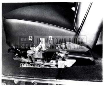
- Remove the front seat side panel kick pads. Loosen the two bolts (See Figure 137, A & B) holding the hood hinge bracket to the body and the one bolt (See Figure137, C) on the bracket of both hinges.
- Carefully remove the hood prop and lower the hood into the desired fit or position.
- Tighten bolts “A” and “B” to full tensions.
- Carefully raise and prop the hood and tighten bolt “C”.
- Replace hood springs as directed in BPS article “Removing and Replacing Hood Spring” at points 2 and 3 as previously described.
1953 HOOD SPRING REMOVING & REPLACING
ALL SERIES
The hood spring remover and replacer tool, as described in this BPS, article titled “1953 Hood Spring Remover and Replacer” is what its name implies. Therefore to use this tool, an external force must be’ used to flex the hood spring so that the tool may slide in between the coils of the hood spring.
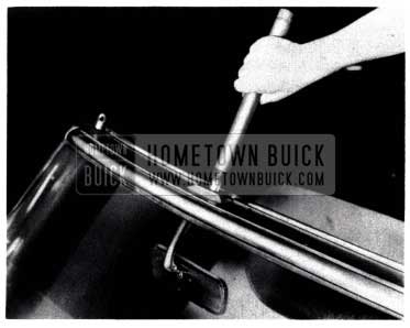
To remove a hood spring, raise the hood to the position that extends the spring to its greatest length. This hood position will place the hood hinge in what is referred to as its “center position”. With the spring extended to its furthest point, place the tool as shown in Figure 138 over the spring.

1953 Buick Hood Spring Removal
Be sure that the tool is forced into the spring as far as possible. When the spring is extended properly and the tool is in place there will be four turns of the spring exposed at each end of the tool. See Figure 138.
With the tool in place a leather strap must be wrapped around the spring and tool to be doubly sure that the spring stays in the tool. See Fig. 138.
To remove the spring from the hinge, raise the hood, thereby letting the hood hinge pass over center, and the spring tension will be transferred from the hinge to the tool. The spring and tool can then be removed from the hinge assembly. It must be remembered, that with a spring removed, the hood will not stay up. As a safety precaution, the spring should be removed from the tool.
The hood spring can best be unloaded or loaded in the tool by use of a common shop vise.
To equip a shop vise for spring stretching purposes as for loading or unloading the hood spring tool, follow these instructions:
- Drill two holes in the vise and tap 5/8” deep for 2 – 1/2″ x 13 cap screws.
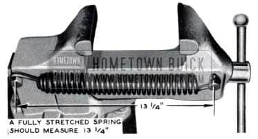
- One hole is drilled in the stationary jaw and one hole in the movable jaw (See Fig. 139) so that the jaws may be closed allowing a center distance between bolts of 9 1/2″ and they may be opened to a center distance between bolts of 13 1/4″.

1953 Buick Hood Spring Adjustment
To stretch a spring, close the vise and hook the hood spring over the bolts in the vise. Open the jaws, thereby stretching the spring until the bolt centers are 13 1/4″ apart (See Figure 140).
1953 Buick Hood Spring Tool
Detach or insert the hood spring tool into the spring. If the tool is to size and the spring stretched to its proper distance, there will be four turns of the spring outside of the tool on each end as shown in Figure 139.
With the tool now loaded, replace the hood spring on the hinge of hood. To release pressure on the spring, raise the hood in such a manner as to bring the hinge points, where the spring is to be attached, as close together as possible.
NEW HOOD LATCH
ALL SERIES 1953
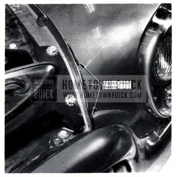
Due to improper hood alignment and hood spring adjustment, the leading inner edge of the front fenders are sometimes hit by the hood when it is lowered. To alleviate this fender paint damage as illustrated in Fig. 141, a new, longer hood latch dovetail bolt (Gr. 8.083 No. 1165055) as shown in Fig. 142 and a new lower hood latch (Gr. 8.080 No. 1165042) are being used in production.
1953 Buick Fender Paint Damage
1953 Buick Hood Latch
The new lower hood latch is interchangeable with all first production units and will fit both the first and after production hood dovetail bolts. The new, longer hood dovetail bolts will fit both first and after production lower hood latches. However, some rework is necessary in order to use the new type dovetail bolt on jobs with the first or early production lower hood latch.
If complaints are received on fender paint damage due to hood strikage, as described previously, it is suggested that the proper hood alignment procedure as outlined on Page 122 of this BPS be followed. If satisfactory hood alignment cannot be achieved, installation of the new longer hood dovetail bolt should be made.
Following is the suggested procedure for installing the new dovetail bolt on first production jobs.
- Remove lower hood latch.
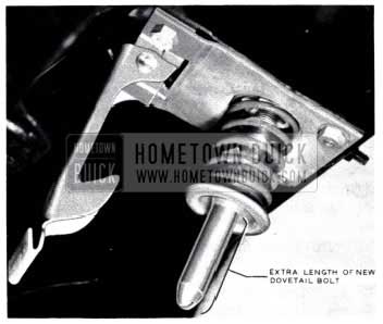
- Remove the bolt securing the hood fastener latch mounting panel brace to the .hood panel and turn it around so that the head of the bolt is facing the front of the car. (See Fig. 143)
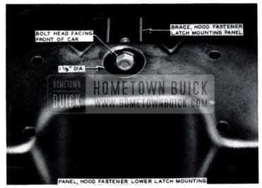
1953 Buick Hood Fastener Latch Bolt
Flat rate time for complete operation is .6 hr.
The Parts Department will handle and service both the first and after production dovetail bolts and lower hood latches.
EMERGENCY HOOD OPENING
ALL SERIES
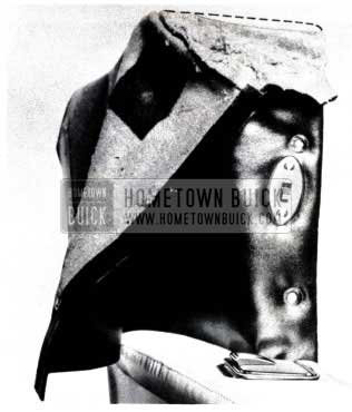
1953 Buick Emergency Hood Opening
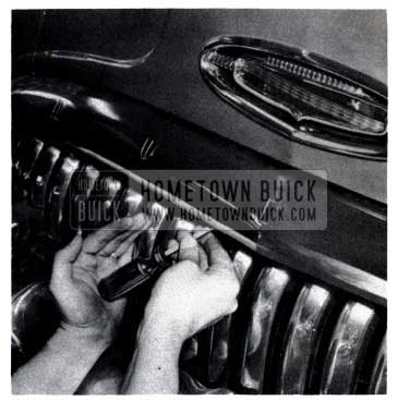
Fig. 144 illustrates a method of releasing the hood when failure or breakage of the control wire or any of the releasing mechanism is experienced. By sighting through the lower emblem slot, the screwdriver blade can be placed directly on the releasing lever (See Fig. 145).
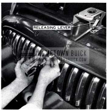
1953 Buick Hood Releasing Lever
By bumping the screwdriver with the palm of the hand, (Fig. 144) the lock will be released. Fig. 145 illustrates the position of the screwdriver when used as illustrated in Fig. 144.
It is cautioned, however, that care must be exercised not to mar the chrome grill area with the screwdriver when following this procedure.
If the hood is released and the hood remains closed and in the locked position, it may be that the locking bolt has become fouled under the lower hood latch. This condition, if present, can be observed by looking up between the splash pan and radiator and noting if the locking bolt is aligned properly in the center of the lower hood latch. A large screwdriver or pry bar may be used to align the locking pin if it is off center.
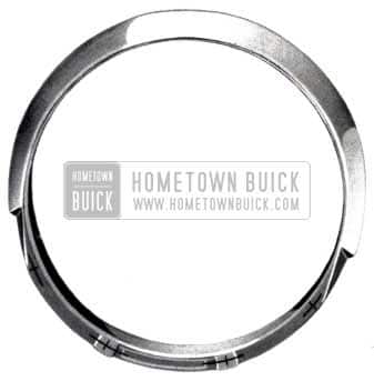
HOOD ORNAMENT RING REPLACE
1953 SERIES 40
There are some instances where the hood ornament ring, Group 1.265, No. 1345992 has been broken off.
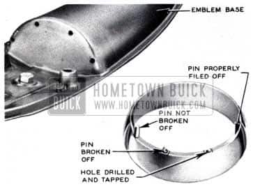
In production, the hood ornament ring is secured to the ornament base by four metal pins or rivets. If the old hood ornament ring is still available, it will be necessary to file off the remaining burrs left from the four broken rivets until they are flush with the bosses (See Fig. 146).
1953 Buick Hood Ornament Ring Replace
If it is necessary to use a new ring, the rivets must be filed flush with the bosses to allow for the drilling of holes.
Procedure:
- File off all rivets and/or burrs.
- Center punch the four locations as shown in Figure 147.
1953 Buick Hood Ornament Ring
1953 Buick Hood Ornament Assembly
Flat Rate – Hood ornament mounting ring – installation includes: R & R hood ornament – drilling and taping holes in mounting ring.
1953 Series 40 – 1.0
HOOD INSULATION CEMENT
It has been called to our attention that several dealers are ordering cement No. EC-1128 from the Minnesota Mining and Manufacturing Company for the purpose of re-cementing hood insulation to the underside of hoods. This particular cement is made on special order in large quantities for certain manufacturers and is not available in small quantities.
It is our recommendation that 3M Weatherstrip cement (black) be used for cementing the insulation to the hood.
Would you please act accordingly.
INSTRUCTIONS FOR INSTALLING NEW PARTS & REWORKING SEAT ADJUSTERS ON “MANUALLY” OPERATED 1953 FRONT SEATS
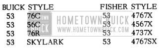
Some of the first type 1953 56C ‘s, 56R ‘s, 76C ‘s, 76R ‘s and Skylarks had the wrong parts in the seat adjusting mechanism. These cars will have to be campaigned, using a special kit which has been made up and is available through the Parts Department according to the trim combination in the car. The kit for all 70 Series and 56C ‘s which have to be reworked consist of two actuating plate assemblies and is available under Group 11 .588, Part 1391574. It is not necessary to worry about trim combinations on any of the hydraulically operated seats.
The 56R ‘s require a new seat side panel and for this reason the exact kit for the trim combination originally used in the car will have to be used. Following is a table of the kit part numbers for the combinations on these cars.
Factory records provided the data as to what zone and to which dealer each of the jobs that are to be changed was sent to. The zones have been sent the records of the cars to be campaigned in their area and they in turn will forward to each dealer a record of just which cars he, the dealer, is to campaign. The information sent to the dealer will be the order, serial and engine numbers plus the trim combinations, style and color combination.
Accordingly, the following procedures have been developed to illustrate and explain the rework operations. A copy of this rework will be furnished with each rework kit.
PARTS REQUIRED
- Left Seat Side Panel Assembly
- Seat Adjuster Handle Remote Control Assembly.
- Seat Adjuster Handle.
- Seat Adjuster Handle Screw.
- Seat Adjuster Actuating Plate Assembly-Right.
- Seat Adjuster Actuating Plate Assembly-Left.
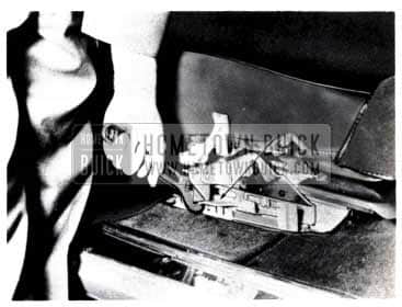
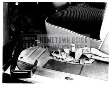
REWORK PROCEDURE
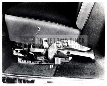
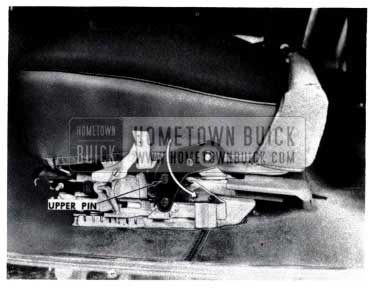
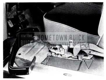
- Remove seat adjuster knob “A” (See Fig. 149). Also both seat side panel assemblies.
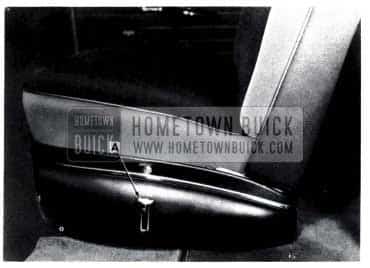
1953 Buick Seat Adjusters
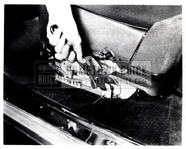
1953 Buick Remove Seat Adjuster Handle Remote Control Assembly
1953 Buick Remove Seat Back Center Hinge Pin Cover Plate
1953 Buick Install Seat Adjuster Handle Remote Control Assembly
1953 Buick Remove Seat Back Panel Assemblies
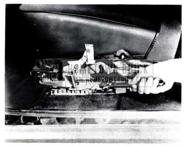
1953 Buick Remove Seat Adjuster Bolts
1953 Buick Remove Seat Adjuster Actuatating Plate
NOTE: Do not drive hinge pins inboard.
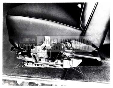
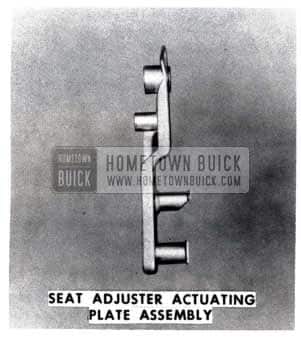
- Paint new seat adjuster actuating plate assemblies to match seat back outer arm color and install. Then install the following parts:
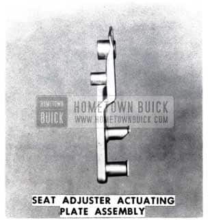
1953 Buick Seat Adjuster Actuating Plate Assembly
- Rubber washers on actuating plate assemblies.
- Fiber washers on both seat back inner hinge pins.
- Both seat backs on outer hinge pins and inner brackets.
- Cup washers and cotter pins on outer hinge pins.
- Cotter pins on inner hinge pins.
- Cover plate for seat back inner hinge pins.
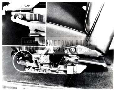
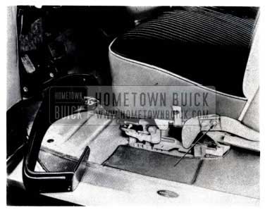
NOTE: In the following three (3) steps it is not necessary to remove the seat back and actuating plate assemblies. However, they have been removed in the photographs for illustrative purposes.
- Bend indicated flange 15 degrees outward from vertical on left and right seat adjusters. This operation will not be necessary on those flanges which were bent in production.
1953 Buick Inspect Seat Flange
1953 Buick Inspect and Bend Seat Flange
1953 Buick Inspect Seat Flange for Clearance
1953 Buick Lubricate Moving Seat Parts
NOTE: Locking slots are shown in preceding illustration.
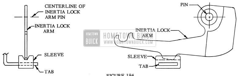
1953 Buick Check Operation of Inertia Lock
- Make sure seat backs are in full rear position, contacting the rubber bumpers.
- Make sure seat back rubber bumpers are not misaligned and holding seat backs slightly forward.
- If alignment of the seat back rubber bumpers does not provide the necessary clearance, remove the rubber bumpers and recheck inertia lock. If the 1/16 inch spacing is obtained by removal of the bumpers, trim sufficient stock from bumpers to maintain this clearance and install bumpers to seat assembly.
- If the 1/16 inch gap cannot be obtained by the preceding operations, file or grind the lock arm and/or the lock pin. Do not remove more than 1/32 inch of stock from either the arm or pin.
NOTE: After any seat back adjustments are made, the left and right side panels should be removed and the inertia locks checked to determine if proper clearance has been maintained at the inertia locks and pins. - If after the preceding checks are made the inertia lock is still inoperative, replace the complete seat adjuster assembly on the affected side. The procedure for removal and installation of the seat adjusters is illustrated and explained following the rework operations.
REMOVAL OF SEAT ADJUSTERS
1953 Buick Remove Seat Adjuster Handle Remote Control Assembly
- Remove seat adjuster handle and both seat side panel assemblies.
1953 Buick Remove Seat Adjuster Bolts
1953 Buick Removal of Seat Adjusters
NOTE: If only one seat adjuster assembly is to be replaced, it is necessary to remove only the seat back and actuati’1g plate on the side affected.
INSTALLATION OF SEAT ADJUSTERS
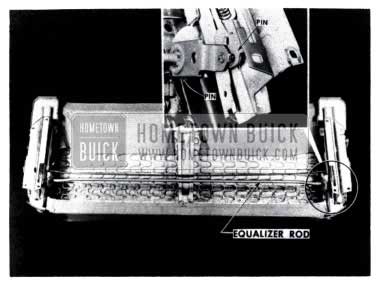
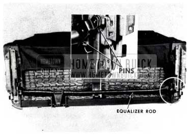
- Assemble the seat adjusters, equalizer rod and locking rod to the seat bottom frame, making certain the following parts are properly located:
1953 Buick Seat Adjuster Assembly
1953 Buick Installation of Hydraulic Seat Adjusters
1953 Buick Seat Adjuster Attaching Bolts Alignment
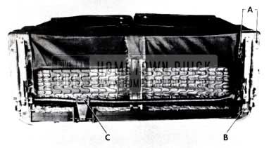
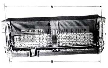
NOTE: Re-measure “A” after each adjustment since “A” will change slightly when “B” is changed. Also, check to see that the rear end of left adjuster is still inboard on its sliding action.
- With the aid of a helper, lock seat adjusters in the third locking slot from the front and turn cushion over to an upright position.
- Install the actuating plates and seat backs.
- With aid of a helper, set seat assembly in car and attach to floor pan as follows:
- With the rear end of the left adjuster as far inboard as possible, align the attaching bolt holes on both right and left sides and install the two (2) outer bolts on the right adjuster.
- Next, hold the rear end of the left adjuster inboard and install the two (2) outer bolts on the left adjuster.
- Check beneath seat to make sure both ends of equalizer rod are properly engaged.
- Then install the four (4) remaining attaching bolts.
- Check the operation of the seat assembly and inertia lock and install seat side panels and adjuster handle.
INSTRUCTIONS FOR INSTALLING NFW PARTS & REWORKING SEAT ADJUSTERS ON “HYDRAULICALLY” OPERATED 1953 FRONT SEATS
1953 Buick Roadmaster Series Fisher Style Numbers
PARTS REQUIRED
- Seat Adjuster Actuating Plate Assembly – Right
- Seat Adjuster Actuating Plate Assembly – Left
REWORK PROCEDURE
- Remove both right and left seat side panel assemblies. On the left side it is not necessary to disconnect the seat adjuster Hydro-Lectric switch.
1953 Buick Remove Seat Side Panel Assemblies
1953 Buick Remove Seat Back Panel Assemblies
- Remove seat back center hinge pin cover plate. Remove cotter pins from right and left seat back inner hinge pins: NOTE: Seat removed from car for illustrative purposes.
- Remove cotter pin and cup washer from both seat back outer hinge pins.
1953 Buick Remove Seat Cotter Pin
1953 Buick Seat Adjuster Actuatating Plate Assembly
Remove the rubber washers, and then slide the seat adjuster actuating plate assemblies from the outer hinge pins. NOTE: Do not drive hinge pins inboard.
1953 Buick Remove Seat Adjuster Actuatating Plate
- Rubber washers on actuating plate assemblies.
- Fiber washer on both seat back inner hinge pins.
- Both seat backs on outer hinge pins and inner brackets.
- Cup washers and cotter pins on outer hinge pins.
- Cotter pins on inner hinge pins.
- Cover plate for seat back inner hinge pins.
NOTE: In the following three (3) steps it is not necessary to remove the seat backs and actuating plate assemblies. However, they have been removed in the photographs for illustrative purposes.
- Inspect indicated flange. If it is vertical, bend 15 degrees outward from vertical on both right and left seat adjusters. If it is already bent at this angle, no operation is necessary.
1953 Buick Inspect Seat Flange
1953 Buick Inspect and Bend Seat Flange
1953 Buick Inspect Seat Flange for Clearance
1953 Buick Check Seat Operation
- Check the engagement of the two (2) pins at each end of the equalizer rod. This should be checked with the seat in the forward and rearward positions.
1953 Buick Check Operation of Inertia Lock
- Make sure seat backs are in full rear position, contacting the rubber bumpers.
- Make sure seat back rubber bumpers are not misaligned and holding seat backs slightly forward.
- If alignment of the seat back rubber bumpers does not provide the necessary clearance, remove the rubber bumpers and recheck inertia lock. If the 1/16 inch spacing is obtained by removal of the bumpers, trim sufficient stock from the bumpers to maintain this clearance and install bumpers to seat assembly.
- If the 1 /16 inch gap cannot be obtained by the preceding operations, file or grind the lock arm and/or the lock pin. Do not remove more than 1/32 inch of stock from either the arm or pin.
NOTE: After any seat back adjustments are made, the left and right side panels should be removed and the inertia locks checked to determine if proper clearance has been maintained at the inertia locks and pins. - If after the preceding checks are made, the inertia lock is still inoperative, replace the complete seat adjuster assembly on the affected side. The procedure for removal and installation of the seat adjusters is illustrated and explained following the rework operations.
- If the inertia locks are found to operate satisfactorily, install the seat side panel assemblies.
REMOVAL OF SEAT ADJUSTERS
1953 Buick Remove Seat Adjuster to Floor Pan
- Disconnect positive battery cable.
- Remove both seat panel assemblies.
- Remove seat regulator cover from front of seat assembly.
- Remove nut which attaches seat regulator to seat assembly and disengage stud from bracket.
- Manually move seat to full rear position and remove two (2) seat adjuster to floor pan attaching bolts from the front of each seat adjuster.
- Manually move seat to full forward position and remove two (2) seat adjuster to floor pan attaching bolts from the rear of each seat adjuster.
- With the aid of a helper, remove the seat assembly from the car and place upon a bench in an upright position.
- Remove right and left seat backs and actuating plates and place seat cushion on a covered bench with the bottom of the cushion exposed.
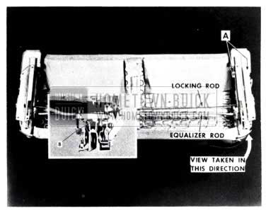
- Remove the two (2) rear seat adjuster to seat bottom frame attaching bolts “A” from each seat adjuster.
1953 Buick Move Seat Adjusters to Rear Position
NOTE: If only one seat adjuster assembly is to be replaced, it is necessary to remove only the seat back and actuating plate on the side affeved.
INSTALLATION OF SEAT ADJUSTERS
1953 Buick Seat Adjuster Installation
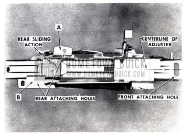
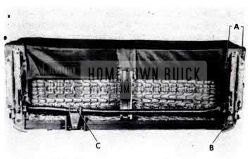
- Assemble the seat adjusters and equalizer rod to the seat bottom frame, making certain the following parts are properly located:
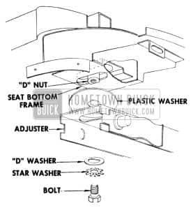
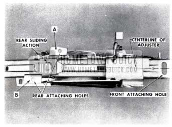
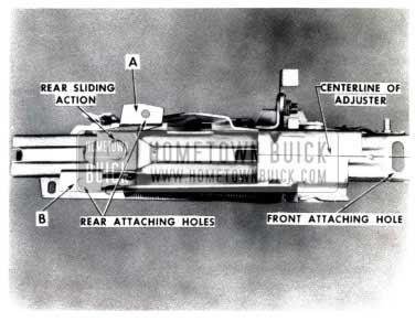
- Rear attaching bracket is positioned with higher surface “A” at front (outboard) and lower surface “B” to the rear (inboard).
- Plastic washer is placed between adjusters and seat bottom frame at the front attaching bolt.
- Front attaching bolt is centered with relation to the centerline of the adjuster and the floating “D” nut is centered in its cage on the seat bottom frame. Note that the flat washer is also of a “D” design and must engage the head of the floating nut.
1953 Buick Seat Adjuster Assembly
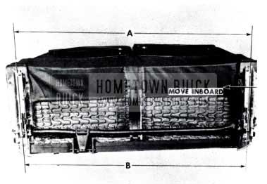
1953 Buick Move Seat Adjusters
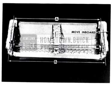
NOTE: Remeasure “A” after each adjustment since “A” will change slightly when “B” is changed. Also, check to see that the rear end of left adjuster is still inboard on its sliding action.
- With the rear end of the left adjuster as far inboard as possible, align the attaching bolt holes on both right and left sides and install the two (2) outer bolts on the right adjuster.
- Next, hold the rear end of the left adjuster inboard and install the two (2) outer bolts on the left adjuster.
- Check beneath seat to make sure both ends of equalizer rod are properly engaged.
- Then install the four (4) remaining attaching bolts.
FRONT SEAT ADJUSTER
1953 BUICK, TWO DOOR STYLES
Because of the design features of the new “Easy Entrance” front seat adjusters, the removal and installation operations of the adjusters and front seat assembly are more complex than on previous models.
Particular attention should be paid to the dimensional checks which are to be made prior to installation. These checks, and the proper positioning of the left adjuster, must be made to insure parallelism of the adjusters.
Since the left adjuster is free to move in and out after the adjuster to floor pan bolts are loosened or removed, many normal installation and maintenance operations are affected.
The following illustrate and explain the removal and installation of the front seat adjuster.
REMOVAL
- Remove both seat side panel assemblies.
- On hydraulic styles:
- Disconnect positive battery cable.
- Remove seat regulator cover from front of seat assembly.
- Remove nut which attaches seat regulator to seat assembly and disengage stud from bracket.
- Move seat to full rear position and remove two (2) seat adjuster to floor pan attaching bolts from the front of each seat adjuster, indicated by arrows in Figure 183.
1953 Buick Remove Seat Adjuster to Floor Pan
1953 Buick Remove Seat Backs
- Remove pin “C”, disengage equalizer rod from adjusters and remove rod from seat assembly. (Figure 184)
- Remove seat adjuster assemblies from seat bottom frame.
- Disengage equalizer rod from adjusters and remove.
- Disconnect locking rod by rotating adjusters from ends of rod.
- Remove seat adjuster assemblies from seat bottom frame.
NOTE: If only one seat adjuster assembly is to be replaced, it is necessary to remove only the seat back and actuating plate on the side affected.
INSTALLATION
- Assemble the seat adjusters, locking rod (manual styles) and equalizer rod to the seat bottom frame making certain the following parts are properly located:
- Position the rear attaching bracket with the higher surface “A” at front (outboard) and lower surface “B” to the rear (inboard). Figure 185)
1953 Buick Seat Adjuster Attachments
1953 Buick Seat Adjuster Assembly
1953 Buick Check Operation of Seat Assembly
NOTE: Remeasure “A” after each adjustment since “A” will change slightly when “B” is changed. Also, check to see that the rear end of left adjuster is still inboard on its sliding action.
- With the rear end of the left adjuster as far inboard as possible, align the attaching bolt holes on both right and left sides and install the two (2) outer bolts on the right adjuster.
- Next, hold the rear end of the left adjuster inboard and install the two (2) outer bolts on the left adjuster.
- Check beneath seat to make sure both ends of equalizer rod are properly engaged.
- Then install the four (4) remaining attaching bolts.
REINFORCEMENT OF FRONT SEAT
1953 SERIES 40, 2-DOOR STYLES
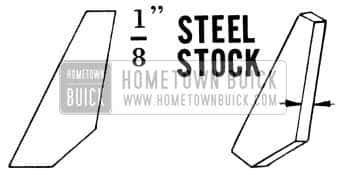
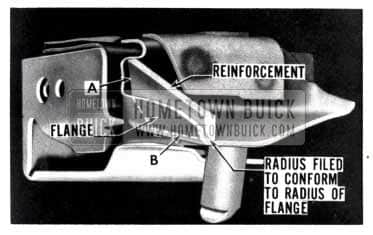
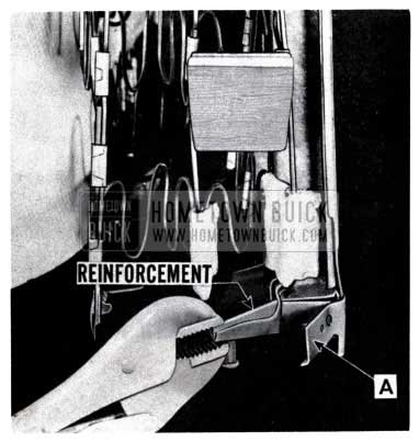
If the front seat backs, on the 1953 Series 40, 2 Door Styles, have taken a “set” to the rear of the normal position because of bent center hinge arm supports, the seats should be re-aligned and a reinforcement should be added to each front seat back frame center hinge arm support.
- From 1/8 inch steel stock, cut out two (2) reinforcements using the template shown in Fig.188.
1953 Buick Front Seat Reinforcement
1953 Buick Front Seat Back Trim Romoval
1953 Buick Front Seat Flange Reinforcement
1953 Buick Bend Front Seat Flange
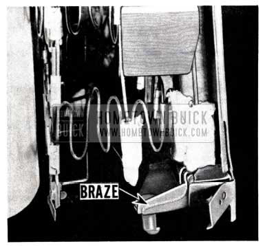
1953 Buick Remove Front Seat Clamp and Braze
Also, apply a bead of brazing along the inner contacting surfaces of the reinforcement.
FRONT SEAT SERVICING
1953 BUICK “SUPER” AND “ROADMASTER” TWO-DOOR STYLES
The following parts are involved in the Seat Adjuster campaign, and the field is being referred to these parts by the Fisher Service Representatives who are conducting schools on this subject at the present time.
The following two Kits are released and include all the necessary parts for reworking the Front Seat Adjusters in accordance with Fisher Service recommendations.
Group 11.561 -Part 1391615 – Kit-Front Seat Adjuster Rework 1953 56R
INCLUDES
1953 Buick Front Seat Adjuster Kit Parts – Super Series
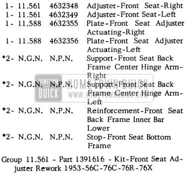
Group 11.561 -Part 1391616 -Kit-Front Seat Adjuster Rework 1953-56C -76C -76R- 76X
INCLUDES:
1953 Buick Front Seat Adjuster Kit Parts – Roadmaster Series and Convertibles
All parts in these Kits are released separately with the exception of those marked with an asterisk (*).
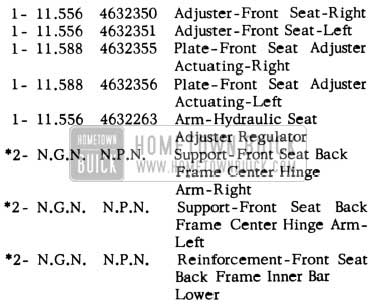
ln addition to these Kits, the following parts are also referred to:
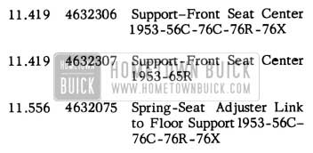
1953 Buick Front Seat Adjuster Part Numbers
INERTIA LOCK SLEEVE REPLACEMENT
1953 56R, 56C 76R, 76C, 76S
An engineering design change on the seat adjuster inertia lock sleeve has been incorporated to provide an improved seat adjuster inertia lock arm rest.
The following procedure may be used when replacing the early type sleeve with the current type sleeve:
- With the front seat assembly adjusted to the forward position, remove the seat side panel.
- Remove the early type inertia lock seat adjuster sleeve from the seat adjuster attaching tab. (See Fig.193)
1953 Buick Seat Inertia Lock Sleeve
1953 Buick Seat Inertia Lock Sleeve Replacement
FRONT SEAT HEATING
ALL SERIES
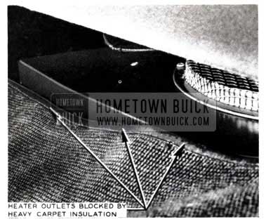
A few instances have been reported where the front carpet and jute insulator (used under the carpet), have blocked the heater outlets under the right front seat {See Figure 195).
1953 Buick Heater Outlets
As illustrated, all the warm air normally thrown into the right front seat area is blocked off and diverted under the carpet thus depriving this area of proper heating.

1953 Buick Replace Carpet
As shown in Figure 196, the jute insulation under the carpet must be between 2″ to 2W’ from the edge of the carpet. If the jute is found to be oversize, the excess should be cut off until the proper clearance is obtained.
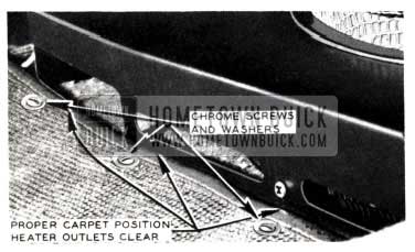
When replacing carpet use care to install and fit carpet edge against heater baffle base (See Figure 197).
1953 Buick Heater Outlets Clearance
As an added safeguard to keep the heater outlets open, install two or three chrome plated screws and washers at points indicated in Fig. 197. These will insure proper carpet position and prevent future heater blocking.
LEATHER SEATS & ACCESSORIES CLEANING
PROCEDURE FOR CLEANING VINYL AND PYROXYLIN COATED GENUINE AND IMITATION LEATHERS
The following procedure can be used when cleaning vinyl or pyroxylin coated genuine or imitation leathers:
- Using a mild soap, work up a thick suds on a piece of gauze or cheese-cloth and apply to surface.
Use as little water as is practical and brush moderately. - Remove soap suds with a clean damp cloth.
- Wipe surface dry with a soft cloth.
General Suggestions:
- Do not use solvents of any kind because permanent damage to the material may result.
- Remove soilage as quickly as possible after it has occurred.
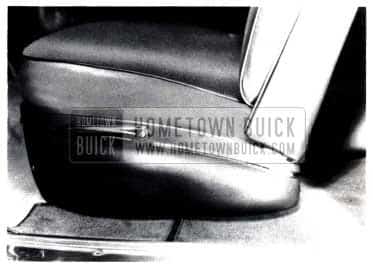
FRONT SEAT CUSHION
1953 BUICK “SKYLARK”
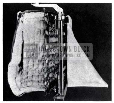
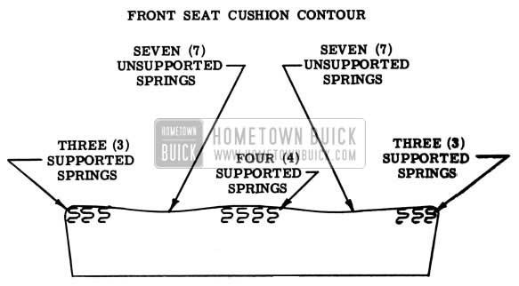
We wish to direct your attention to the design of the front seat cushion spring assembly used in the Skylark style body. This spring assembly was designed to provide a “saddle” type construction which lowers the driver and passenger and provides additional head room.
The center section and the right and left outer sections of the spring assembly are reinforced and retain the usual rigidity found in other cushions. The “saddle” areas of the spring assemblies are lower than the center and outer sections. The trim and padding will tend to lower in the “saddle” areas and follow the spring contour after some use.
This design characteristic should not be mistaken for a “sagging• condition. This is a standard production feature used in this body style.
Fig. 198 illustrates the supported and unsupported spring sections of the front seat cushion assembly.
1953 Buick Front Seat Cushion Contour
FRONT SEAT LEATHER SQUEAKS
1953 SERIES 50-70
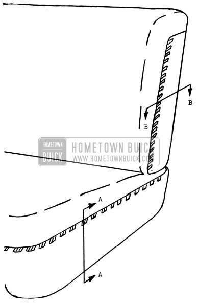
Our attention has been directed to a squeaking condition which develops at the points of contact between the front seat side panels and the imitation leather and/or genuine leather on the front seat cushions and front seat backs.
LUBRICATION OF SEAT SIDE PANELS AND BACK PANELS
- Hold cushion away from seat side panel and carefully apply a light coat of Grease Stick, or its equivalent, to the inner edge of the side panel as shown in Section AA. Do not apply lubricant any closer to the exposed “crown • of the side panel than is shown in Figure 199.
1953 Buick Lubrication of Seat Side Panels
NOTE: The application of this lubricant must be held to a minimum to prevent soiling the contacting trim or clothing.
- Repeat this operation for the seat back panel, as indicated in Figure 200.
1953 Buick Operation for Seat Back Panel
LEATHER FINISH CHANGE
GENUINE LEATHER FINISH CHANGE
Within a few weeks the finish on all genuine leather used by Fisher Body will be changed from pyroxylin to vinyl.
Since a chemical analysis is required to determine the difference tween pyroxylin and vinyl finishes used on leather and CLEAR LEATHER SEAL must not be used on vinyl finish, we are discontinuing the use of CLEAR LEATHER SEAL and no more will be sent to the field.
At present there is no known finish which can be applied to vinyl finish in the field.
DOOR VENTILATOR REGULATOR
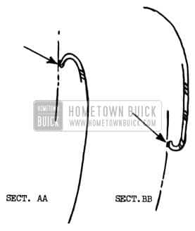
For 1953 production, the Door Ventilator Regulator Handle was re-positioned approximately 3/16” upward on the 56R-56C-76R-76C models. As a result of this change, it was necessary to remove 3/16″ stock from the Door Ventilator Die Cast attaching lugs to allow the regulator to be raised. Also, the Door Ventilator Glass Channel Tee Shaft was shortened the same amount to accommodate the raised regulator.
To accomplish this removal of 3/16” of stock from the Ventilator attaching lugs, the molds for casting the Ventilator Frames were revised and are no longer available to produce Ventilators and Frames with the attaching lugs having the original length. This affects service parts for the 1950, 1951, and 1952 subject styles.
For service purposes, in order to. compensate for this stock removal, the Parts Department will service the Ventilator Assemblies, Group 10.650 and Ventilator Frames, Group 10.656 with two (2) spacers wired to each part ordered for service requirements on the 1950, 1951, and 1952, 56R-56C-76R-76C. When installing these ventilators and frames, it will be necessary to insert the spacers between the attaching lugs and the ventilator regulator as shown in Fig. 201.
1953 Buick Door Ventilator Regulator
This will position the regulator in its proper location in the door inner panel and the belt finishing panel. The ventilator glass channel, with tee shaft and the tee shaft itself, will be serviced in both lengths for the proper models.
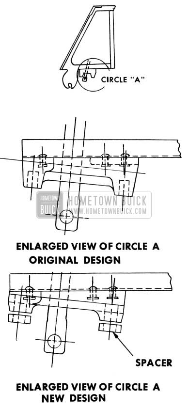
In conjunction with the above change, the 1953 Door Inner Panel, on the subject styles, was revised to accommodate the raised Ventilator Regulator. This consisted of raising the piercings for the Ventilator Regulator Handle Shaft and attaching bolts 3/16″.
Since the 1953 Door Inner Panel is also used in fabricating service doors for the 1950, 1951, and 1952 Series 56R, 56C, 76R and 76C models, these doors will also be affected. When installing a door on one of the above models, it will be necessary to file the inner panel 3/16” to allow sufficient clearance for the Ventilator Regulator. See Figure 202.
1953 Buick Door Inner Panel
In most cases, it will only be necessary to file the hole for the Ventilator Regulator Handle as there is usually sufficient clearance to allow for installation of the attaching bolts.
In both of the above cases, with the Ventilator Assemblies, Ventilator Frames and doors, all service parts in process will be used before they are fabricated as listed above. In all cases the original part number will be retained.
C V WINDOW SPRING CLIP
During September production, a spring clip was added to the front door ventilator regulators on all 1953 styles (See Fig 203)
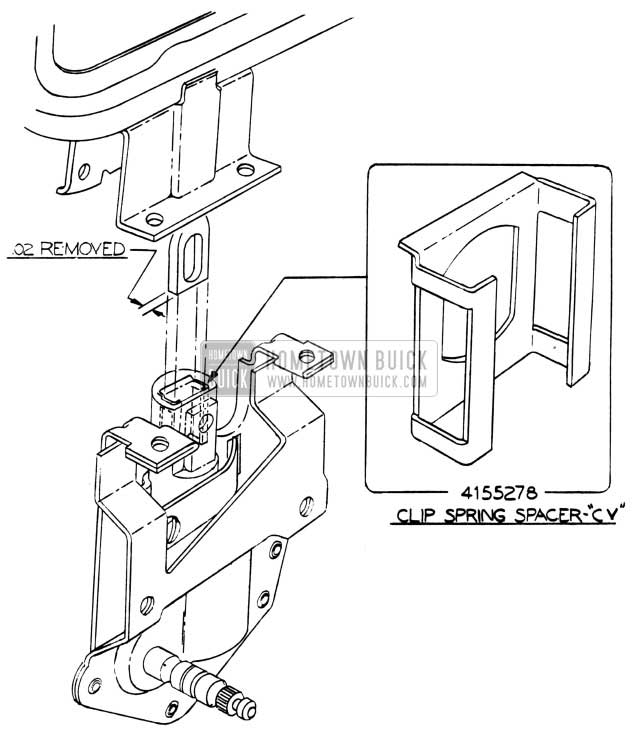
1953 Buick Door Ventilator Regulator Clip Spring Spacer
This clip helps prevent any tendency for the ventilator glass channel to flutter.
Due to this change, the Parts Department will replace the present regulators by new parts which includes the spring clip. However, all stock of regulators on hand will be used before any are supplied with the clip. Therefore, if the clip is needed and the regulator on hand does not contain one, the clip can be ordered separately under Group 10.661, Part 4155278 and inserted in the regulator.
If a regulator is received with a spring clip and is used on a first production car, the clip can either be removed or the ventilator tee shaft can be reworked by filing .020 stock from the side of the shaft. (See Fig. 203) Part numbers of the tee shaft will also be changed for service.
WINDOW SASH STOP
(See Page 165 of this Abridged Edition)
1953 BUICK 76X (SKYLARK)
It has been reported that in some instances the window sash upper channel stop has not engaged the draft strip properly. This condition has damaged the draft strip; allowed the upper sash channel to drop between the inner and outer door panels; and has bent the stop.
To correct, the following procedures may be used.
- Straighten stop if necessary.
- Adjust door glass assembly outboard to provide a brush contact with outer draft strip.
- Make corresponding outboard adjustments on door finish panel to provide brush contact of door glass to inner draft strips. This adjustment can be made by reshaping upper portion of door inner panel.
- Check action of stop by operating door glass through several cycles. Also, check by opening and closing door several times with the glass in the down position to determine if stop will disengage when shutting door. With glass in down position, stop should engage metal bead of draft strip, as shown in Fig. 204 and hold channel flush with reveal line of door.
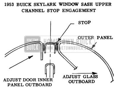
1953 Buick Skylark Window Sash
NOTE: The door glass adjustments for this style body are the same as those provided on past models.
Proper functioning of the window sash upper channel stop requires a brush contact of the channel with the draft strip on the door outer panel and the draft strip on the finishing panel.
LEAKING REAR QUARTER WINDOW HYDRAULIC LIFT CYLINDERS
1953 BUICK 50 & 70 SERIES TWO-DOOR HYDRAULIC STYLES
If a cylinder fluid leak is encountered in the rear quarter window hydraulic lift assembly, the lift frame should be checked for presence of the integral stop as shown in Fig.205.
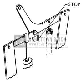
1953 Buick Rear Quarter Window Hydraulic Lift Cylinders
If the lift frame does not have the integral stop, the entire rear quarter window hydraulic lift assembly should be replaced. Replacement of only the cylinder will, in all probability, result in a second failure.
If the integral stop is present, replace the cylinder only.
RELOCATION OF REAR QUARTER WINDOW HYDRAULIC LIFT ASSEMBLY
ALL 1953 HYDRAULIC EQUIPPED TWO DOOR STYLES
EQUIPPED TWO DOOR STYLES
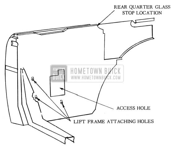
If the rear quarter window cannot be made to close completely by adjusting the rear quarter glass stop, the following procedure may be used to correct the condition:
Before removing the rear quarter window assembly from the car, try making the necessary adjustment by first loosening the window lift frame attaching bolts and lift and hold the window assembly up while tightening the lift frame bolts. If the window still does not close properly, proceed as directed:
- Remove rear quarter window and rear quarter window hydraulic lift assembly.
- Elongate upward the rear quarter window hydraulic lift frame attaching holes with a round file, as shown in Figure 206.
1953 Buick Rear Quarter Interior
FOLDING TOP COMPARTMENT SIDE PANEL AREA SEALING
1953 BUICK 46C, 56C, 76C, 76S (SKYLARK)
Four changes were recently incorporated in production in the Folding Top Compartment Side Panel area on the 46C Convertible body styles and three changes on the 56C, 76C, and 76S (Skylark) Convertible styles. These changes were made after the fabric water deflector was added above the bolt line in the rear quarter area. Since all changes were not made simultaneously, it will be necessary, in case of water entrance into the body, to check the right and left sides of the body to determine if the following four changes were made . Those changes which were not made in production would be made as service operations.
Change No.1
The drain slot at the forward end of the lower drain gutter has been enlarged to provide improved drainage.
Change No.2
A metal clip has been added at the forward end of the upper drain gutter to divert water from the top material binding into the gutter.
Change No.3
A metal water deflector has been added in each rear quarter to divert water into the drain gutter.
Change No. 4
(46 C only) Adam has been added at the rear end of the upper gutter to prevent water overflow.
To perform these service operations, certain parts must be procured. These parts are as follows:
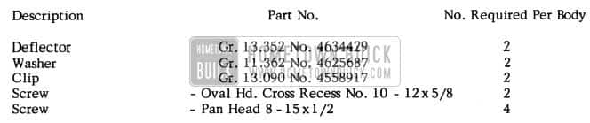
1953 Buick Folding Top Service Operation Parts
Following are the recommended procedures for making the above changes:
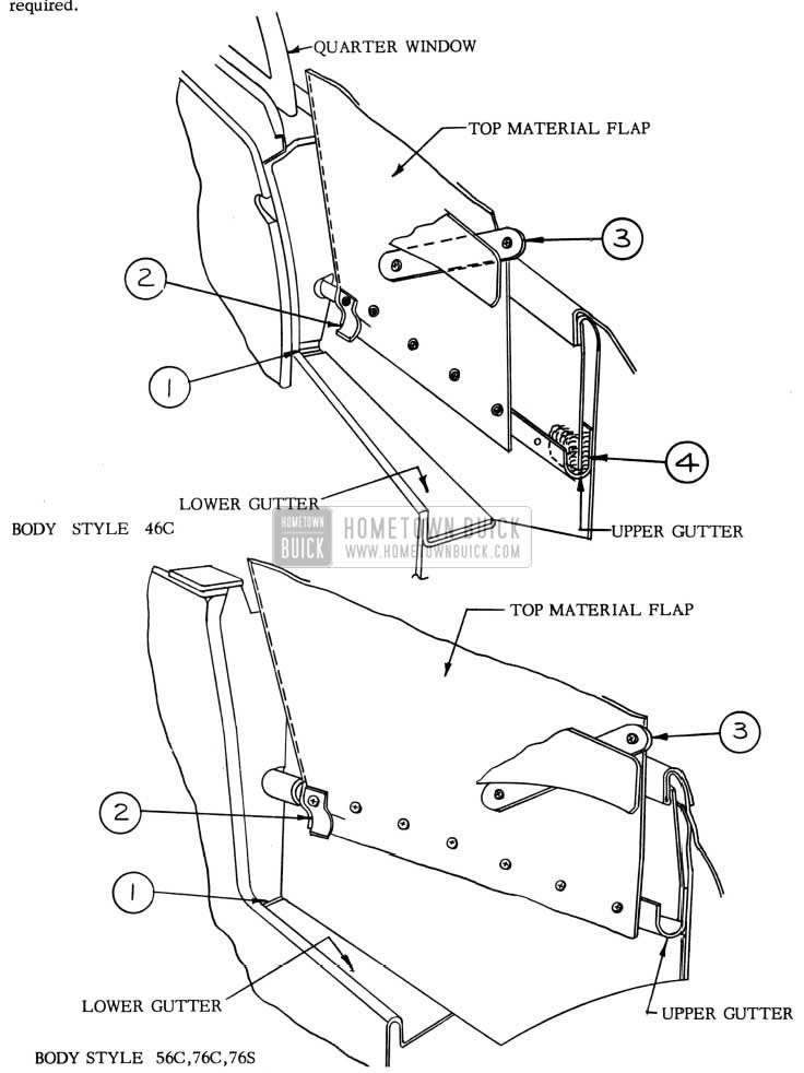
1953 Buick Folding Top Compartment Side Panel Area Sealing
Shown in Fig.207 is a sketch of the general area of the right rear quarter section of the convertible body. The four numbered arrows indicate the body locations covered in the following four service operations. The service operations shown for the right side of the body should also be performed on the left side where required.
CHANGE NO.1
DRAIN SLOT REWORK PROCEDURE
If the drain slot as shown in Fig208 below is not enlarged, it should be reworked as follows:
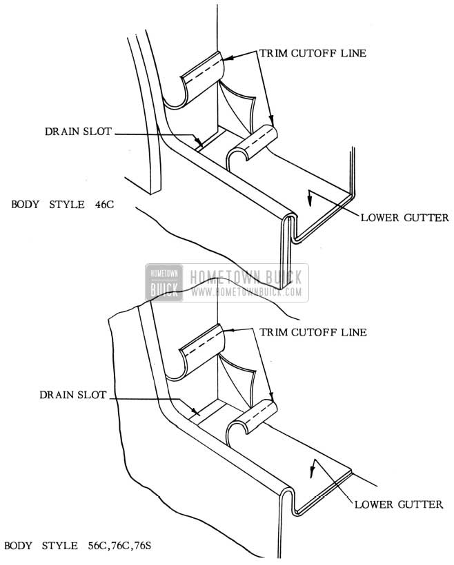
1953 Buick Folding Top Drain Slot Rework
- Remove rear seat cushion.
- Loosen the trim as shown in Fig. 208.
- Using a drift punch, or other suitable tool, enlarge the drain slot to provide increased drainage.
- Cut off and re-cement the loosened trim to conform to the enlarged drain slot as shown in Fig. 208.
- Install rear seat cushion.
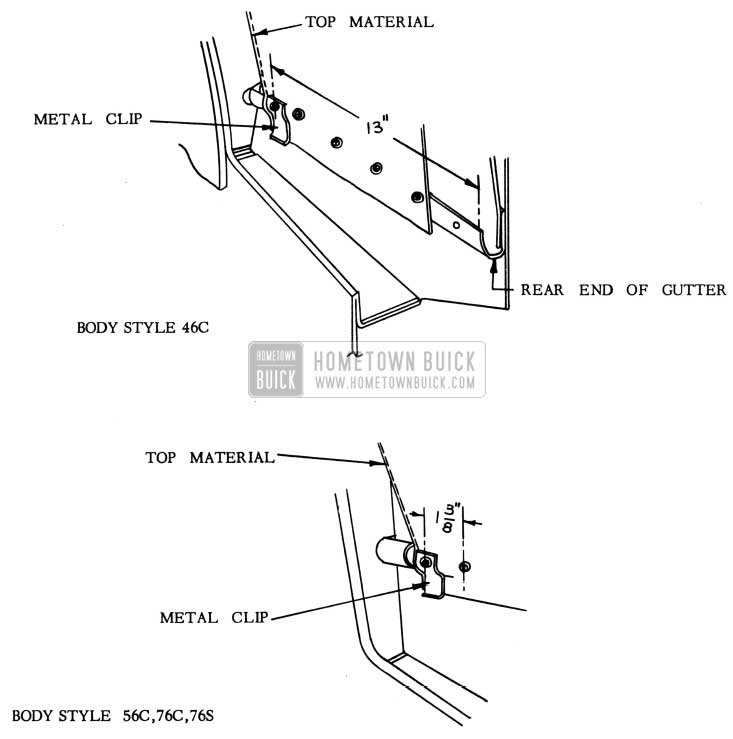
CHANGE NO.2
METAL CLIP INSTALLATION PROCEDURE
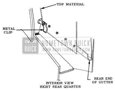
If a metal clip is not installed at the forward end of the upper gutter, as shown in Fig.209 below, a clip should be installed as follows:
1953 Buick Folding Top Metal Clip Installation
- Remove the rear seat cushion and back.
- Remove the rear quarter arm rest assembly.
- Mark location of clip screw as indicated in Fig. 209 and drill screw hole.
- Install clip with one self-tapping chrome screw and finish washer.
- Reinstall rear quarter arm rest assembly, rear seat back and cushion.
CHANGE NO.3
METAL WATER DEFLECTOR INSTALLATION PROCEDURE
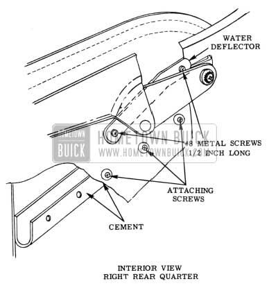
If the metal water deflector has not been installed as shown in Fig.210 below install water deflector in the position shown.
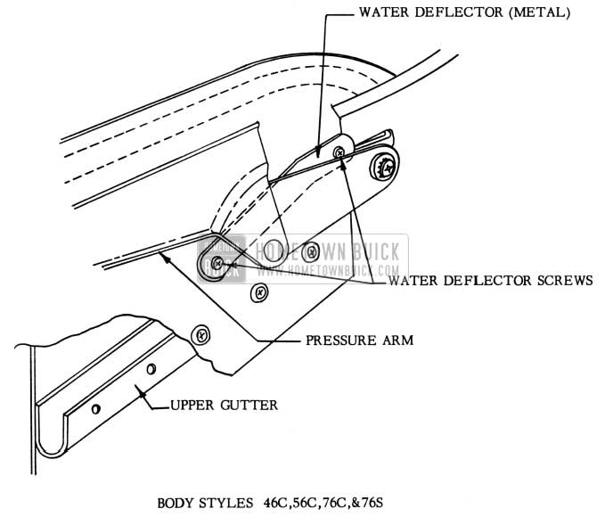
1953 Buick Folding Top Metal Water Deflector Installation
This will necessitate removal of two (2) screws and washers which were used prior to the incorporation of the water deflector. The procedure for installing the metal water deflector is as follows:
- Paint water deflector to match side roof rails.
- Remove rear seat cushion.
- Remove two (2) screws and washers from the water deflector attaching location.
- Install the metal water deflector with two (2) self-tapping metal screws as shown in Figure 210.
- Install rear seat cushion.
CHANGE NO.4
GUTTER DAM INSTALLATION PROCEDURE, 46C ONLY
If a dam is not installed at the rear end of the upper gutter as shown below in Fig.211, it should be installed as follows:
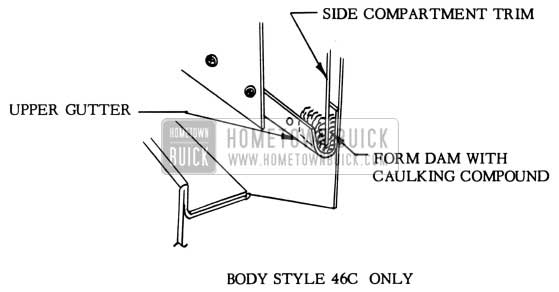
1953 Buick Folding Top Gutter Dam Installation
- Remove rear seat cushion.
- Detach rear end of top material flap from gutter.
- Loosen side compartment panel trim and install dam as shown in Fig. 211. NOTE: Side compartment trim should be imbedded in dam.
- Attach rear end of top material flap to gutter.
- Install rear seat cushion.
INSTALLATION OF FOLDING TOP TRIM ASSEMBLY
1950 MODEL BUICK “50” AND “70” SERIES
1951, 1952 AND EARLY 1953
MODEL BUICK “40”, “50”, AND “70” SERIES
In the latter part of April, 1953, a design change was made in the rear quarter area on 1953 model convertible styles. The sponge rubber filler sewed into the folding top trim assembly at the belt line was removed. In its place a fabric water deflector was added to the outside of the folding top trim. Also, several additional sealing operations were specified for the rear quarter area.
Current service replacement folding top trim assemblies for all of the above 1950, 1951, 1952, and 1953 models incorporate the design change in the rear quarter area. In the installation of service replacement folding top trim assemblies on the above models, it is essential that the following service operations be performed:
- Remove the original folding top trim in the usual manner.
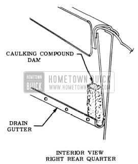
- Enlarge the drain slot in each rear quarter (Fig. 212) with a drift punch or other suitable tool.
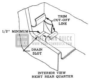
1953 Buick Interior View – Right Rear Quarter
Slot is directly below front end of metal drain gutter on rear quarter inner panel. Cut off trim, as indicated, to conform to enlarged slot.
1953 Buick Rear Quarter Interior View
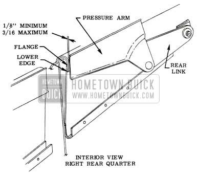
Caulk the flanges outboard, as necessary, to keep lower edges from contacting top material when top is installed. Lower edge of flanges should be a t least 1/8 inch outboard from upper section of flanges.
1953 Buick Right Rear Quarter Interior View
- Install the interior flaps between the pressure arms and outer panels.
- Position the trim on the folding top assembly framework to provide a continuous 3/16 inch spacing between the new fabric water deflectors and the moldings at the belt line. See Fig. 215.
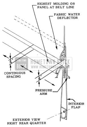
1953 Buick Right Rear Quarter Exterior View
NOTE: Do not attach interior flaps to metal gutters at this time.
1953 Buick Folding Top Rear Quarter Interior View
The deflectors should slope downward at the front to direct water into the gutters. Use care when drilling the screw holes to prevent damage to the quarter outer panels.
CAUTION: In making this installation, do not disturb the 3/16 inch spacing between the fabric water deflector and belt line.
1953 Buick Convertible Top Rear Quarter Interior View
FOLDING TOP ASSEMBLY INTERFERENCE
1953 BUICK-SKYLARK
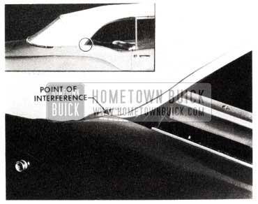
On some early production bodies of the 1953 Skylark, the corner of the rear quarter panel along the window reveal line interfered with the folding top material when the top assembly was in the raised position, causing wrinkled top material in this area.
The recommended rework procedure to correct the interference is as follows:
- Mark the rear quarter panel at the location shown on Fig. 218 after first determining the amount of metal to be removed to obtain proper clearance between the top material and the quarter panel at the window reveal line.
1953 Buick Folding Top Interference
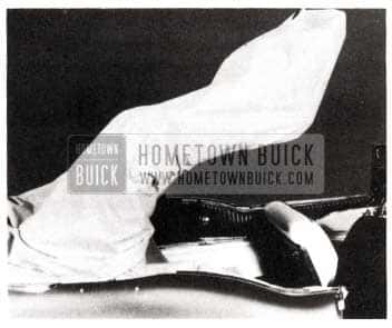
1953 Buick Folding Top Lowering
Also cover quarter trim and other adjacent trim assemblies.
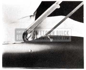
1953 Buick Folding Top Rear Quarter Work
NOTE: Cut only up to point “A“ as indicated on Figure 220. DO NOT CUT THROUGH REAR QUARTER PANEL FLANGE ALONG FORWARD EDGE OF AREA WHICH IS BEING REWORKED.
- Using a pair of metal snips, snip a long the flange up to point “B” as shown in Figure 221, view B.
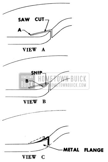
1953 Buick Folding Top Metal Flange
1953 Buick Installed Sheet Asbestos
1953 Buick Attach Rear Quarter Window Outer Draft Strip
NOTE: Asbestos repositioned for illustrative purposes.
- Paddle solder welded area and metal finish the reworked area.
- Spot finish the reworked area.
- Attach rear end of rear quarter window outer draft strip.
- Install rear quarter window finish panel.
NOTE: Figure 224 shows the reworked area and the way the top material should fit after the rework.
1953 Buick Folding Top Material Installed
CONVERTIBLE TOP TRIM DAMAGE AT REAR QUARTER AREA
1953 BUICK (40 SERIES) CONVERTIBLES
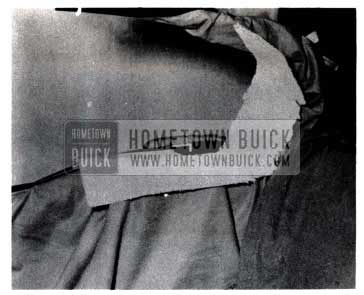
If the convertible folding top trim assemble, stay pad, or trim retainer have become damaged at the rear quarter area due to interference between the stay pad and trim retainer (pressure arm), the following rework should be performed to eliminate the possibility of additional or recurring damage to the top trim assembly, stay pad, or trim retainer.
NOTE: The amount of damage occuring on any one (1) body generally will depend upon the length of time the interference has existed. The first indications of this condition are bent trim retainers and torn quarter stay pads. If the repairs are made at this time, as outlined in the following procedure, no further damage will be experienced. However, if the trim retainer becomes severely bent, damage to the top trim assembly may result. This damage will necessitate replacement of the entire top trim assembly in addition to the rework procedure.
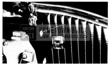
- Remove the damaged trim retainer. See Fig.227
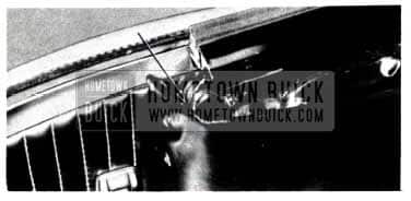
- Remove rear quarter rear belt molding. (F. 225)
1953 Buick Rear Quarter Top Material Flap
- Install protective cover along edge of belt molding.
- Remove rear quarter rear belt molding.
- Starting at the outer end of the “wire-on” binding, loosen the binding for a distance of twelve (12) inches.
- Detach rear quarter top material flap.
- Detach rear quarter top material along the belt line and rear bow area and fold forward.
- Detach the back curtain assembly to a point where the stay pad is accessible along the belt line and rear bow.
- Starting at the outboard edge, detach the folding top center stay pad from the rear bow far enough to gain access to the attaching point of the rear quarter stay pad only. It is important that the center stay pad not be detached completely from the rear bow.
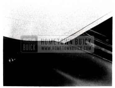
- Loosen the rear quarter stay pad outer section of webbing (See Fig.226) and relocate it inboard by overlapping the inner section of webbing until the stay pad assembly measures five (5) inches in width when assembled.
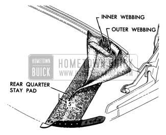
1953 Buick Rear Quarter Stay Pad Outer Section
1953 Buick Convertible Top Assembly
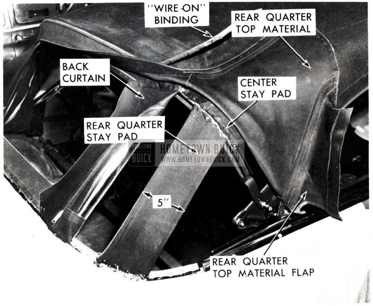
- Remove rear seat cushion and seat back. b. Detach folding top compartment bag sufficiently to gain access to wheelhouse.
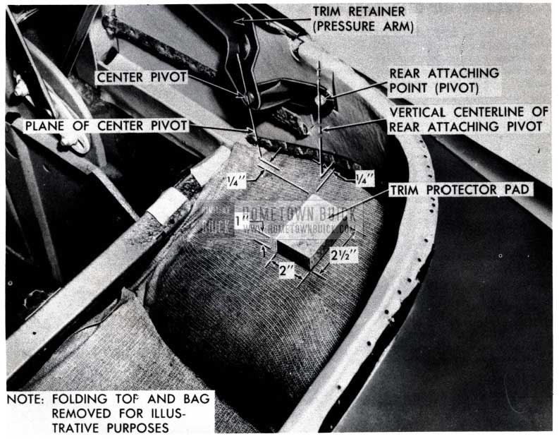
(NOTE: Folding top compartment bag removed for illustrative purposes only.) - Using successive layers of jute padding cemented together, make a trim protector pad which is 2 1/2″ x 2″ x 1″ in size.
- Cement the trim protector pad to the wheelhouse at location shown in Fig. 227.This pad will prevent the stay pad from hooking the “elbow” of the trim retainer (pressure arm).
FOLDING TOP INTERFERENCE
1953 BUICK “SKYLARK”
In certain instances there has been evidence of interference at the Quarter Trim Panel on some 1953 Buick “Skylark” styles when raising and lowering the Folding Top.
Following is a corrective procedure for eliminating this interference.
- Completely lower the folding top so that the extent of interference can be determined.
- Obtain sufficient clearance between side roof rail hinges and inside quarter trim panel, where indicated by arrow in Figure 228, by carefully reforming panel with a mallet and dolly.
1953 Buick Roof Rail Hinges Clearance
Raise the top half way and remove the upper trim panel screw to perform this operation.
CAUTION: Use extreme care when reforming so that trim is not scuffed or damaged. Use a smooth faced rubber or wood mallet.
- In some instances, after reforming the quarter trim panel, it will be necessary to use a suitable shim between the inside of the trim panel and the trim panel upper retaining bracket. Insert shim at the location indicated in Figure 229.
1953 Buick Trim Panel Upper Retaining Bracket
- Remove rear seat cushion and seat back. Remove quarter trim panel, turn back trim and cut off the required amount of metal stock, as shown at the dotted line in Figure 230.
1953 Buick Remove Rear Seat Cushion
- Use a hammer and dolly to reform reinforcing bead which was previously sheared off.
- Recement trim and reinstall quarter trim panel, seat back and seat cushion.
ROOF RAIL REWORK
1953 BUICK CONYERTIBLE
If a “bowed” condition is encountered in the Front Roof Rail which results in an excessive spacing between the Front Roof Rail and the Windshield Header at the Center Locking Stud the following conditions may occur:
- The excessive spacing may prevent the Front Roof Rail Weatherstrip from sealing properly at the Windshield Header.
- The excessive spacing may make it difficult to lock the Front Roof Rail to the Windshield Header.
If this condition is encountered it may be corrected by either of the following two alternate methods:
- Reshape the Front Roof Rail to eliminate the “bowed” condition by a “jacking” procedure as outlined.
- Replace the Front Roof Rail. A new Front Roof Rail should always be checked for contour fit on the Windshield header before painting and installing to determine if it fits correctly.
The following outlines the procedure to be followed when reshaping a Front Roof Rail by the “jacking” method.
If excessive spacing occurs between the front roof rail and the windshield header at the center locking stud as shown in Fig. 231, the front roof rail may be reworked as outlined in the following procedure.
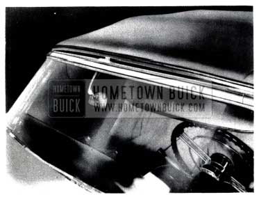
1953 Buick Convertible Roof Rail
NOTE: Use extreme caution in this rework operation as excessive “jack” pressure can damage the center and/or opposite locking studs or possibly cause windshield glass breakage.
REWORK PROCEDURE
- Remove the right locking stud from the windshield header and forcefully lock the top at the center and left locking studs.
- With the top securely locked as explained, turn floor mat back and place “jack” on wood block to distribute pressure on floor pan. (See Figure 232)
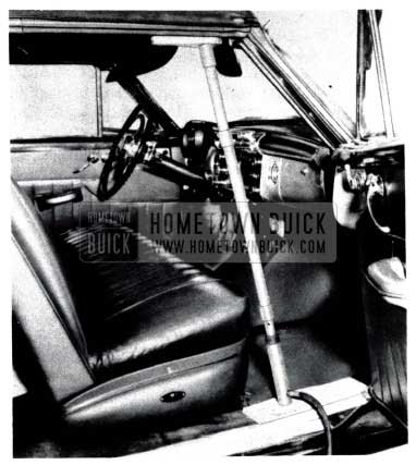
1953 Buick Convertible Roof Rail Rework
Upper end of” jack” should be placed against another wood block at the corner brace of front roof rail where side and front roof rails join.
1953 Buick Convertible Center Locking Stud
Only in extreme cases of contour misalignment should it be necessary to install a new front roof rail.
NOTE: This “jacking” procedure may be used on 1950 through 1953 Convertible styles.
CONVERTIBLE TOP CAMPAIGN
ALL 1953 56C, 76C, & 76X
All the 1953 56C, 76C, & 76X Buick convertibles built prior to Serial No. 17192384 (Flint) or jobs with Fisher Body identification tag number 56C-G 6508, 76C-G 3194, from BOP plants must be checked for loose Allen set screws at the locations shown in Fig. 234.
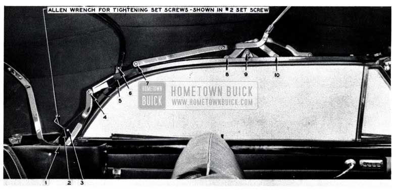
1953 Buick Convertible Top Rear Bow
A loose set screw at one of these locations will cause the convertible top linkage bolts to “back out” thus causing severe damage to the top. Any linkage bolts that are loose and/or partially backed out must be tightened first before the Allen set screws are securely tightened. It is necessary to use an Allen wrench as illustrated at number two (2) set screw location, Fig.234, in order to properly tighten the set screws.
All the above identified Buick convertibles should be campaigned and have these Allen screws tightened. AFA’s for .2 hr. maybe submitted. More than one car may be listed on one AFA provided all Serial numbers and body numbers are given.
We again wish to point out the importance of performing this campaign in order to prevent convertible top damage.
FOLDING TOP REAR BOW REWORK
1953 46C
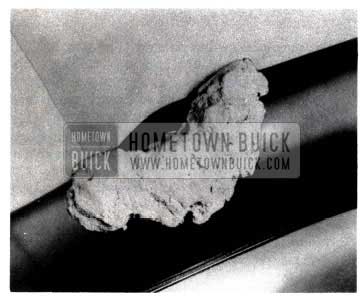
When a folding top cover is being replaced due to cuts or chafing in the rear quarter area the following rework should be performed to eliminate the possibility of recurring top material damage in this area.
- When the top material is removed, check the ends of the rear bow to see if it contains sharp edges and a gap as shown in Fig. 235.
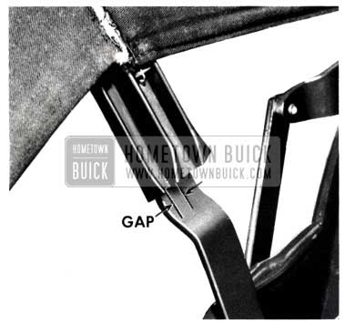
1953 Buick Convertible Top Rear Bow Gap
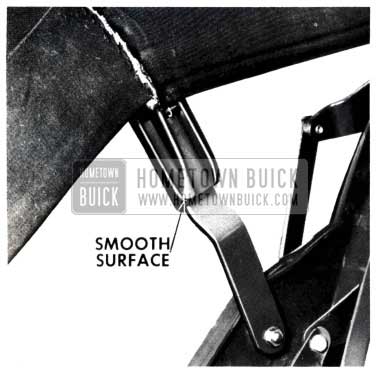
1953 Buick Convertible Top Rear Bow Surface
“ORLON” TOP CLEANING
BUICK SKYLARK
The procedure used for cleaning top materials on past model convertibles is also recommended for cleaning the new orlon top materials used on the above style convertibles. Refer to 1952 Buick Shop Manual – 13-4, Page 468, Paragraph e.
Generally, soilage can be removed with art gum .If dirt is heavily embedded in the fabric, the top should be thoroughly brushed with a whisk broom. In this brushing a minimum of pressure should be applied to those areas of the assembly which cover the metal bows of the top structure, since heavy abrasion will disturb the surface of the material appreciably, causing an unsightly appearance. After brushing, the top should be washed thoroughly with a neutral soap suds and lukewarm water. A cloth or brush with soft bristles should be used. Generous quantities of clean water should then be applied over the surface to remove any particles of soap which might remain. Volatile and other clear cleaners, naptha, gasoline or household cleansing and bleaching agents should never be used.
After cleaning, always be sure that the top is thoroughly dry before collapsing and folding it down.
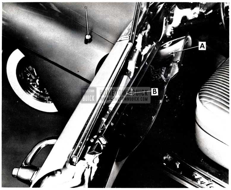
LUBRICATION OF TUBE & CONDUIT
1953 BUICK, SERIES 50 & 70
We wish to direct your attention to a lubrication operation which is required on the Hydro-Lectric system rubber conduit, located between the front body hinge pillar and door of the above styles.
To prevent the development of friction noises from rubber contacting metal at this point, apply a film of OC-4 compound, OC-7 Emulsion or equivalent silicone base lubricants. (Excess lubricant to be wiped off.) This lubrication must be repeated at five (5) to six (6) week intervals in order to keep the lubricant effective.
WINDOW SASH UPPER CHANNEL REWORK
1953 BUICK 76 X (SKYLARK)
Page 148 of this BPS outlined a service procedure for maintaining the window sash upper channel flush with the door reveal line on the first type channel.
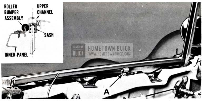
A more satisfactory method for maintaining the position of this channel has now been developed. This procedure applies only to first type installations which incorporate the external tab stop. It will not work on the second type where the outer draft strip has been removed. This procedure specifies the installation of a door window roller bumper assembly (Gr. 10.726 No. 4091152) on the upper surface of the door inner panel.
Following is the recommended procedure for installing the roller bumper assembly.
The 1953 Buick 76 X (Skylark) is equipped with one of two (2) types of window sash upper channels. These two (2) differ in length and method of retention at the window reveal line. The first type was the shorter and incorporated an external tab stop.
If the first type window sash upper channel has a tendency to drop down into the window opening, a door window roller bumper assembly may be installed to retain the upper channel in the proper position. The following procedure describes the method of installing this roller assembly. Second type channels may be retained by making stop adjustments.
INSTALLATION PROCEDURE
- Remove the door inside handles and detach the front section of the door belt finishing molding “A” as shown in Figure 237.
1953 Buick Skylark Window Sash Upper Channel
1953 Buick Skylark Window Sash Upper Channel Installation
NOTE: Roller should make light contact with the sash but should not touch glass.
- Check operation of upper channel. If necessary, install washers beneath roller to maintain a flush alignment of the forward end of the upper channel with the window reveal line. (See Fig.239)
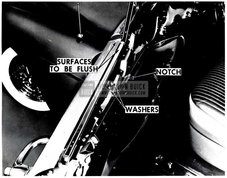
1953 Buick Skylark Window Sash Upper Assembly
1953 DOOR LOCK REWORK
If the door, with the locking rod knob in the locked position, can be opened to the “safety” position by actuating the outside push button, it is due to the interference of the door lock intermittent lever with the hook lever. The following procedure can be used to eliminate this interference thereby insuring proper operation of the door lock.
NOTE: Figs. 240 &. 241show the door lock removed for illustrative purposes only.
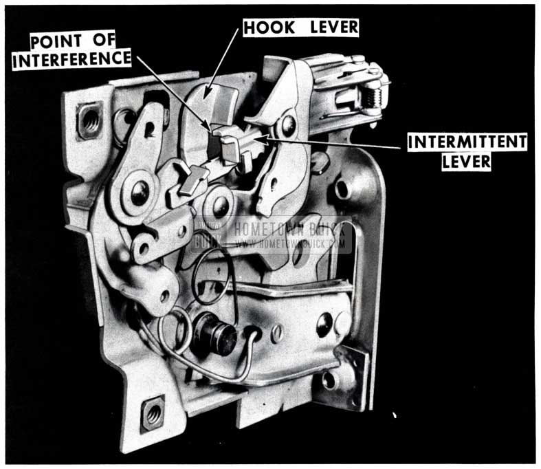
1953 Buick Door Lock
1953 Buick Door Lock Rework
- Lower the door glass.
- Remove locking rod knob and garnish molding or finish panel.
- Check the accessibility of the door lock intermittent lever through the opening between the door inner and outer panels. If access to the intermittent lever is available in this location, proceed with Step 5.
- If access to the intermittent lever is not available in this location, pull back trim pad far enough to gain working clearance to the door lock at the door inner panel access hole.
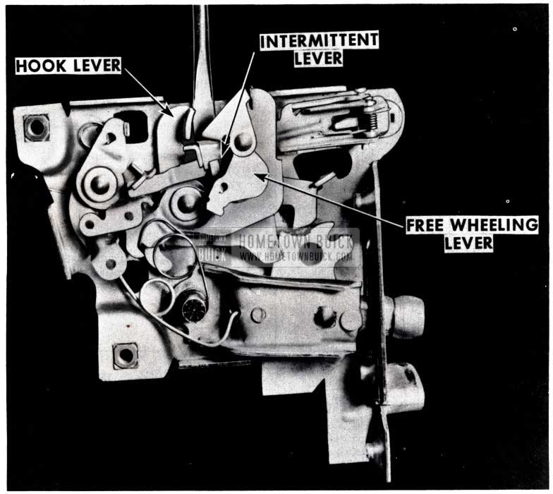
- Using a flat screw driver or other suitable tool, as shown in F. 241, CAREFULLY bend the door lock intermittent lever inboard far enough to gain operating clearance for the intermittent lever. A few thousandths of an inch bend is all that is usually required.
NOTE: In some cases, the rear door lock free-wheeling lever may be set in such a position that it will hinder the bending operation. If the free-wheeling lever must be tripped to its opposite position, care must be taken to return the lever to its original position.
- Check the operation of the door lock.
- Attach trim pad.
- Install garnish molding or finish panel and locking rod knob.
IMPROPER LIGHTER INSTALLATION
Reports show that the 12 volt cigarette lighters for the 1953 Series 50 and 70 Buicks are being interchanged or placed in the 1953 6 volt Series 40 jobs.
These 6 and 12 volt lighters are not the same and differ both from an electrical and design standpoint. It is not possible to install a 6 volt lighter in a 12 volt unit due to size difference, but it is possible to put the smaller 12 volt lighter knob or element into the larger 6 volt (Series 40) case or base.
If the 12 volt lighter element is used in a 6 volt unit it is possible that it will short out the lighter unit due to its smaller size. This short will trip the lighter circuit breaker or blow the lighter fuse depending on the type of lighter used, Rochester or Cosco. Should this condition occur, first replace the improper lighter element with the proper 6 volt lighter.
It is not necessary to discard or replace the blown lighter unit or case. Merely reset the circuit breaker or replace the fuse of the unit as directed in Section f., Page 10-76 of the 1952 Buick Shop Manual.
SERIES 50-70
The 1953 Rear Compartment Lid for the Series 50-70 will be serviced by the Parts Department, less the mounting holes for the Rear Compartment Lid Emblem.
The brackets which hold the emblem mounting screws in place will be wired to the Trunk Lid Inner Panel. Therefore, when installing a new Lid Group 12.181, Part No. 4197379 on a 1953 Series 50-70, it will be necessary to drill the four (4) holes for the emblem mounting screws. The drawing, Fig. 242, shows the size and location of these holes.
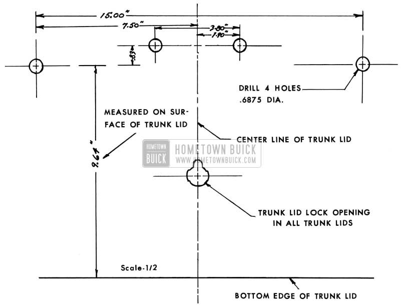
1953 Buick Trunk Lids Drilling Information
When the emblem is installed to the lid, it will be necessary to hold the brackets in place against the inner side of the outer panel and install the screws thru the brackets to hold the emblem.
BACK-UP & LICENSE LIGHT WIRE RELOCATION
1953 SERIES 40-50-70
For those so desiring, the wires leading from the back-up lamps and the license lamp may be concealed by relocating as follows:
- Layout and drill six (6) holes of .50 diameter from the bottom as shown in Fig. 243.
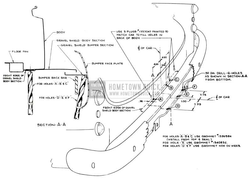
1953 Buick Back-Up and Licence Plate Relocation
Three (3) holes A, B, & C in the front edge of the gravel shield-body section and three (3) holes D, E, & F in the gravel shield-bumper section.
MOULDING, SIDE ROOF PANEL
1951, 56R -76R -75R
The Side Roof Panel Moulding-Rear (over the rear quarter window) Group 14.651 No. 4581985 Right used on the 1951 -56 R -76 R -75 R 1st jobs will no longer be available when present stock is exhausted. In order to supply replacements for this part, the Parts Department will replace the 1st type moulding by the present moulding Group 14.651 No. 4606967.
When this change was made in production during March of 1950, the Side Roof Panel Moulding-Front (above door window) was eliminated and the rear moulding was shortened approximately 2 inches, so that, it extended only to the front edge of the rear quarter window. Thus, when the new rear moulding is installed on a 1st- job car, there will be a gap of approximately 2 inches between the front and rear moulding. Therefore, when using the new rear moulding on a 1st- job car, it will be necessary to remove and discard the front section of moulding.
WIRE WHEEL SERVICING
In case there arises a need for wire wheel alignment, repair, or other similar service problems, the following list of Kelsey-Hayes Wheel Company distributors have equipment and are prepared to service these wheels. Due to the technical nature of setting up wire wheels and the special equipment required, it is recommended that service on wire wheels be performed by one of the following authorized distributors. They are listed alphabetically according to states.
Wheel, Rim & Parts Company
2021 Fifth Avenue, South
Birmingham, Alabama
Motor Rim & Wheel Service
2860 East Pico Boulevard
Los Angeles 23, California
Motor Rim & Wheel Service
3075 – 17th Street at Folsom
San Francisco 1, California
Quinn & McGill Motor Supply
437 Broadway
Denver 1, Colorado
Southeast Wheel & Rim
927 W. Forsyth
Jacksonville 3, Florida
Stone Wheel Incorporated
2540 South Wabash
Chicago 16, Illinois
Illinois Wheel & Brake Company
1111 East Washington
Springfield, Illinois
Indiana Wheel & Rim Company
1340 North Senate
Indianapolis 2, Indiana
Auto Wheel & Rim Service
908 South 7th Street
Louisville 3, Kentucky
Southern Wheel & Rim Company
1028 Dryades
New Orleans, Louisiana
R.W. Norris & Sons, Inc.
Gay & High Streets
Baltimore 3, Maryland
Rim & Wheel Service
5132 Third Avenue
Detroit 2, Michigan
Pioneer Rim & Wheel Company
1220 Marquette
Minneapolis 4, Minnesota
Borbein-Young & Company
3663 Forest Park
St. Louis 8, Missouri
Frey, The Wheelman, Inc.
520 Ellicott
Buffalo 3, New York
Wheels Incorporated
222 West 65th Street
New York 23, New York
Frey, The Wheelman, Inc.
110 Savannah
Rochester 7, New York
Colbourn Wheel & Rim Company
214 N. Franklin
Syracuse 4, New York
Kay Wheel Sales Company
38th & Powelton
Philadelphia 4, Pennsylvania
Henderson Rim & Wheel Service
32 E. 5th South
Salt Lake City 1, Utah
Dixie Wheel Company
916 N. Boulevard
Richmond 20, Virginia
Auto Wheels & Supplies Limited
4690 Iberville
Montreal 34, Quebec, Canada
Wheel & Rim Company of Canada
38 Yorkville
Toronto 5, Ontario, Canada
NEW WEATHERSTRIP CEMENT
ALL STYLES
If there is or has been any difficulty in obtaining proper weatherstrip sealing, the following described 3-M special weatherstrip cement is recommended. This new cement requires a little more preparation than the previous -M sealer but if properly applied will give an excellent weatherstrip sealing job. The new cement will be packaged in tubes under the following label designation: 3-M Special Weatherstrip Fast Drying New formula (Printed on white band)
The new cement is yellow in color which is distinctly different from the regular 3-M Special Weatherstrip Adhesive which is amber colored.
3-M states that the new cement has excellent shelf life and will easily withstand upwards of twelve months storage under normal warehouse conditions. There is one characteristic which 3-M points out regarding this cement and that is it has a tendency to jell at temperatures under 45 degrees F. They state further, however, that when returned to temperatures above 50 degrees F. the cement resumes its normal usable consistency with no effect on its end result.
Complete instructions are printed on each tube carton.
Our tests indicate this new cement, when used properly, to be superior to any cement tested to date for field use. The initial bonding strength is good. Retention is good. The cement does not appear to soften under any temperatures which may be encountered in this country.
Our tests further indicate this cement should not be used over the black type cements.
3-M will start shipping this new cement to their field warehouses approximately December 1, 1953, and it should be available to the jobbers shortly thereafter.
Following are 3-M’s recommended instructions
Properly used, this new, very fast drying 3-M SPECIAL WEATHERSTRIP ADHESIVE will adhere all types of weather-stripping to all types of cars. Follow DIRECTIONS FOR USE carefully.
DIRECTIONS FOR USE
To Repair Loose Sections of Weather-stripping:
- Clean residue of old adhesive from loose weather-stripping and body surfaces.
- Brush a thin even coat of adhesive to weatherstripping and to car surfaces.
- Bond firmly together at once and allow minimum of 3 hours before closing door or trunk or applying stress to new bond.
To install Complete New Weather-stripping:
- Clean new weather-stripping of all powder or other material used as mold release.
- Brush thin, even coat of adhesive to entire length of new weather-stripping. Hang weather-stripping until adhesive is thoroughly dry.
- Clean residue of old adhesive, grease or wax or other foreign matter from car body surface.
- Brush thin even prime coat of adhesive to metal surfaces and allow to dry.
- Apply second thin coat of adhesive to the dry prime coat on weather-stripping in sections not exceeding 3 feet at a time and bond weathers tipping at once. If adhesive dries too rapidly to make a good bond, reactivate dry adhesive with new application of adhesive.
- Allow minimum of 3 hours before closing door or trunk or applying stress to new bond.
AVOID PUTTING ADHESIVE ON EXPOSED PAINTED AREAS.
BODY NOISES
1953 SERIES 50 & 70
Following is a suggested procedure to follow when complaints on noise such as rough engines, out of balance propeller shaft, gear noise, body rumble and exhaust roar are received.
TO DIAGNOSE TROUBLE:
- Check front engine and transmission mountings for distortion.
- Check crankshaft pulley for broken spokes.
- Check generator and fan pulleys for separation in bottom of belt groove.
- If car has been undercoated, check for undercoating on all pulleys, fan belt and other moving parts. Also check that undercoating does not fill space between body and frame.
- Check complete exhaust system for clearance with frame and muffler hanger insulators for binding or distortion.
PROCEDURE FOR CORRECTING:
- If crankshaft pulley is cracked at spokes, it must be replaced.
- If generator of fan pulley is split or separated, it must be replaced.
- Remove any overspray of undercoating from pulleys, fan belt, other moving parts, and between frame and body.
- Remove rear muffler damp (see Figure 244) and eliminate any binding on motor and transmission mountings by proceeding as follows:
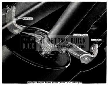
1953 Buick Rear Muffler Clamp
- Remove four front motor mounting lower nuts. (See Fig. 245)
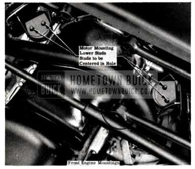
1953 Buick Motor Mounting Lower Studs
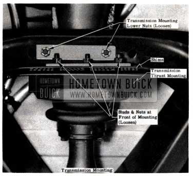
1953 Buick Transmission Mounting Lower Nuts
With all bolts and nuts tightened, the muffler should be centered in the hanger and free to float without binding the insulators.
Make sure that there are no exhaust leaks or muffler, exhaust pipe, or tail pipe interference with the frame.
An out of balance propeller shaft will come in at 65 M.P.H. or over and become worse as speed is increased. When complaints are received regarding roughness which is attributed to propeller shaft out of-balance, the procedure below should be followed.
When satisfied that the engine, transmission and their mountings are in correct condition, and that wheels and tires properly balance, persisting roughness may be the result of axle oil seepage into the propeller shaft, causing apparent shaft unbalance.
This condition, if found, may be corrected by removing the propeller shaft from the pinion, flushing out collected oil with solvent, and draining the propeller shaft tube. The shaft should be in the same location on the pinion as when originally balanced.
Wheels and tires must be balanced and if brake drums seem to have excessive balance weight on them it is advisable to replace drums with a closer balanced drum.
- Check air cleaner for upper half seating properly in oil pan.
- For more detailed information on car and engine noise refer to page 121 of the 1951, 52 BPS Abridged Edition. For wheel and tire balancing refer to Section 60, Page 276 in the 1952 Buick Shop Manual.
Leave A Comment
You must be logged in to post a comment.