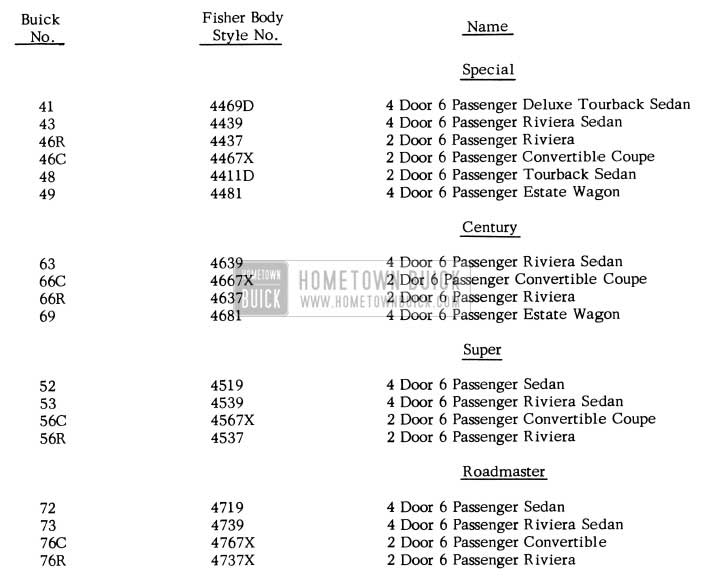
1956 Buick Body Styles
PAINT COLORS
Following is a preliminary list of the DuPont “DUCO” Lacquer stock numbers, and color combination used on 1956 models. As soon as the Du Pont color charts are available they will be attached to a subsequent BPS Bulletin.
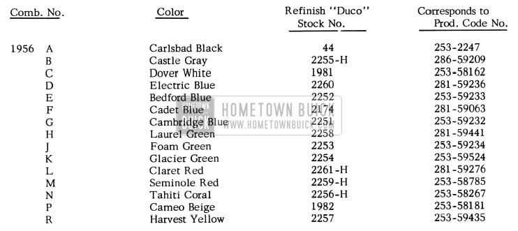
1956 Buick Paint Colors
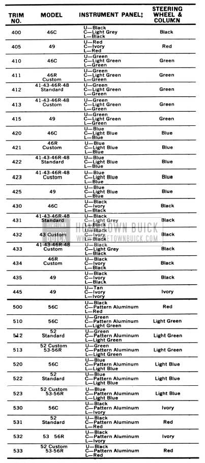
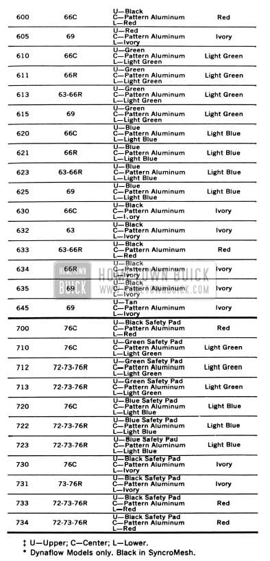
1956 INTERIOR TRIM AND COLOR COMBINATION
Following is a list of the interior trims and color combinations used on the 1956 models. This list also includes the trim number, wheel and mast jacket colors, as well as the duco paint number for the instrument panel colors.
1956 Buick Interior Trim and Color Combinarions
1956 Buick Interior Trim Combinarions
Instrument Panel Duco Paint Numbers are as follows:
Black 253-2247
Red 283-59457
Green 286-58899
Blue 281-59236
Ivory 283-59392
Tan 272-57459
Light Grey 211-57595
Light Green 283-57829
Light Blue 283-57828
WARRANTY ON PAINT
Following is a reprint of Special Red Band Service Letter – Dealer #172 dated February 29, 1956. TO ALL BUICK DEALERS
Special Service Letter – Dealer #1 72
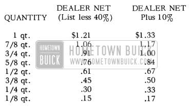
Following is a new schedule of allowances for Duco used in connection with sheet metal and body refinishing under the warranty.
1956 Buick Instrument Panel Paint Numbers
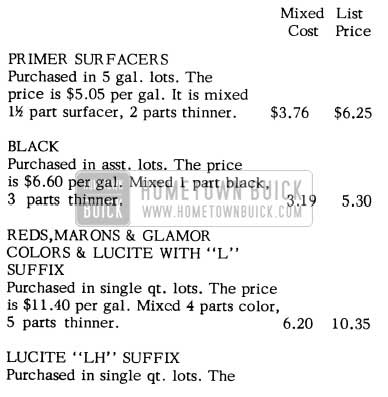
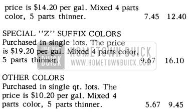
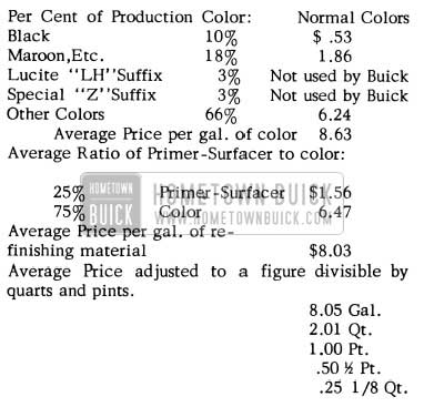
So you will be entirely familiar with the method used in arriving at the average paint cost, the following formula was used in establishing the average selling price of mixed Duco material. Please note that the average price is for mixed Duco and not for color only.
FORMULA FOR ESTABLISHING AVERAGE SELLING PRICE OF MIXED PAINT MATERIAL
1956 Buick Paint Warranty
1956 Buick Paint Material Prices
THINNER
Price in 5 gal. lots. The thinner usually purchased by dealers and recommended by paint manufacturers for general purpose work is $1.65 and thinner used for reduction of color coats is $2 .05 per gal. The latter is used in arriving at the above cost.
The mixed cost was determined by adding the percentage of color and thinner to obtain the cost of a mixed gallon of material. The cost of a mixed gallon was then marked up to give a list price which would allow a 40% discount to dealers.
The average price is determined by taking into consideration the percentages of colors used in production, the ratio of primer-surfacer to color and the above list prices.
1956 Buick Paint Prices
REAR QUARTER OUTER PANEL REPLACEMENTS
1954, 1955, 1956 Buick “40-60” Series
All Styles
When replacing a rear quarter outer panel, it is important that the operations listed below be performed in the sequence shown, to insure adequate protection for the rear quarter area of the body.
PREPARATION OF METAL SURFACES BEFORE INSTALLATION OF REPLACEMENT PANEL
- After removing the rear quarter outer panel, wire brush or sand any rusted areas of the wheelhouse section, baffle plates, and quarter inner panels of the body.
- Treat the bare areas with a metal conditioner. Then prime coat the bare areas.
- Remove the protective coating from the new replacement panel and prime coat the entire inner surface of the panel before installing the panel on the body. This operation is necessary at this time due to the fact it is impossible to prime certain areas of the inner surface of the outer panel after it is installed on the body.
An approved procedure for removing the protective coating is as follows:
- Using mineral spirits, such as kerosene or enamel reducer and clean rags, wipe the coating from the entire panel. Any rust found on the panel must be completely, removed by sanding.
- After cleaning and sanding, a metal conditioner, such as Metal Prep, Deoxidene, R & M Conditioner, etc., should be used to remove all traces of oil and corrosive agents and to act as a rust inhibitor. These metal conditioners also etch the surface of the metal which provides a better bond for the prime coats.
- Two door style quarter panels may have either a deadener pad or a sprayed-on deadener in the area below the quarter windows. Apply a deadener pad on the inner surface of the replacement panel in the same location that the deadener pad or sprayed-on deadener was applied on the original panel.
- Install replacement panel.
- Reprime the areas burned during welding.
APPLICATION OF SEALERS AND UNDERCOATING AFTER INSTALLATION OF REPLACEMENT PANEL
- With a brush, apply medium-bodied sealer, such as 3M Auto Body Sealer or its equivalent, to joint between the quarter outer panel and the inner panel as indicated at “1”in Fig. 113.
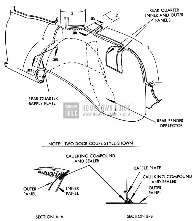
1956 Buick Rear Quarter Outer Panel Replacement
Apply the seal the length of the joint, from the upper comer to the lower comer of the compartment opening.
NOTE: In cases where the gap between the filler strip and quarter outer panel, on coupe and two-door sedan styles, is too large to be effective with medium -bodied sealer, apply body caulking compound to fill in the large gaps; then, brush medium-bodied sealer over the caulking compound.
Undercoating material – 1/2 gal.
Flat Rate Time .5 hr.
REAR SEAT BACK DISENGAGEMENT
PROCEDURE FOR CORRECTING DISENGAGED REAR SEAT BACK MAIN SPRING
If the upper and/or lower ends of the rear seat back main springs disengage from the rear seat back frame, the condition may be corrected by securing the springs to the seat back frame with clips (Gr . 11.419 Part #4562491). The procedure for performing this operation is as follows:
- Remove the rear seat back from body and place on covered bench.
- Re-engage the seat back main springs to the seat back frame as shown at points ”A” in Figure 114 or Figure 115. This operation is performed from the rear side of the cushion. No trim removal is required.
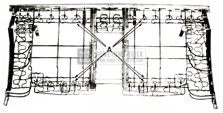
1956 Buick Rear Seat Back with Arm Rest
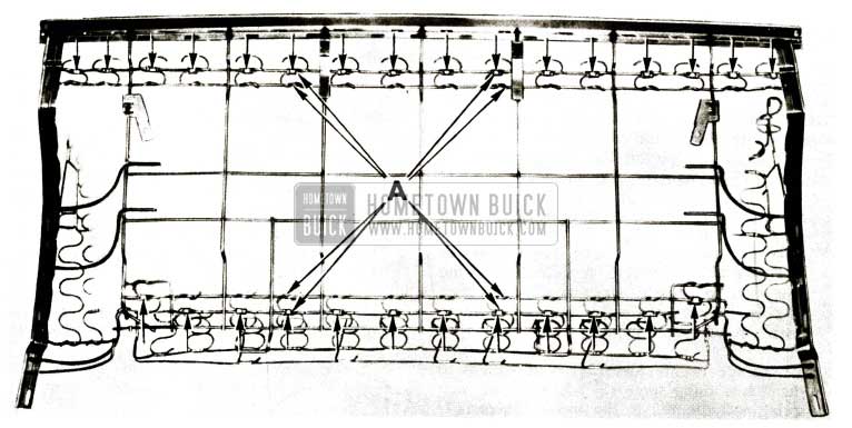
1956 Buick Rear Seat Back
NOTE: A defective main spring unit can be readily recognized by the fact that it does not properly engage the main cross wires as shown at points ”A” in Figure 114 or Figure 115.
- Secure springs to frame with clips as indicated at arrows in Figure 114 or Figure 115.
- Install seat back in body.
The flat rate time to R & R the rear seat back is .3 hr. and .5hr to install the clips.
SQUEAKS IN MECHANICAL SEALING STRIP
1955 Buick – Model 53-73
If a metal-to-metal contact between the side roof rail mechanical sealing strip and the front door ventilator frame and/or rear quarter sealing strip creates a squeaking noise, the condition may be corrected by cementing sponge rubber anti-squeak pads to the mechanical sealing strip at “1” and “2” in Figure 116.
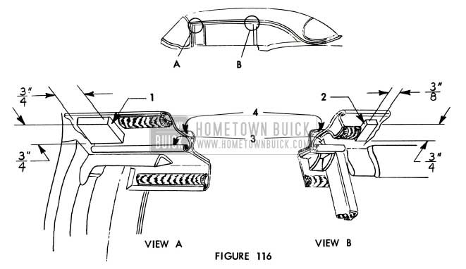
1956 Buick Mechanical Door Sealing Strip
To insure a proper fit of the mechanical sealing strip to the door window, use pads thick enough to protrude 1/16 inch past the flanged edges of the sealing strip.
To ease the opening and closing action of the sealing strip, lubricate sealing strip as follows:
- Using a small brush apply 630 AA lubriplate or its equivalent to the hinge area, indicated at ” 3” below, along entire length of hinge and to the bearing points of the hold open spring assemblies. Work lubricant well into hinge.
- Close and open door several times, then remove excess lubricant.
- Apply a silicone lubricant to the underside of the rubber gasket awning, as indicated at “4” below, along entire length of awning. Clean off any excess lubricant.
REAR SEAT CUSHION DISENGAGEMENT
PROCEDURE FOR CORRECTING DISENGAGED REAR SEAT CUSHION MAIN SPRING UNITS
1956 Buick Models 53-73
If the forward ends of the rear seat cushion main springs disengage from the rear seat cushion frame, the condition may be corrected by securing the springs to the frame with hog rings. Changes have been made to correct the condition in production. The procedure’ for performing this operation is outlined in Figure 117.

1956 Buick Folding Top Hinge
- Remove rear seat cushion from body.
- Re-engage seat cushion main springs as shown in Figure 117. NOTE: A defective spring unit can be readily recognized by the fact that it does not properly engage the main cross wire at “A” Figure 117.
- Secure all twenty-four (24) main springs to the frame using three (3) hog rings on each spring as indicated in the inset, Figure 117. Hog rings must be tight. No trim removal is required.
- Install seat cushion in body.
RELOCATION OF FOLDING TOP HINGE
1956 Convertibles
If the folding top material has been damaged due to chafing at the rear quarter belt finishing molding, the clearance between the molding and side roof rear rail should be checked, and repairs and/or adjustments should be performed as required. The following procedure indicates operations which should be performed before the replacement top is installed.
Although the procedure covers operations to be followed during replacement of a damaged top, it should be noted that it may also be applied as a preventive measure in cases which have not resulted in a damaged top.
- Prior to installation of new folding top trim, check the following two (2) items on both right and left sides to prevent damage to the new material.
- Spacing between belt finishing molding and side roof rear rail. This spacing should be not less than 1/4 inch, as shown in View “A”, Figure 118.
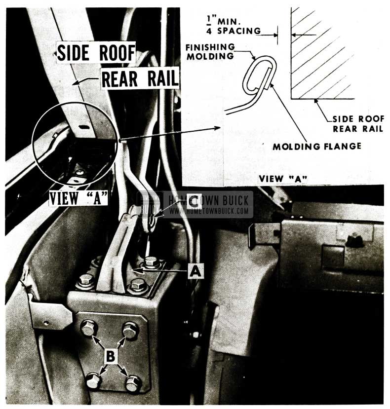
1956 Buick Side Roof Rear Rail
- Loosen the four (4) male hinge attaching bolts and, with no fore or aft movement, shift the male hinge inboard to the limit of the oversize holes in the hinge.
- Loosen the male hinge support bolts “B” and, with no up or down movement, shift the hinge support inboard to the limit of the oversize holes in the support plate.
- Support the side roof rear rail and remove bolt “C”.
- Scribe fore and aft position of male hinge ”A” on support and remove male hinge.
- File the holes in male hinge laterally to obtain the desired movement, and reinstall male hinge.
- Engage male hinge with female hinge and install bolt ”C”.
REAR QUARTER WINDOW UPPER STOP
1956 Models 46R -56R -66R- 76R
If a condition is encountered where the rear quarter window (electrically operated) travels too far forward because the lift arm overrides the upper stop, the stop may be replaced by the stop now used for manually-operated windows (Stop – Rear Quarter Window – Upper, Gr. 11.012 Part #4628952) as described below.
- Raise rear quarter window as far as possible.
- Remove rear seat cushion and back, rear quarter hardware and arm rest assembly. Loosen rear quarter trim assembly sufficiently so that the access hole and upper stop adjusting screw are exposed.
- Check the rear quarter window upper stop to determine whether the window regulator lift arm has overridden it.
- If the lift arm has overridden the upper stop, remove the upper stop and install the new upper stop (Gr. 11.012 Part #4628952) to the inner panel. Adjust the stop to obtain proper alignment of the rear quarter window.
- Check other rear quarter window adjustments.
- Reinstall previously removed parts.
If the lift arm has not overridden the upper stop, then perform normal rear quarter window adjustments to obtain proper operating window.
NOTE: Use caution to disconnect positive battery cable when installing stop to prevent accidental operation of window regulator.
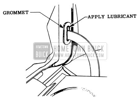
GLOVE BOX DOOR SQUEAKS
All 1956 Buick Styles
If squeaks are encountered at the instrument panel compartment door stop grommet when the instrument panel compartment door is opened or closed, apply a small amount of silicone lubricant to the edge of the hole in the grommet as shown in Figure 119.
1956 Buick Glove Box Door Squeak Repair
DOOR LOCK CONNECTING ROD ADJUSTMENT
1956 Buick 53-73
To assure proper operation of the front and rear door locks, the adjusting nut at the lower end of the front door lock cylinder connecting rod and at the lower end of the front and rear door outside handle push button connecting rod must be properly adjusted .
Whenever work is performed on the front or rear door locking mechanisms, or if a door lock is inoperative, the connecting rod adjustments should be checked and, where required, the adjusting nuts should be adjusted as described below.
To perform adjustments, door trim assembly and inner panel access hole cover must be removed.
FRONT DOOR LOCK CYLINDER CONNECTING ROD ADJUSTMENT
Raise door window and place inside locking knob in unlocked (up) position. Detach lock cylinder connecting rod from lock lever at “A” Fig. 120.
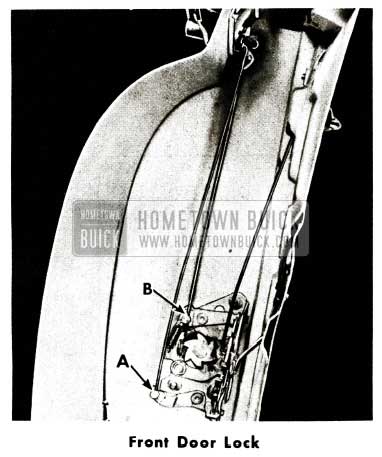
1956 Buick Front Door Lock
Take all play out of lock cylinder connecting rod by pushing rod upward to stop. Line up center line of shank of adjusting nut “A” with center line of hole in lock lever so that shank of adjusting nut slips into hole without interference. Holding shank of adjusting nut in lock lever hole (DO NOT ENGAGE NUT WITH SPRING CLIP), check operation of lock cylinder with both the inside locking knob and with key. If necessary, readjust adjusting nut for proper lock cylinder operation, then install nut into hole until engaged with spring clip.
FRONT AND REAR DOOR PUSH BUTTON CONNECTING ROD ADJUSTMENT
Raise door window and place inside locking knob in unlocked (up) position. Detach connecting rod from lock at “8”, Figure 121.
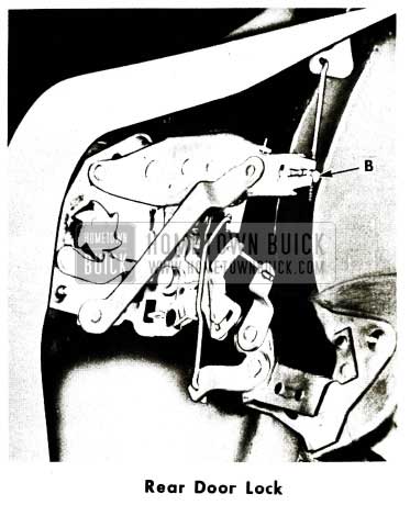
1956 Buick Rear Door Lock
Line up center line of shank of push button connecting rod adjusting nut ” B” with center line of hole in lock lever so that shank of adjusting nut slips into hole without interference.
IMPORTANT: With shank of adjusting nut in lock hole the push button free travel should be from 1/32” to 1 /8” and the lock should lock and unlock from inside locking knob. When nut is properly adjusted install into hole until engaged with spring clip.
NOTE:
- If a push button has more than 1/8” free travel, there may be insufficient travel remaining to trip the lock.
- If a push button has no free travel, it may cause the lock to be inoperative by the push button after once locking the lock with the inside locking knob or with the key.
INOPERATIVE REAR DOOR LOCK
1956 Buick Model 43-63
If the rear door inside locking knob cannot be raised to the “up” position to allow the door to be opened, the condition may be caused by interference between the inside locking control connecting rod, the cloth silencer and the connecting rod attaching clip. The condition may be corrected as follows:
NOTE: A similar correction has been incorporated in production.
- Remove rear door trim pad.
- Cut away the cloth silencer from the inside locking control connecting rod and the inside locking rod.
- Obtain a 1/16″ x 1″ x 6″ deadener strip and cement to door inner panel as shown in Fig.122.
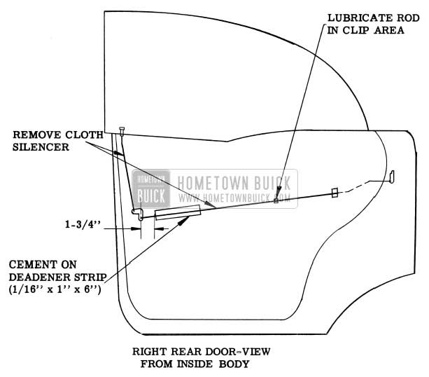
1956 Buick Right Rear Door
LUBRICATION OF SEAT ADJUSTER
1956 Buick Power Operated Seat Adjuster
If the actuator jack screw on a six-way power operated seat adjuster requires lubrication, thoroughly wipe off the old lubricant to remove the dirt which may have accumulated on the jack screw. Then apply Lubriplate #630 AA- W (winter grade) lubricant or its equivalent to the jack screw using caution not to soil trim material. Operate the seat adjuster to the limit of all positions. Then wipe off excess lubricant.
WICKING STAINS
Vicodec Folding Top Material Inner Lining
All 1956 Convertibles
In the event a convertible top is encountered with water stains on the inner lining, the stains can, in most cases; be removed using the following procedure:
- Thoroughly wet the stained area with clear warm water using a sponge as the applicator (avoid rubbing the stained area during the application of the water).
- Slowly run a metal-ended attachment from a tank-type vacuum cleaner over the stained area in order to remove the stains without the necessity of rubbing.
- Allow wetted area to air-dry.
- Repeat operation, if necessary, on any area where the stains persist.
- In the event the stains were caused by wicking due to a waterleak, reseal areas of top where the wicking originated.
WARRANTY ON WINDOW LIFTS
Warranty on Electric Window
Lifts and Motors
The extended warranty coverage of electric window lift motors and gear assembly as covered in BPS 2.375 dated September 15, 1954 applies Only to 1954 Models. The 1955-56 model lifts and motor assembly are covered under the regular standard warranty.
SEAT CHUCKING
Installation of Tensioner Spring on Power Operated Six-Way Seat Adjuster
1956 Models 40-60-50-70
If an excessive seat “chucking” condition is encountered on a power operated six-way seat, the installation of a tensioner spring will effectively reduce the noise and/or “chucking” caused by the movement of the seat adjuster parts at the pivot locations.
The procedure for installing the tensioner spring and attaching parts is outlined below and shown in Figure 123 and 124.
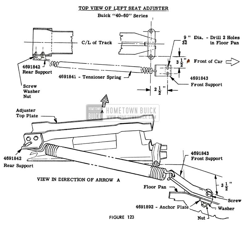
1956 Buick Left Front Seat Adjuster – Series 40-60
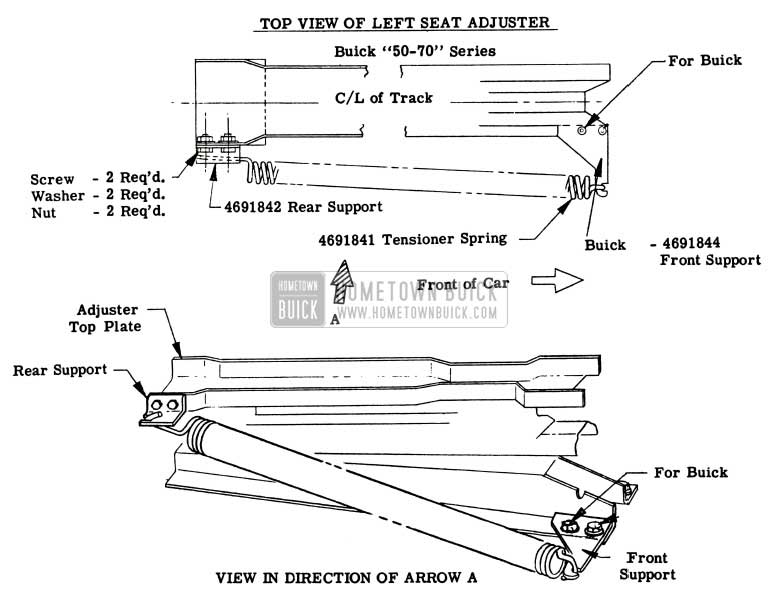
1956 Buick Left Front Seat Adjuster – Series 50-70
One (1) each of the following parts is required to perform this installation:
Gr. No. – Part No. – Description
11.564 – 4691841 – Spring-Seat Adjuster Tensioner – All Series
11.564 – 4691843 – Support-Seat Adj. Tensioner Spring Front – 40-60 Ser.
11.564 – 4691844 – Support-Seat Adj. Tensioner Spring Front 50-70 Ser.
11.564 – 4691842 – Support-Seat Adj. Tensioner Spring Rear 50-70 Ser.
11.564 – 4691892 – Plate-Seat Adj. Tensioner Spring Front Support 40-60 Series
- Operate front seat assembly to the extreme forward position and the rear edge of seat to extreme upward position.
- Remove left lower seat side panel.
- Locate rear support flush with the top and rear edge of left seat adjuster top plate, as shown in Fig.123 for40-60series: and Fig.124: 50-70 series; then clamp support securely to top plate. Using the holes in the rear support as a guide, drill two (2) 9/32 inch diameter holes through seat adjuster top plate; then secure rear support to seat adjuster top plate with two (2) screws, washers and nuts.
- Operate seat rearward, rear edge downward and front edge to extreme upward position. On 40-60 series turn back front floor covering to expose floor pan at tensioner spring front support attaching location. See Fig.l23. Drill two (2) 9/32 inch diameter holes in floor pan at the location shown in Fig.123. then secure front support to floor pan with two (2) screws, washers, anchor plate and attaching nuts as shown in Figure 123.
On 50-70 series cars operate the seat rearward and front edge to extreme upward position (same as 40-60 series); then remove adjuster-to-floor pan front inner attaching bolt. Secure front support on top of adjuster base plate with adjuster attaching bolt as shown in Figure 124.
- Check and if necessary tighten all seat adjuster to floor pan attaching bolts.
- Operate seat to extreme forward and downward position. Engage short hooked end of tensioner spring on the front support as shown in the drawing; then with suitable tool carefully engage rear end of spring on the rear support.
- Install seat side panel and position carpet to original location. NOTE: ln some rare cases, in addition to installing the tensioner spring, it may be necessary to install 3/8 inch I.D. spring washers between the torque tube and seat adjuster links at the pivot locations to provide a front seat which is commercially acceptable from the standpoint of noise and/or motion. It is necessary to remove the seat assembly from the adjusters to install the spring washers.
CAUTION: On any seat equipped with a tensioner spring, be sure to disengage the tensioner spring from the left seat adjuster before performing any service operations which require the removal of the front seat assembly with the adjusters from the body.
ESTATE WAGON REAR SEAT HINGE STUD CHANGE
During 1956 production the Folding Rear Seat Bottom Hinge Stud was changed twice. The first change in this stud was required when the hinge construction was changed from cast iron to stamped steel. When the hinge construction was changed, it was necessary to lengthen the stud slightly for use with the new stamped steel hinge. The first type stud, Gr. 11.380 Part 1176145, for use on cast iron type hinges will still be available as a service item.
After the stamped steel type hinges were used, a second change was made in the stud. This change cancelled the second type stud and released a new round head screw and barrel nut. This change was made to eliminate the possibility of the stud tearing the seat cushion trim and for this reason only the round head screw and barrel nut will be carried for service replacements on cars with the steel stamped type hinge. The stud originally released for use on the steel stamped type hinges, Gr. 11.380 Part 1176146 has now been discontinued and the screw and barrel nut have been released for this use. These parts are Gr. 11.380 Part 1177229, Screw-Round Head Clutch Recess Machine and Gr. 11.380 Part 1177228, Nut-Barrel Rear Seat Cushion Outer Hinge.
RUSTING ROCKER PANEL
We have received a few reports of the rocker panels rusting out on some 1954 models. Upon investigating it was found that the flipper valve in the rocker panels were completely covered with undercoating, thus preventing any water or condensation from draining causing rust conditions. Please instruct the service men responsible for applying undercoating to adhere to the Factory recommendations covering undercoating Buicks as shown on Undercoat Chart.
CONVERTIBLE TOP NOISE
All 1956 Convertible Models
Under certain driving conditions some noise caused by the folding top material slapping against the roof bows may develop. The noise is usually more noticeable in cold weather. This is a standard condition for which we can assume no responsibility. If, however, an owner should desire to have the noise reduced, this may be accomplished by cementing a strip of felt or body cloth on the top side of the front and center roof bows as explained below:
- Obtain a strip of good grade felt, 42 inches long, 1/2 inch wide and 1/16 inch thick for each bow.
NOTE: Two thicknesses of body cloth may be used as a substitute for specified felt in cases where felt is not readily available.
- Operate top to half-raised positon to provide easy access to the roof bows.
- Cement felt strip to top side of the roof bows using a good grade of trim cement.
SQUEAK IN WINDSHIELD AREA
All Models
If a squeak is encountered in the windshield assembly caused by movement of the glass in the rubber channel the following corrective procedure is suggested:
Thoroughly seal the windshield rubber channel to the windshield glass. See Fisher Body Service News for de tailed instructions for this sealing operation.
Lubricate the windshield rubber channel with a silicone lubricant where it contacts the reveal moldings.
It is suggested that the door weatherstrips and shroud hood ledge lacing and bumpers be lubricated with a silicone rubber lubricant whenever a rubber squeak is encountered in the front area of the body.
INCREASING REAR SEAT BACK ANGLE
1956 Buick, Models 53-73
Due to numerous requests, changes have been made in the rear seat back spring .md frame assembly to increase the seat back angle.
If, on an early production body, a customer would like to have the angle of the seat back increased, the lower edge of the seat back may be relocated approximately one inch forward of its original position by installing two (2) wood spacers as follows:
- Remove rear seat back and cushion.
- Bend the two inboard anchor points of the frame and spring assembly rearward 1 1 /4 inches as shown in Figure 125.
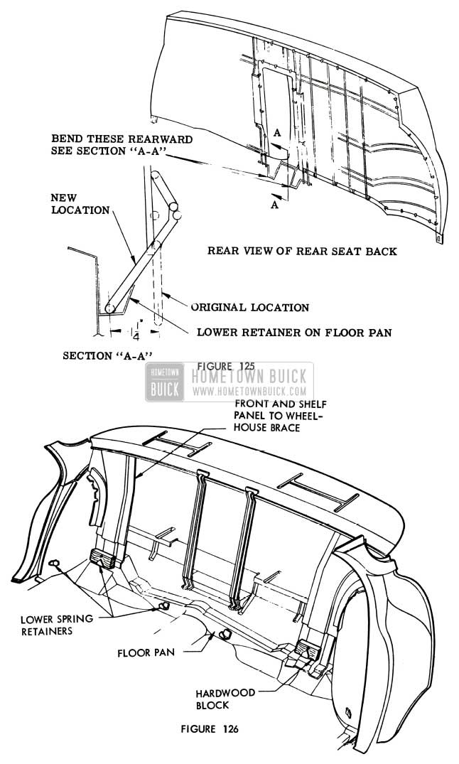
1956 Buick Increasing Rear Seat Back Angle
LOOSE DOOR HANDLE ESCUTCHEON
1956 Buick 53-73
If loose escutcheons are found on the rear door remote control handles on recent production, the condition may be caused by the omission of the escutcheon spring. The condition can be corrected by installing rear door lock remote control handle escutcheon spring, Gr. 10.666 Part #4078002, between the door lock remote control assembly and the door trim pad. Correct ions have been made in production.
QUARTER PANEL INTERCHANGEABILITY
1955-1956 40 and 60 Series
The Parts Department recently released interchangeable rear quarter outer panels for the 1955 and 1956 40-60 series cars. The 1955 and 1956 panels are identical, except the hole for bumper back bars on the 1955 car was changed to a slot for 1956. The interchangeable panel has the slot for back bars and can be used on 1956 cars without any variations. However, when used on a 1955 40 or 60 series car, it is necessary to weld an extra brace between the rear quarter outer panel and the wheelhouse extension to prevent any vibration or rattling of the quarter panel at this location. This brace is the same as used on 1956 production built cars in this location.
The group and part number of the brace is as follows:
Group 12.944 – 4683732 -Brace, Wheelhouse Extension to Quarter Panel.
BINDING INSIDE LOCKING ROD
1956 Buick Models 43 -63
If a condition is encountered where the rear door inside locking knob is hard -operating because the inside locking control rod is binding against the hole in the rear door inner panel reinforcement (at the belt finishing molding), the reinforcement may be reworked as shown in Figure 127. This condition may also cause a bind in the locking mechanism and prevent the rear door from opening when using the remote control handle.
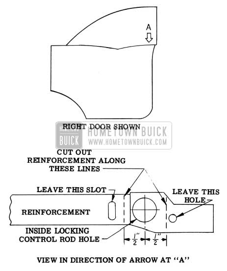
1956 Buick Binding Inside Locking Rod
NOTE: Before reinstalling previously removed parts, check the operation of the locking rod.
TRIM MOULDING CORRECTION
1956
It has been brought to our attention that some instrument panel trim mouldings extend beyond the upper half of the instrument panel, as shown at Point “A” in Fig. 128.
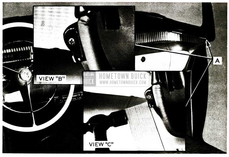
1956 Buick Trim Moulding Correction
View “B” is a close up of the condition. View “C” illustrates how the instrument panel trim moulding may be corrected with the use of a block of wood and a hammer.
With the block of wood held firmly against the end of the moulding, gently tap the block to roll the moulding around the end of the instrument panel.
REAR DOOR STRIKER ADJUSTMENT
Estate Wagons
We have received a few reports that the rear door strikers on Estate Wagons are not adjustable.
In checking with our Engineering Department, they advise that the Ionia Manufacturing Company was using a black sealer on a weld joint near the rear door striker plate which also sealed the striker plate and prevented any movement of the plate.
It is suggested where difficulty of this type is encountered to remove the striker plate and clean all traces of sealer from the plate, so adjustment of the striker plate is made possible.
REAR DOOR OUTER PANEL MOULDINGS
1956 Model 72
The attachment of the rear door outer panel lower front and rear moldings has been revised to provide an improved fit of the moldings to the door outer panel.
On early production the rear door outer panel lower front molding was attached with four (4) snap-in clips and with a screw and clip assembly at the forward end. The removal and installation procedure was similar to the procedure used on 1955 styles and trim assembly removal was not required. On present production the snap-in clip at the rear end of the lower front molding has been replaced with a bolt and clip assembly. To remove the lower front molding, the rear door trim assembly must be removed to obtain access to this bolt and clip assembly.
On early production the rear door outer panel lower rear molding was attached by one screw and clip assembly. On present production a screw and clip assembly has been added at the forward end of the lower rear molding. Both of the screw and clip assemblies now used to attach the lower rear molding are readily accessible without removal of the door trim assembly.
WINDSHIELD WASHER & WIPER TROUBLE DIAGNOSIS
The following procedure has been established to insure proper functioning of the Cam-0-MaticWide Angle wiper and washer as well as to facilitate in locating existing difficulties and their repairs.
There are three separate phases of washer-wiper operation to be tested. It is important to rem ember that each phase be put into proper operation before proceeding with the next phase. Each phase shall be discussed separately in the order as listed below:
- Windshield wiper operation
- Wide angle wiper
- Windshield washer and automatic wipers
Windshield Wiper Operation
There are three major factors affecting wiper operation:
- Bowden wire operation
- Vacuum failures
- Wiper Motor Operation
- The usual difficulties that cause a malfunction of the wiper control bowden wire are pinched or bent wire, wire disconnected at the wiper motor, and the switch is improperly indexed on the instrument panel. If all these points are checked and corrected as needed, we may then proceed to Part B which concerns itself with vacuum failures.
- If vacuum is not present at the wiper motor, it is suggested that by trial error method the point of vacuum difficulty be isolated and corrected. This can be done by operating the engine and checking for vacuum at each coupling between the vacuum source and the wiper motor. See Fig. 129.
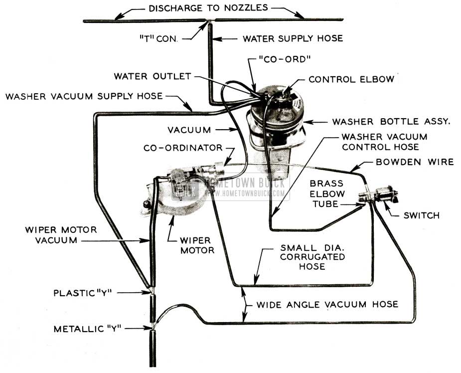
1956 Buick Windshield Wiper Trouble Diagnoses
There are just two (2) hoses that control the “wide angle” wiper operation. If “wide angle” fails, proceed as follows:
The above items are the only things that affect wide angle wiper operation. Following the above steps will cover the necessary items to place the wide angle wiper in proper running order.
Now proceed to test and/or repair windshield washer and automatic wipers.
NOTE: At times, we have found the tang sheared on the wide angle control switch. If the above fails, the switch must be removed and the tang checked.
- Windshield Washer and Automatic Wipers
- Several types of failures are possible in this circuit; however, there are only three (3) major hoses concerned in the functioning of this circuit. First, the washer vacuum control hose from the brass elbow tube on the wiper switch to the “control” tube on washer bottle. NOTE: All hose connections at washer bottle are identified on the cover. Second, the vacuum hose from the washer bottle to coordinator on the wiper motor. Third, the vacuum supply hose on the washer bottle from the plastic “Y” at the engine. See Figure 129
When the washer button is pressed the first action should be water on the windshield. The automatic wipers never function until after the water cycle commences. When water failure is encountered, it may be traced as follows:
- Remove the water supply hose at washer jar and depress washer button. See Fig. 129. The presence of water at bottle outlet indicates trouble in feed lines to windshield discharge nozzles.
- If water is not present at bottle outlet, disconnect vacuum “control” hose at washer bottle and cycle washer manually by momentarily holding finger over opening in “control” elbow. See Figure129. When opening is uncovered, water should come out of outlet in a steady stream for approximately one (1) second. If opening is continued to be left uncovered, water will come out in spurts until opening is recovered or hose reconnected. Presence of water at the outlet indicates washer bottle is good.
- If, when manually cycling the washer and water does not come out of outlet, the bottle assembly is defective and should be replaced. If the bottle checks out to be good, then the trouble is in the washer vacuum control hose leading to the switch or in the switch itself.
- Disconnect control hose from brass elbow at switch and again cycle washer by holding finger over end of hose. Water should come out of bottle water outlet when hose opening is uncovered. If water is not present at bottle outlet, check for obstruction or leak in hose. Presence of water at bottle outlet when cycling switch end of vacuum control hose indicates a defective switch.
NOTE: It is possible for this circuit to check out satisfactorily and still not obtain water through the washer system when switch button is depressed. In this instance, you must change the washer bottle even though it checked satisfactorily. We have found a variation in washer bottle action- -at times a vacuum system will not cycle a good washer bottle. In some cases, it has been found that although a washer bottle would not operate properly in one car, it operated satisfactorily in another. Following the above steps should correct any difficulty encountered in the water cycle.
- Shortly after water cycle commences the automatic windshield wipers should start to operate and continue for approximately 6 strokes after completion of water cycle. If wipers do not operate properly, the source of difficulty may be detected as follows:
- Check for vacuum failure in hose leading from “co-ord” connection at washer bottle to the coordinator on wiper motor. This can be done by disconnecting hose at washer bottle and checking for temporary presence of vacuum at’ ‘co-ord” connection when switch button is momentarily depressed. If vacuum is not present the washer bottle is defective.
- Other possible caused of inoperative automatic wipers are:
- Defective coordinator
- Defective hose
- If wipers operate too long or will not shut off automatically, the possible causes are:
- Improper screw adjustment. See Figure 130.
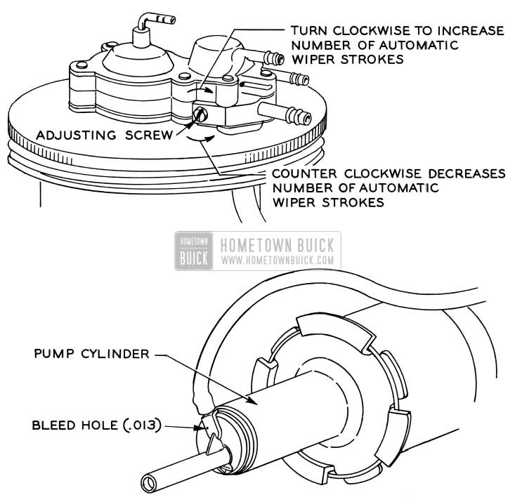
1956 Buick Windshield Wiper Stroke Adjustment
NOTE: Turning adjusting screw clockwise with screw driver will make wipers operate longer; counterclockwise decreases the number of strokes.
NOTE: Should you accidentally press washer button in freezing weather when washer lines are frozen, blades will operate for 1 minute before stopping.
WINDSHIELD BREAKAGE
1956
Several reports have been received concerning windshield breakage. This windshield breakage has been traced to the left hand defroster outlet being bent out of position to such an extent that it bears heavily against the left windshield wiper transmission, resulting in shroud distortion. The resulting distortion at the transmission has caused the windshield to break or crack.
It is recommended that when mechanics are removing and replacing the speedometer that care be taken not to bend the defroster outlet as described above.
CLIP FOR WINDOW GUIDE PAD
1956 Models 43-53-63-73
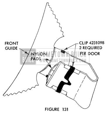
If a rattle develops in the rear doors on the above style bodies, it may be caused by a rear door window front guide nylon pad becoming disengaged. To provide positive attachment of the nylon pads to the guide, a Rear Door Window Front Guide Nylon Pad Retaining Clip (Group 10. 766, Part #4231098) may be installed. The procedure for installing these clips is outlined below.
- Remove rear door window front guide.
- Attach retaining clips to nylon pads on front guide as shown in Figure 131.
1956 Buick Clip for Window Guide Pad
PAINT ON NEW CARS
Following is a reprint of Special Red Band Service Letter, Dealer No. 161, dated November 10, 1955, relative to Paint on New Cars.
A very important responsibility of Buick Dealer Service Managers is to see that every new car is delivered to the purchaser in a good commercially -acceptable condition.
At this season of the year when all dealers are delivering 1956 model cars, it is particularly important that all new cars be carefully inspected and the unsatisfactory paint be touched up or panels refinished before delivery.
A recent survey of owner complaints indicates that a number of new car purchasers are not satisfied with the condition of the paint on their new cars when delivered to them. Many owners state that they are told the paint will be taken care of at the 2,000 mile inspection.
An analysis of AFA’s submitted for thin paint indicates that almost 60% of the refinishing jobs are performed on owners’ cars after delivery. This would indicate that the purchasers of these cars were not satisfied with the condition of the paint on their cars at the time of delivery, and, therefore, lost much of their new car enthusiasm.
Another undesirable feature of this is that once the owner finds a spot where the paint is thin or rubbed through, he immediately inspects the entire automobile closely to find out how many more places he can find, and he usually finds them or at least thinks he has found more.
It is not necessary to secure Zone Office approval to correct unsatisfactory paint on individual panels, if that work is done on new cars before they are de livered to the purchaser.
If it is not done before delivery, Zone Office approval is necessary before proceding with the work.
This policy applies only to spot and individual panel refinishing. In cases where it is felt that the entire car requires refinishing, Zone Office approval must be obtained.
To put this policy in effect, we suggest that every dealer wash and inspect each new car as soon as it is received. The car should then be inspected by a designated individual who is familiar with commercially standard paint. Ordinarily this man is not one of the painters. After the car has been inspected, and if sub-standard paint is found, an order should be written specifying exactly what painting is to be done to panels or portions of panels.
AFA’s will not be accepted for the following conditions:
- Removal of minor surface blemishes or scratches in the finish which can be polished out.
- Minor spot and touch- up work found necessary.
- Rubbed through spots caused by careless workmanship in the dealership while the car is being polished for delivery. These are the dealer’s responsibility.
- Damage after delivery caused by flying gravel, excessive polishing or lack of care by the owner.
AFA’s submitted for paint work should give a clear description of the conditions which required the refinishing. If spots on the panel actually are not covered sufficiently and primer is showing through, the description should be “thin paint” and the exact location given on the AFA.
If the paint appears to have been put on over dirty metal, that information should be shown on the AFA.
If the refinishing was done because abnormal file marks on the metal were visible, that information should be shown on the AFA.
It is difficult for anyone to justify a paint AF A when the description indicates the paint was thin and car had been driven 4000 miles. If the paint was thin when the car left the factory, it should have been taken care of before the car was delivered.
The intent of this policy is to aid all dealers in delivering new cars to purchasers in tip-top condition, and prevent possible complaints and dissatisfaction. Strict adherence to this policy will accomplish that purpose.
WATER LEAKS AT FOLDING TOP
All 1955 Convertible Styles
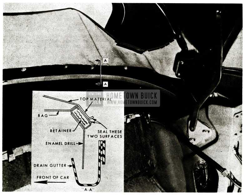
If water wicking is encountered at the folding top compartment bag or at the inner surface of the folding top material along the back and/or rear quarter belt lines, the edges of the bag and top material should be sealed along the rear trim stick .
If waterleaks are encountered because of water by-passing the folding top compartment drain gutter, a piece of enamel drill material should be cemented to the trim stick retainer to deflect the water into the drain gutter.
The following procedure gives the corrective action for the above conditions.
- Remove rear seat cushion and back, and remove folding top compartment side trim assemblies (arm rests).
- Detach the folding top compartment bag from the rear seat back panel to gain access to the trim stick retainer attaching screw.
- Remove the trim stick retainer attaching screws and raise the bottom section of the top from the body.
- If there is wicking of the top material or the bag, seal the trimmed edges of the material with an approved convertible top sealer as shown in Fig. 132.
1956 Buick Convertible Folding Top Water Leak Repair
The inside surface of the top material should be waterproofed along the entire length of the trimmed edge. Be sure that the edges of the stay pad along the retainer are thoroughly sealed.
NOTE: If there is tape on the trim sticks and there is wicking of the material, the tape should be trimmed so that edge of the material is accessible. It is not necessary to re-apply this tape after the above sealing operation is performed.
- If water overshoots the gutter below the bottom edge of the folding top, cement the cotton side of a piece of enamel drill material to the inside (metal surface of the retainers with an approved weatherstrip cement. The top edge of the enamel drill material should not extend above the top edge of the retainers, and should be of sufficient width to extend into the gutter for the entire length of the gutter. (See step “c” in Figure 132.)
- Punch holes in the enamel drill material at screw locations and install trim stick retainer attaching screws securely.
- Trim enamel drill material along bottom edge so that the drill material will extend about half-way into the gutter and does not obstruct the drain holes at the forward ends of the gutter.
- Reinstall previously removed parts.
MOLDING & TRIM INTERFERENCE
All 1956 Buick 50-70 Series
If interference between the front door trim assembly and the instrument panel end molding has a tendency to damage the trim assembly, the condition may be corrected by adjusting the trim assembly rearward as follows:
- Remove front door garnish molding, ventilator window handle and door inside handle.
- Remove trim assembly attaching screws and loosen trim assembly attaching nails from nail slots in door inner panel. Do not completely disengage nails.
- Move trim assembly slightly rearward to obtain necessary clearance at the instrument panel. Limit rearward adjustment to a maximum of 1/8 inch. An excessive rearward adjustment may cause the trim assembly inside handle holes to show from under their escutcheons and/or the rear edge of the trim assembly may interfere with the door lock pillar.
- Using holes at lower corners of trim assembly as a guide, punch new screw attaching holes in inner panel.
- Seal the original attaching screw holes.
- Install trim assembly attaching screws.
- Using a mallet, secure the trim assembly nails along front and rear edge.
- Re-install garnish molding, ventilator window handle and door inside handle.
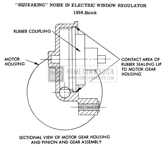
SQUEAKING NOISE IN WINDOW REGULATOR
If a “squeaking” noise is encountered when an electric window regulator is operated, the condition may be caused by insufficient lubrication of the motor rubber coupling sealing lip where it contacts the motor gear housing.
The “squeaking” noise may be eliminated by lubricating the sealing lip at the contact area as shown in Figure 133.
1956 Buick Electric Window Regulator Noise Repair
A silicone rubber lubricant or lubricant from the gear housing should be used. On some styles the sealing lip is accessible for lubrication through the door inner panel access hole. On other styles the window regulator must be removed to obtain access to the sealing lip. See Fisher Body Service News for removal and installation procedures.
NOTE: Improperly lubricated window guides and cam channels will also cause a noisy operating window. Carefully check these parts for proper lubrication.
ADHESIVE TO COATED FABRIC AND LEATHER TRIM
review of the adhesives recommended for use on trim materials indicates that it is necessary to revise our recommendations as follows:
Use 3M Super Weatherstrip Adhesive (neoprene) or its equivalent to attach all coated fabric trim (imitation leather) and all genuine leather trim materials. This procedure is required to eliminate bleeding and staining when cementing coated fabrics or genuine leathers.
Use 3M Trim Cement or its equivalent on all other trim materials, such as, upholstery cloth, cloth headlining, floor carpet, etc. (This concurs with the past recommended procedure.)
NOISE IN REAR DOOR LOCK
1956 Buick Models 53-73
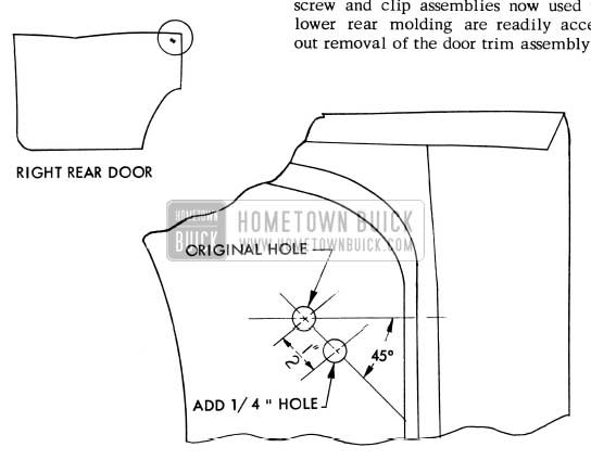
If an objectionable noise occurs when a rear door is closed on a body that has a round rear door lock pillar upper bumper, the condition may be caused by the door lock rotary bolt contacting the back facing of the door lock striker. As the contact between the rotary bolt and the back facing of the striker is a result of door over-travel, the condition may be corrected by replacing the round bumper with a thicker, oblong bumper as follows:
- Remove the round rear door lock pillar upper bumper.
- Locate and drill a 1/4″ hole at a point 1 /2″ from center of original hole and on an angle 45° below and rearward of original hole. See Figure 134.
1956 Buick Rear Door Lock Noise Repair
REAR DOOR OUTER PANEL MOLDINGS INSTALLATION
1956 Buick Model 72
The installation of the rear door outer panel lower front and rear moldings has been revised to provide an improved fit of the moldings to the door outer panel.
On early production jobs the rear door outer panel lower front molding was attached with four (4) snap,-in clips and with a screw and clip assembly at the forward end. The removal and installation procedure was similar to the procedure used on 1955 styles and trim assembly removal was not required. On present production jobs the snap-in clip at the rear end of the lower front molding has been replaced with a bolt and clip assembly. To remove the lower front molding, the rear door trim assembly must be removed to obtain access to this bolt and clip assembly.
On early production jobs the rear door outer panel lower rear molding was attached by one screw and clip assembly. On present production jobs a screw and clip assembly has been added at the forward end of the lower rear molding. Both of the screw and clip assemblies now used to attach the lower rear molding are readily accessible without removal of the door trim assembly.
INTERFERENCE BETWEEN WEATHERSTRIPS
1956 Buick Model 43-63-53-73
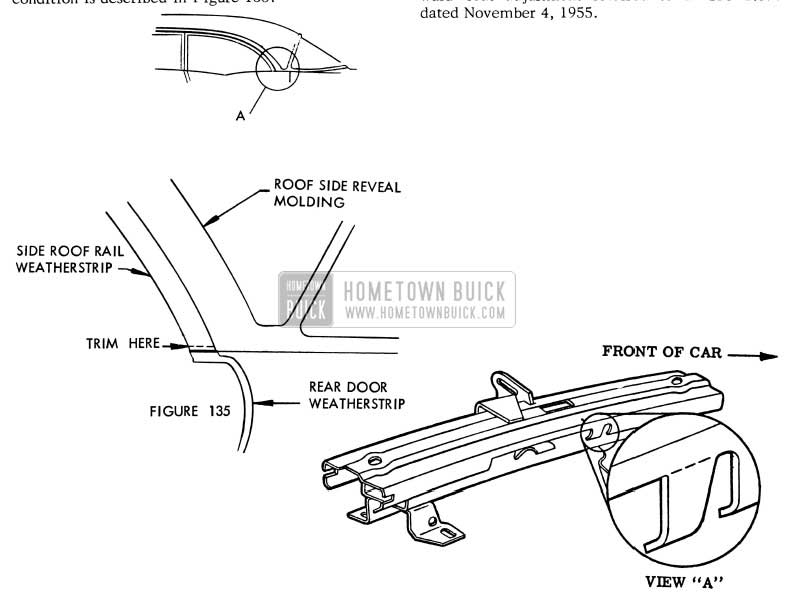
If interference between the side roof rail weatherstrip and the rear door weatherstrip has a tendency to damage either or both of the weatherstrips and the condition cannot be corrected by alignment of the door, the condition may be eliminated by trimming stock off the rear end of the side roof rail weatherstrip. Use caution to trim off only the stock necessary to prevent damage and yet maintain a proper weather seal.
Changes have been made to correct the condition in production. The corrective action for this condition is described in Figure 135.
1956 Buick Interference between Weatherstrips
ADDITIONAL MANUAL SEAT ADJUSTMENT
An additional 5/8 inch rearward travel of the front seat assembly can be obtained by removing the tab, shown in View “A”, Fig.136, from the upper track of the seat adjuster. To remove tab, remove lower seat side panel and with suitable tool bend tab until it breaks off the upper track of the seat adjuster. Perform the same operation on the left adjuster. NOTE: The left adjuster tab is located on the inner face of the adjuster but it can be removed by reaching under the seat assembly.
The above information will supersede the rearward seat adjustment referred to in BPS 2.396 dated November 4, 1955.
WIND NOISE AT WINDSHIELD
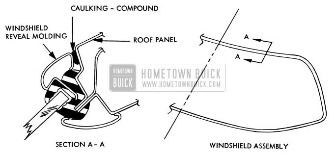
1956 Models, Except Convertibles and Models 52 & 72
If an objectionable wind noise is caused by a gap (usually 1/16″ or larger) between the windshield upper and/or side reveal moldings and the roof panel, the condition may be eliminated by filling the gap with body caulking-compound as shown in Figure 137.
1956 Buick Windshield Noise Elimination
Leave A Comment
You must be logged in to post a comment.