1956 REAR AXLE CHANGE
The following is a reprint of Special Service Letter – Dealer No. 179, dated May 22, 1956.
Because of many rear axle differential case and related parts changes that were made up until the present time and changes that will go into effect within a month or so, we have prepared this bulletin to describe these changes and to list the service procedures which vary according to each change. The first portion of this bulletin will, therefore, describe all these differential changes that have been or will be made while the second portion will be devoted to service information and tool changes.
DIFFERENTIAL CASE AND RELATED PARTS CHANGES
- The original differential case, Gr. 5.510 Part #1168702 (without side gear thrust washer) was replaced by a new case package (#1392756) which was machined to accept two (2) side gear thrust washers Gr. 5.543 Part #1174391, which were included in the package. At the same time the side gear thrust washers went into production, side gear hub length was increased from .460″ to .520″. To further improve the operation of case package 1392756, the Parts Department released for service Gr. 5.510 Part #1392855, package differential oil baffles and felt insert washers. This package includes two (2) steel differential oil baffles and two (2) felt insert washers, which are to be installed in casting recess as shown in Figure 35.
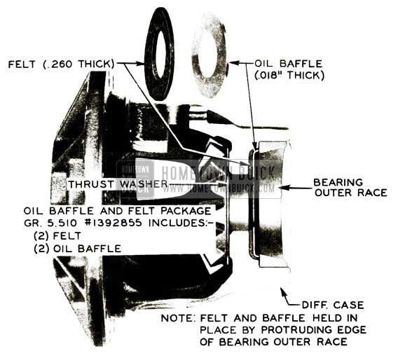
1956 Buick Rear Axle Oil Baffle Installation-First Type
(NOTE: One (1) baffle and felt insert washer for each side gear.) . You will note that the side bearing outer race compresses the felt and oil baffle and holds them in position. The addition of the felt and oil baffle will insure lubrication of the side gears where they rotate in the case and help prevent wear which contributes to the clunking noise.
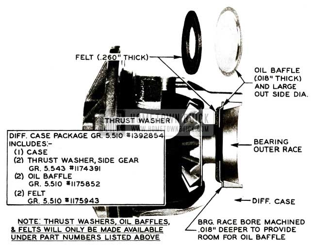
- Similar felt washer and oil baffle changes went into production approximately May 3, 1956. This production arrangement is shown in Figure 36.
1956 Buick Rear Axle Oil Baffle Installation-Second Type
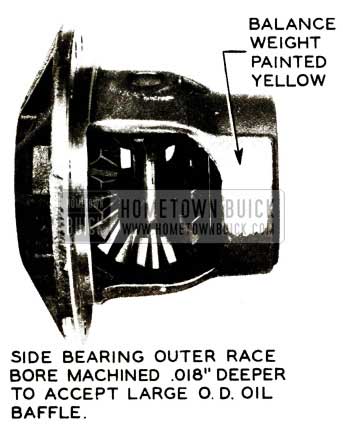
You will note that thickness of felt washer in Figures 35 and 36 is .260” while felt washer in Figure 39 is .180″. Also note in Figure 36 that oil baffle (.018″ thickness) has a large O.D. and is sandwiched between differential case and side bearing outer race. To facilitate this change without affecting selection of side bearing preload shims, it was necessary to machine the differential case side bearing outer race bore .018” deeper. All cases shown in Figure 36 will be identified by a yellow daub of paint on case counter balance weight as shown in Figure 37.
1956 Buick Side Bearing
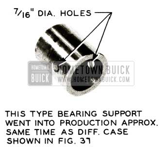
In addition to this change, differential bearing supports equipped with two (2) 7/16″ dia. holes also went into production approximately May 3, 1956. See Figure 38.
1956 Buick Bearing Support
NOTE: The holes were added to facilitate use of new type support puller which will be described later.
Stock of case package #1392756 has been exhausted and in order to fill orders on hand a new case package has been released. The part number of this case package is Gr. 5.510 Part #1392854, and will include one (1) differential case which is machined .018″ deeper to accept the production type oil baffle (shown in Figure 36), two(2) differential side gear thrust washers, two (2) oil baffles and two (2) side gear felt insert washers. NOTE: Side gear thrust washers, oil baffles and felt insert washers will only be made available separately under the following part numbers:
Gr. 5.543 – #1174391 Washer – Differential Side Gear (2)
Gr. 5.510 – #1175852 Baffle – Differential oil (2) Gr. 5.510 – #1175943 Felt insert washer – side gear baffle (.260″ thick) (2)
- The following case change will go into production approximately the last week in May and will be made available to supersede the previously described changes. The change in this case will consist of increasing the differential side bearing surface width in case .100”. At the same time, side gear hub length will be increased .100″ and thickness of felt washer decreased to .180″. See Figure 39.
1956 Buick Rear Axle Oil Baffle Installation-Third Type
The service differential case package comprised of these new parts will be available under Gr. 5.510
Part #1392843 and will include the following:
(1) Case
(2) Gr. 5.528 – #1175848 Gear – Differential Side
(2) Gr. 5.537 Jf1175847 Support Differential bearing
(2) Gr. 5.543 – #1174391 Washer – Differential Side Gear Thrust
(2) Gr. 5.510 – #1175852 -Oil Baffle
(2) Gr. 5.510 – #1175942 – FeltThis package will be supplied for all replacements of case 1168702 and packages 1392756 and 1392854 as soon as stock is available.
NOTE: The above side gears and bearing supports will be available through the Parts Department and will replace those previously used; therefore, it is important that whenever installing these new side gears in a case previously equipped with side gears having shorter hub length, it is advisable to also install bearing supports equipped with holes to facilitate subsequent removal if it should become necessary.
Summary: Case packages 1392756, 1392854, and 1392843 (when available) used with felt washers and oil baffles, will effectively reduce differential case bore wear at the side gears which results in a clunking noise. Do not hesitate to use whichever package that may be available whenever a “clunk” complaint is encountered.
TOOL CHANGES AND SERVICE INFORMATION
Removal of Differential Case Side Bearing Supports, Using Puller J -6199
NOTE: Due to the fact that two (2) different differential bearing supports, both of which are dimensionally the same, have been used in our 1956 rear axle, a different puller for each type is required. The only difference between these two supports is that one has two (2) 7/16″ dia. holes for use with a new pin type puller described in Step 2 below. The bearing support without holes can be removed with the original puller J -6199 which has been reworked as shown in Figure 40; however, in some instances further modification of puller J -6199 will be necessary as described in sub. par. (b) below.
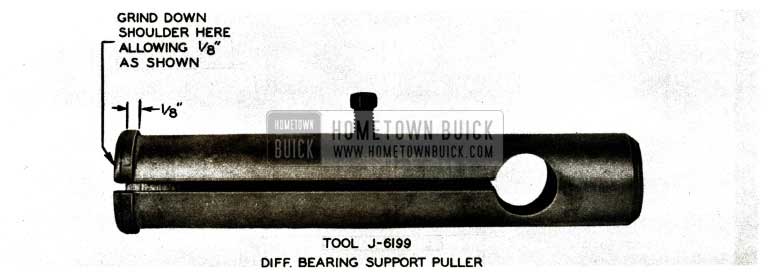
1956 Buick Bearing Support Puller
- If puller J -6199 has been reworked as shown in Figure 40, it will work satisfactorily for removing supports from cases equipped with type oil baffle shown in Figure 35.
- If case is equipped with large O.D. oil baffle as shown in Figures 36 and 39, it will be necessary to permanently force oil baffle away from end of bearing support as far as possible to provide room for J -6199 puller jaws. In those instances where puller jaws will not slide into pulling position, it is suggested that reworked puller J -6199 be further modified by grinding chamfer on end of puller. See Figure 41.
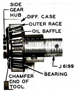
1956 Buick Differential Side Gear Hub
The added chamfer should permit the puller to be expanded when positioned between oil baffle and end of bearing support as shown in Figure 41. It is recommended that this chamfer not be added unless absolutely necessary as it will greatly weaken the tool and may result in tool breakage.
Removal of Differential Case Side Bearing Support; Using New Puller J-6553.
Differential Bearing Support Puller J- 6553 shown in Figure 42 is a new tool which is designed to be used with differential bearing supports having two (2) 7/16″ dia. holes.
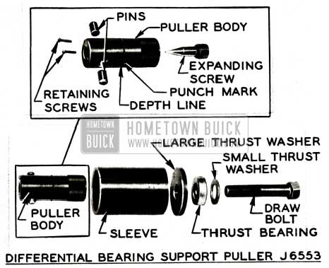
1956 Buick Differential Bearing Support Puller J6553
Bearing supports with these holes went into production approximately the same time as differential case shown in Figure 36 (case identified by yellow paint on counterbalance weight as shown in Figure 37). Puller J -6553 consists of the puller body, pins, retaining screws, and expanding screw. The puller body has a punchmark and line inscribed on it to aid in locating proper depth of puller and inserting pins in bearing support holes. The pins are actuated by turning the expanding screw with a screwdriver.
The following procedure describes the application of the new pin type differential bearing support puller J -6553.
- Using a screwdriver turn expanding screw in puller body in counterclockwise direction to retract pins, then insert puller body into differential bearing support until reference line on tool is flush with end of support and punch mark is in general direction of hole in bearing support. See Figure 43, View A.
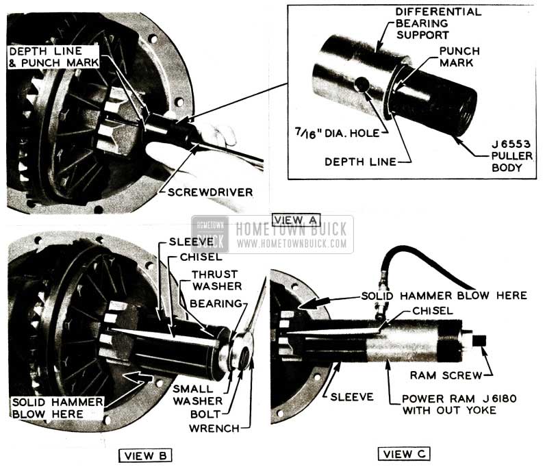
1956 Buick Bearing Support Installation
- Expand pins slight amount by turning expanding screw with screwdriver in clockwise direction until light drag on pins is felt, then move tool as required to engage pins with holes in support. Fully expand pins.
- Wedge carrier pedestal open with chisel. See Figure 43, Views Band C.
- Apply pulling force to bearing support puller by using either of the following methods:
- Place sleeve over puller and install draw bolt with large thrust washer, thrust bearing and small washer in sequence shown in Figure 43, View B; then thread draw bolt in tapped hole in puller body.
(1a) Using suitable wrench apply reasonable amount of torque to draw bolt; then strike carrier pedestal with solid hammer blow in direction of heavy arrows as shown in Figure 43, View B.
- Place sleeve over puller and install hydraulic ram screw as shown in Figure 43, View C.
(2a) Place reasonable load on ram, then strike carrier pedestals with solid hammer blow in direction of heavy arrows as shown in Figure 43, View C.
- Removal of Differential Case Side Bearing Outer Race
- If it should become necessary to remove the differential case side bearing outer race from a case equipped with oil baffles and felt insert washers Package Gr. 5.510 Part #1392855 (shown in Figure 35) it will be necessary to provide working clearance for race remover J -6269 by deforming the oil baffles with a pair of pliers and removing it and the felt washer. Differential bearing outer race remover J -6269 may be used in the regular manner as shown in Figure 6-15 in the 1956 Shop Manual.
- If it should become necessary to remove the differential case side bearing outer race from a case which has the large O.D. oil baffle mounted in race bore as shown in Figure 36 and 39, a new bearing outer race puller J -6552 will effectively remove the race with a minimum amount of time and effort. This new tool will work satisfactorily on all differential cases regardless of production changes; therefore, it is strongly recommended that the new puller be purchased and used because it makes the job much easier and faster. Differential side bearing outer race puller J -6552 components are shown in Figure 44, View A. View B in Figure 44 shows puller in position to remove bearing race.
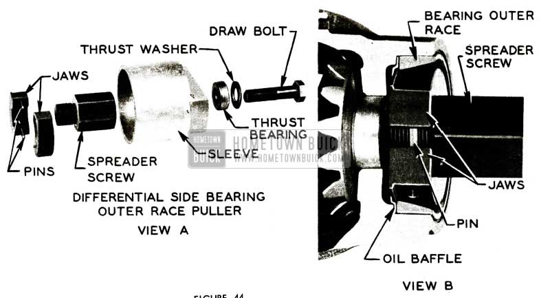
1956 Buick Differential Side Bearing Outer Race Puller
To install puller merely insert two puller jaw halves in position as shown in Figure 45, View A, making certain that pulling edge of each jaw is under bearing race.
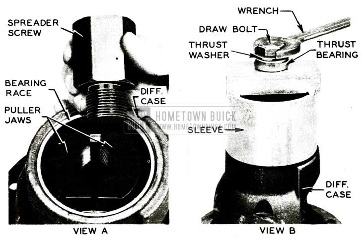
1956 Buick Differential Case
Thread spreader screw in puller jaws until it is fully seated against both jaws and finger tight as shown in Figure 44, View B, then install sleeve over puller with draw bolt as illustrated in Figure 45, View B. Turn draw bolt with suitable wrench to remove bearing race.
- In the event of an emergency, if it should become necessary to remove side bearing outer race from either case assembly shown in Figures 36 and 39 and new puller J -6552 is not available, proceed as follows:
- Remove as much of oil baffle as possible, using suitable cold chisel and hammer as shown in Figure 46, View A.
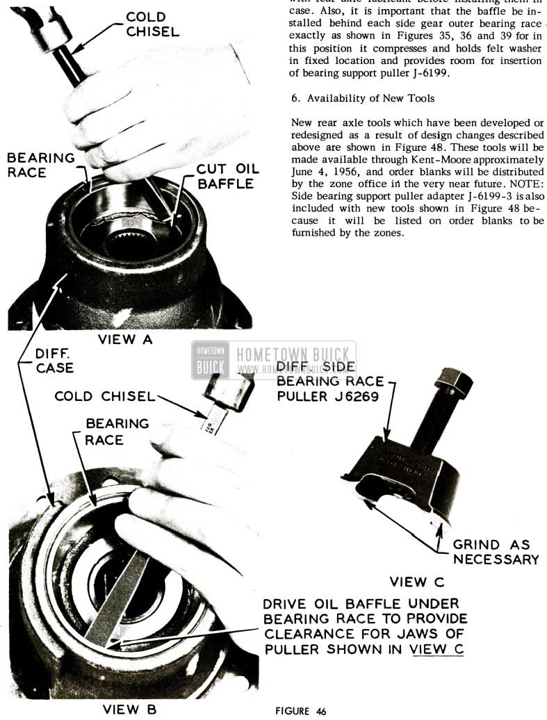
1956 Buick Differential Oil Baffle
- After center portion of baffle has been removed, drive two (2) sections of remaining baffle under bearing race as far as possible to accommodate width of J -6269 puller jaws. See Figure 46, View B.
- Grind tool J -6269 shown in Figure 46, View C until jaws will slip under bearing race. CAUTION: Do not grind any more metal away from puller than is necessary because tool breakage may result. The bearing race may then be removed with this reworked puller in the normal manner as shown in Figure 6-15 in the 1956 Shop Manual.
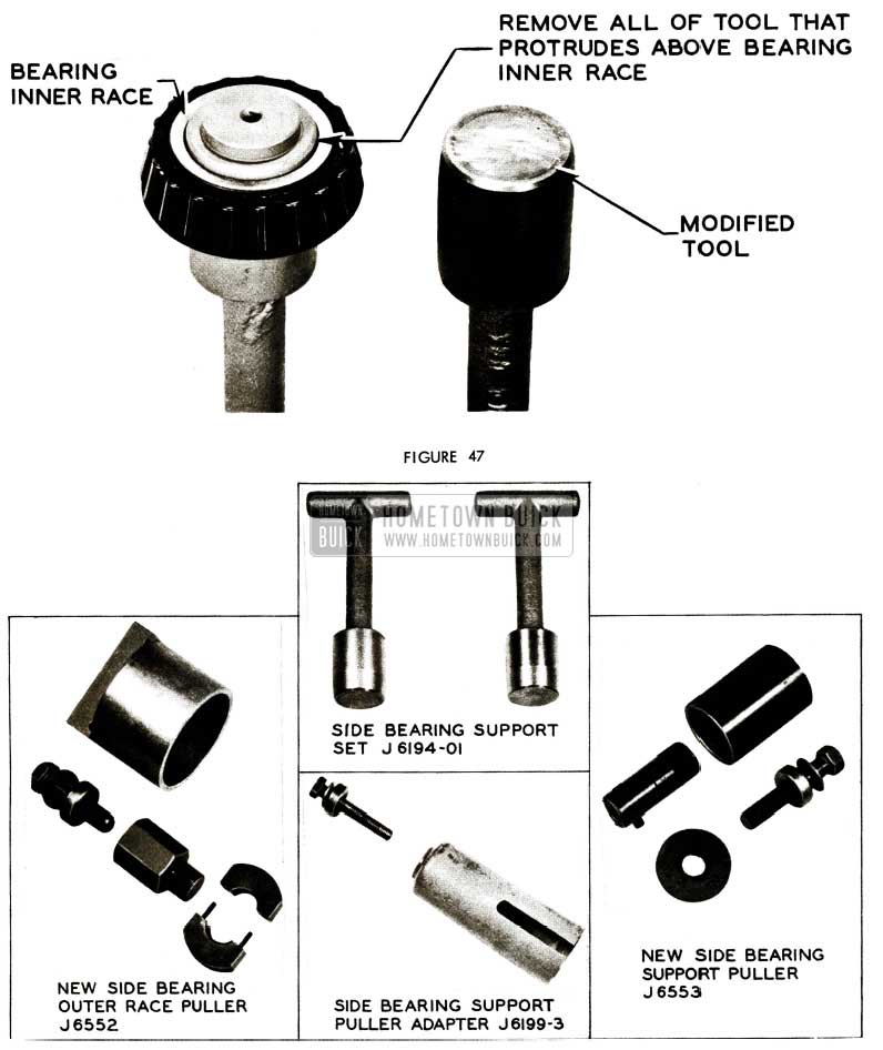
- Differential Side Bearing Support Tool J -6194
During differential side bearing shimming operation on reassembly of rear axle, this tool cannot be fully seated in side bearing because of interference with newly added oil baffle. To overcome this difficulty, it will be necessary to rework the tool by placing it in a side bearing, as shown in Figure 47 and then removing that portion of tool which extends beyond inner bearing race. It is suggested that the hardened surface first be ground off before attempting remachining tool to reduce length. The reworked tool is also shown in Figure 47.
1956 Buick Side Bearing Support Tools
Installation of Oil Baffles and Felt Insert Washers
It is important to thoroughly saturate felt washers with rear axle lubricant before installing them in case. Also, it is important that the baffle be installed behind each side gear outer bearing race exactly as shown in Figures 35, 36 and 39 for in this position it compresses and holds felt washer in fixed location and provides room for insertion of bearing support puller J-6199.
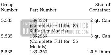
Availability of New Tools
New rear axle tools which have been developed or redesigned as a result of design changes described above are shown in Figure 48. These tools will be made available through Kent-Moore approximately June 4, 1956, and order blanks will be distributed by the zone office in the very near future. NOTE: Side bearing support puller adapter J-6199-3 is also included with new tools shown in Figure 48 because it will be listed on order blanks to be furnished by the zones.
REAR AXLE LUBRICANT
BUICK FACTORY ENGINEERED REAR AXLE LUBRICANT
We are quoting the following from Buick Parts Product Information bulletin (BPPI) dated July 2, 1956, which covers the use of Buick Hypoid gear lubricant.
“The Rear Axle Lubricant furnished with each replacement Ring and Pinion Gear Set is the most satisfactory type that the Buick Engineering Department has found which will give adequate lubrication protection to the Buick Rear Axle under all the conditions encountered in service. This lubricant is used in all new Buicks and is available as follows:
1956 Buick Rear Axle Lubricant
The lubricant is compounded by the supplier to exacting specifications which have been determined by Buick Engineers, and each lot is tested at Buick before it can be used for either production or service.
“This Rear Axle Lubricant is a Special Extreme Pressure Hypoid Gear Lubricant of the Lead Soap Active Sulphur type, compounded to General Motors Specifications No. 4655M, and exhaustive tests have shown it to be the best known for the conditions encountered in the Buick axle. These tests have shown that some brands of Multi-Purpose Gear Lubricants available in the field, while satisfactory for maintaining proper level, are often unsatisfactory for a complete fill, either before or after the gears have been run. These Gear Lubricants do not furnish the protection against scoring afforded by the Buick Rear Axle Lubricant and, as mentioned in the Shop Manual, should not be used except for adding purposes. It is recommended that whenever a complete fill is required, either when a new Gear Set has been installed or when a Rear Axle in service is repaired, that Buick Factory Engineered Rear Axle Lubricant be used.
”The 120 pound drum of Rear Axle Lubricant Group 5.535, Part No. 1392360, provides a larger sized container for use in dealerships where a large amount of Rear Axle servicing and lubricare work is done. The new container is more convenient to order and stock and will give you assurance that the recommended Rear Axle Lubricant is being used.”
NOTE: The 120# drum of Rear Axle Lubricant reduces the price of a complete fill to approximately 96 cents, as compared to a cost of $1.47 when the 3 qt. can is used. There are approximately 20 complete fills in each 120# drum.
REAR AXLE SHIMS & SPACERS
1956 Models
The following is a list of the shims and spacers which are used while performing the three Rear Axle Carrier Adjustments:
Pinion Bearing Preload Adjustment: Rear Axle Pinion Bearing Preload Spacers – Group No. 5.484
Part No. – Thickness
1169104 .200
1169105 .201
1169106 .202
1169107 .203
1169108 .204
1169109 .205
1169110 .206
1169385 .207
1169386 .208
1169387 .209
1169388 .210
1169389 .220
1170158 .230
1170159 .240
1170160 .250
1170161 .260Pinion Depth Adjustment
While Engineering has released the odd size pinion shims (even part numbers), none have been produced. Only even size pinion shims are now available through the Parts Department.
This makes it impossible to assure pinion setting to within .001 ” of desired location, but will permit setting to within .0015″ of specified location. Pinion shims are manufactured within+ or – .0005” of specified size.
To fill service orders temporarily until this situation is corrected or the specifications are c hanged, the Parts Department will furnish the next smallest size available on car tie- up orders.
Rear Axle Pinion Shims * – Group No. 5 .460Part No. – Thickness
1171083 .040
*1171084 .041
1171085 .042
*1171086 .043
1171087 .044
*1171088 .045
1171089 .046
*1171090 .047
1171091 .048
*1171092 .049
1171093 .050
*1171094 .051
1171095 .052
*1171096 .053
1171097 .054
*1171098 .055
1171099 .056
1173482 .058
1173483 .060
1173484 .062
1173485 .064
1173486 .066
1173487 .068
1173566 .070Backlash and Side Bearing Preload Adjustment – Differential Adjusting Shims – Group No. 5.537
Part No. – Thickness
1172962 .040
1172963 .042
1172964 .044
1172965 .046
1172966 .048
1172967 .050
1172968 .052
1338611 .054
1338612 .056
1338613 .058
1338614 .060
1338615 .062
1338616 .064
1338617 .066
1338618 .068
1172969 .070
1172970 .072
1172971 .074
1172972 .076
1172973 .078
1172974 .080
1172975 .082LOOSE PROPELLER SHAFT SEAL
Reports have been received whereby the propeller shaft seal has been loose on its seat. This difficulty has been traced to- the fact that on early 1956 cars the propeller shaft seal was secured by a press fit in the torque ball, and the torque tube had a slip fit which slipped over the rear half of the seal. Later on this procedure for retaining this seal was revised by having the press fit in the torque tube and a slip fit on the torque ball. Therefore, if a late model torque ball with the slip fit on the seal is used with an early model torque tube which has a slip fit, there is nothing to secure the seal to keep it from spinning with the propeller shaft.
In the event that this should happen, it is suggested that a thin paper gasket be cut and set into the counter bore of the torque tube. Then place the seal in the counter bore and lightly perma-tex the outer diameter of the seal before assembling the torque tube to the torque ball. The gasket will act as a shim, reducing the clearance and cause a crushing effect on the seal between the two counter bores. This crushing effect will keep the seal from rotating.
DIFF. PUMP ELIMINATION
As the result of a careful tabulation of rear axle warranty repairs on Series 70 rear axle assemblies (with differential oil pumps) as compared with repairs necessary on other series rear axles (without oil pump), it has been determined that the oil pump gives no particular advantage, therefore, is being eliminated in new car production effective immediately.
Also all service parts connected with the oil pump are discontinued immediately. Any time the pump is ‘removed for any reason, it should be left out and scrapped. If a new right axle shaft is needed, the Series 50 shaft (which has no pump driving splines) and the Series 70 shaft may be used interchangeably. Likewise, if a new differential carrier is needed, the Series 50 carrier (which has no place to bolt the pump) and the Series 70 carrier may be used interchangeably.
NEW TORQUE TUBE FLANGE BOLT
Due to persistent reports of torque ball front flange bolts coming loose even after retightening and use of Shakeproof-type washers, our Engineering Department believes that the cause of this loosening is improper flatness of the flange which does not allow proper seating of the bolt head.
As an additional corrective measure, a new bolt of 300M steel Gr. 8.900 Part #186622 having 6 marks on the head is to be used. This new bolt is to be torqued to 50-60ft. lbs., providing about 36,000 lbs. clamp force at the flange. Reports are desired if any jobs with these bolts give any trouble.
CHECKING PINION DEPTH
1956
There has been some misunderstanding in regard to checking pinion depth. There are two optional methods approved by Buick Engineering. The main difference between these methods lies in the means of taking a reading on the pinion setting gauge.
- When using the first method, the indicator gauge is zeroed in the master gauge by pressing down firmly on the indicator gauge yoke with the thumbs. It is important, when using this method, that equal pressure is applied when taking the actual reading in the carrier.
- When using the second method, the indicator gauge is zeroed by pressing the discs into the angle formed by the master gauge. No pressure is applied to the indicator gauge yoke. Since the gauge is zeroed with no pressure on the yoke, the actual reading is also taken with no pressure on the yoke. However, the adapters must be tight in the pedestal bores; if they are not held solidly in place after the w edges are removed, the pedestal clamp bolts and nuts must be installed and tightened to the specified torque. (50-60ft. lbs.)
DIFFERENTIAL BEARING REMOVER
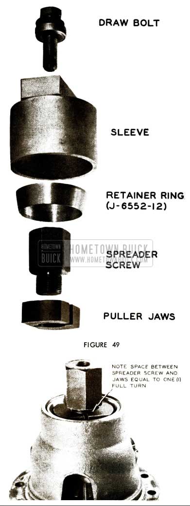
A new detail, J-6552-12, a double tapered retainer ring, has been added to the differential case side bearing outer race remover tool J -6552. See Fig. 49.
1956 Buick Torque Tube Flange Bolt
Using this ring with puller J -6552, as outlined below, will facilitate removal of bearing outer races with a minimum amount of effort from carrier with baffles as well as those without baffles.
- Insert jaws with lips down under the edge of the outer race. In some cases it may be necessary to force tool into position.
- Carefully thread spreader screw into jaws, making sure that threads are not crossed, leaving spreader screw one full tum away from jaws. See Fig. 50.
- Place retainer ring over jaws, tapping it down while pulling up spreader screw so that ring fits snugly around jaws, and then turn spreader screw tightly against jaws. See Fig. 51.
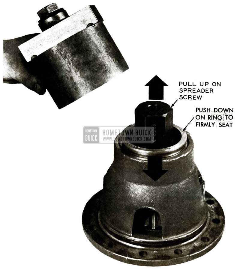
1956 Buick Differential Bearing Remover
- Place sleeve over assembled tool, resting base on flange of carrier.
- Insert draw bolt through washer, thrust bearing and sleeve and thread it into spreader screw of tool and pull.
NOTE: On first type carriers – without baffle, it will be necessary to raise spreader screw and jaw assembly with fingers to engage puller screw.
Retainer ring J-6552-12 will be shipped free of charge to each dealer who has received the tool, and it will be included as part of the tool m all future shipments.
INSTALLATION OF STRUT RODS
1956
To prevent the possibility of distortion or misalignment when servicing a rear axle assembly on a 1956 car, our Engineering Department recommends that during reassembly of rear axle, it is important to loosen the rear strut rod bolts before installing and tightening the front strut rod bolt.
The enlongated holes in rear of strut rods will permit fore and aft movement and insure proper alignment of axle housing to torque tube. After tightening front bolt (85 to 100 ft. lbs.), tighten rear bolts 90 to 100ft. lbs.
REAR AXLE BEARING REMOVER
Some time ago, it was determined that J -6191, Rear Axle Bearing Remover, was subject to undue breakage and dealers were asked to return all unbroken tools of this number so that they could be heat treated and remachined. Most dealers returned the tool promptly while others continued to use it until it was broken beyond use. In either case, Kent-Moore replaced the tool on a no-charge basis having stamped the reworked tool as 1-6191-A.
Because of the delay on the part of some dealers in returning the tools promptly, the normal stock carried by Kent-Moore was depleted and, as a result, it became necessary to issue instructions from this office on how to make a temporary tool. Such instructions were contained in a Special Dealer Service Letter dated July 20, 1956.
Subsequently, a few dealers also reported that the new tool (J -6191-A) was unsatisfactory and subject to breakage. On the basis of this information, tests were begun which disclose the following facts:
- It has been determined by our own laboratory tests that the J -6191-A has more than enough strength to pull the bearing if used properly. Many dealer contacts have also verified this fact.
- The tool cannot be made any stronger without cutting from solid stock instead of casting, thereby increasing the tool cost by a substantial amount.
- The retainer ring must be removed as it damages the bearing and places an abnormally high load on the tool.
- Actual tools submitted by dealerships have been checked and require 45,000 lbs. to break them. This is approximately 5 times the force required LO remove the bearing and two times as much pressure as can be developed by portable power equipment.
- Tools will break if there is excessive misalignment of the portable power equipment or the large floor mounted arbor presses. This misalignment causes uneven pressure thereby causing the tool to fracture and fail.
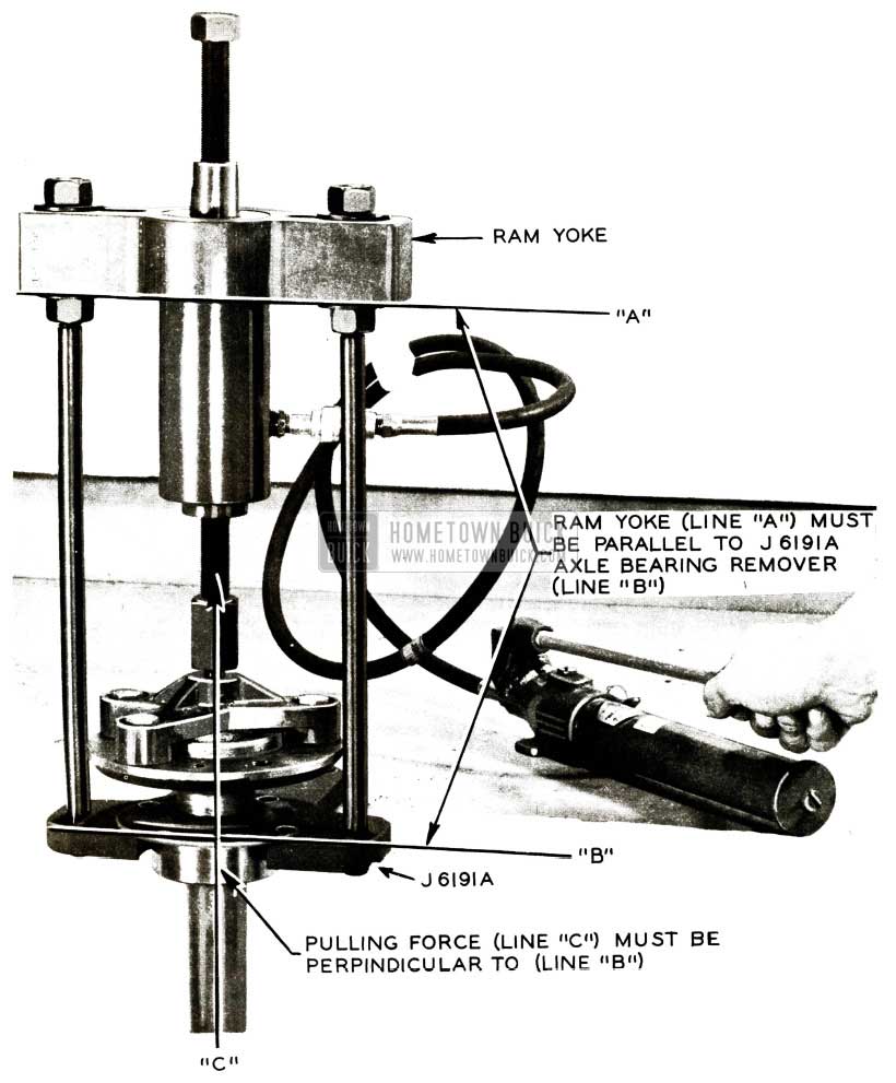
- Where the retainer ring is removed and reasonable care is taken to see that the portable ram (Fig.52) is properly aligned or that the floor mounted arbor press is properly shimmed where excessive misalignment exists, the tools will not break.
1956 Buick Torque Ball Retainer Interference
In view of these facts, the following procedure for the use of the J -6191-A, rear axle bearing tool, must be followed:
- The retaining ring must first be removed. While this is a help to the tool it is of far more importance that it be removed to prevent damage to the bearing.
- The axle assembly and tool must be assembled so that there is a straight pull or press on the shaft. See Fig. 52 for proper alignment of portable power equipment.
- After proper alignment is assured, apply force and remove the bearing. The J-6191-Atools will only break through improper use of misalignment and it is the responsibility of the person using the tool to see that these conditions do not exist. J -6191-A tools broken after this date will not be replaced free of charge by Kent-Moore.
In those cases where a dealer now has a J-6191-A tool, which broke before receipt of this bulletin, it may be returned to Kent-Moore for replacement. Kent-Moore will replace free of charge those tools received before September 30, 1956. Please note that replacement tools will not be available for approximately 60 days.
TORQUE BALL RETAINER INTERFERENCE
We have been informed by our Engineering Department that there are some early 1956 jobs equipped with torque ball outer retainers which are oversize or off center on the flange O.D. (outside diameter). Because of this condition, the outer retainer cannot be fully seated in recess in end of rear bearing retainer and will not allow proper centering of torque ball at assembly.
If clearance does not exist at any point between flange O.D. of outer retainer and shoulder on rear bearing retainer, it is likely that the off center condition exists, producing universal joint roughness on the coast down. When this condition is encountered, it can be corrected by filing down the outer retainer O.D. about .020” to provide sufficient clearance so that the retainer is free to float when the torque ball is assembled.
Alignment is helped at assembly by first lightly tightening 3 and 9 o’clock bolts part way, then alternately tightening remaining opposite bolts all around circumference of torque ball flange.
Repeat this tightening procedure at least two more times, increasing the torque each time. This will prevent distortion of retainers.
OIL LEAK AT REAR WHEEL BEARING
Following is a reprint of Special Red Band Service Letter, Dealer No. 169 dated January 18, 1956.
A few reports have been received on differential oil leaks at the rear wheel. These leaks show up first at the drain hole shield on the inboard side of the brake backing plate.
The majority of these leaks were caused by damage during assembly to wheel bearing seals. However, some leaks may be caused by insufficient crush of the wheel bearing against the wheel bearing inner gasket. This adjustment may be checked as described in BPS 2 .396 without pulling the wheel bearing; therefore, it is recommended that this adjustment be checked first in all leak complaints before replacing the wheel bearing seal.
Source of the leak may be determined by careful examination of the parts at removal to see if oil is present around the O.D. of the bearing. If oil is not present at bearing O.D., it may be assumed that the seal is leaking.
Whenever it is found necessary to remove the bearing to replace a defective seal, use Axle Bearing Remover Plate J -6191 in accordance with procedure given in the 1956 Product School Manual. CAUTION: Never attempt to remove bearings and bearing retainer together as damage to the bearings will result. It has been found that the Bearing Remover Plate J -6191, shown in Figure 53, is subject to breakage.
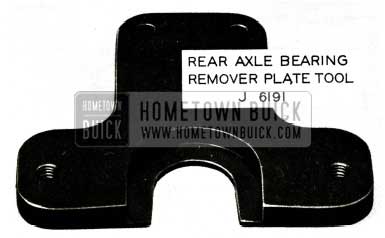
1956 Buick Rear Axle Bearing Remover Plate Tool
In the event that the tool does break, even though the retaining ring was first removed, the broken tool should be returned to Kent-Moore Organization, Inc., 1501 S. Jackson Street, Jackson, Michigan, for credit and replacement.
The J -6191 remover will be replaced with a J -6191-A which will be the J -6191 reheat-treated and remachined.
In order to provide every dealer with a satisfactory tool as soon as possible, it is requested that all J- 6191 tools (broken or unbroken) be returned immediately to Kent-Moore. Upon receipt of the J – 6191 tool, Kent-Moore will immediately return a J-6191-A on a no-charge basis. It is imperative that the unbroken tools be returned to Kent-Moore to pr9vide an inventory of tools for rework, thereby eliminating a long delay awaiting new castings.
FLOATING TYPE PROPELLER SHAFT
Some time ago the Engineering Department developed a floating-type propeller shaft which has proven very successful in eliminating customer complaints on rear axle noise in 1953 through 1955 models, or at least it reduces the noise to a point where it is acceptable to an owner.
These floating shafts are dimensionally the same as those used on past models, but are attached to the pinion with a coupling which has a slip fit on the spline and no pin. This new type shaft replaces the previous shaft used and may be ordered through all parts warehouses. Part and Group numbers and model application for the floating type propeller shaft are as follows:
1953 models 52 and 72; 1954-55 series 50 and 70 use Gr. 5.441 Part #1173840.
All other 1953-54-55 models use Gr. 5.441 Part #1173841.
The following are installation instructions for the floating type propeller shaft:
- Check new propeller shaft for straightness as outlined in paragraph 6-9 sub. par. (b) of the 1956 Shop Manual. NOTE: A new gear set and bearing should be used with the floating-type propeller shaft.
- Pack the cavity at the end of the pinion spline with a good grade of wheel bearing lubricant.
- Slide propeller shaft over pinion spline but do not install coupling pin.
- Install new propeller shaft in 3rd member housing, and complete installation of ring gear and case assembly, following procedure outlined in the 1955 Shop Manual, paragraphs 6-11 and 6-12.
NEW REAR WHEEL BEARING SEAL
We have been advised by Engineering that a new „O“ ring seal is being installed on 1956 after job rear wheel bearings. This new „O“ ring seal Gr.5.855 Part 1466050 is installed in the groove on the outer diameter of the rear wheel bearing, thereby providing an extra seal between the rear axle housing and the outer race of the bearing.
Whenever a rear wheel bearing is removed from the axle housing, it is suggested that the „O“ ring seal Gr. 5.855 Part 1466050 be replaced or if the wheel bearing is not equipped with this seal, we suggest that it be added during reassembly.
REAR AXLE BEARING REMOVAL
Following is a reprint of Special Service Letter Dealer No. 182 dated July 20, 1956.
Reports have been received indicating that some of the J -6191-A, axle bearing removers, are breaking. Our investigation discloses that tools have been broken due to the retainer ring not being removed prior to removing the bearing. The supply of these tools at Kent-Moore has been exhausted and it will be quite some time before more will be available. In order that the present rear axle correction program may continue in those dealerships where the tool has broken, it is recommended that the following procedure be used:
A satisfactory tool may be made locally out of cold roll bar stock in accordance with the dimensions shown in Figure 54.
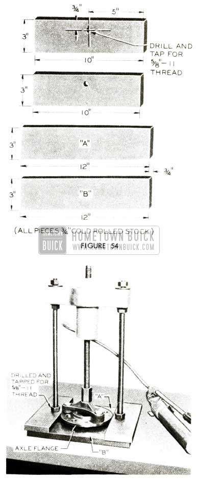
1956 Buick Rear Axle Bearing Removal
The dimensions shown are all approximate and may be varied to meet available material requirements. The tool is assembled as shown in Figure 55 with Bars A and B inserted between the axle flange and the bearing retainer plate. When this procedure is used, the retainer plate, Group No. 5.422, Part #1168826, will be damaged and in order to eliminate the possibility of oil leaks, it should be replaced.
When using the tool, first remove the retainer ring and then insert Bars A and B between the axle flange and the retainer plate as far as possible. The bearing retainer ring must be removed before the bearing is forced from the shaft as damage will result to the bearing if the retainer ring and bearing are pulled off as a unit. The retainer ring will slip off if its outside diameter is first heavily scored in
3 or 4 places with a chisel or blunt punch. After the ring has been removed from the shaft and the tool properly assembled, a reasonable amount of hydraulic pressure should be applied. If the bearing does not break free, it is advisable to strike the end of the shaft on the spline end with a few solid hammer blows. CAUTION: It is always advisable to wear eye protection when applying force with a hammer. The hammer blows along with the applied hydraulic force will normally break the bearing free and allow it to be removed. In addition to this method, most jobbers are also equipped to remove wheel bearings.
In view of this new procedure, the Parts Department has placed orders for additional retainer plates. It is anticipated that the additional plates will be available at all warehouses by the week of July 30, 1956.
As a result of the above procedure it will no longer be necessary toreturnanybrokenj-6191 orj-6191-A removers to Kent-Moore. A new procedure for handling the broken tools will be announced at a later date.
TORQUING REAR AXLE PINION NUT
1956 Model
In the 1956 Product School Manual, instructions are given to torque the rear axle pinion nut using torque wrench, J-1313-B on the outer end of the special handle, J-6246 (see paragraph 6-11, sub. par. a, Step 4 on Page 48 of the 1955 Product School Manual).
The following information applies to torquing the pinion nut with a torque wrench other than the J-1313-Bwhich is 18 inches in length.
The handle, J-6246, acts as a lever; therefore, the 80 ft. lb. ”Torque Wrench Dial Reading” applies only when using the J-1313-B wrench. If a different torque wrench is used, it will be necessary to refigure the required ”Torque Wrench Dial Reading by using the following formula. Torque Wrench Dial Reading= 250 ft. lbs. x length of Torque Wrench -;- by Length of Torque Wrench + 36 inches.
“Torque Wrench Dial Reading” is the foot pound torque required on the torque wrench to give the specified 250 ft. lb. torque required on the pinion nut.
”Length of torque wrench” is the distance in inches from the center of the square drive of the torque wrench to be used to the pivot point of the handle. If the handle is not pinned so that it pivots, measure to the center of the handle.
36 inches is the length of the handle, J -6246.
Leave A Comment
You must be logged in to post a comment.