CARBURETOR SPECIFICATIONS CHANGES
1956
Following are the latest carburetor specifications for 1956. Rather than list the individual changes, we are reprinting the specifications for the Carter, Stromberg and Rochester Carburetors; therefore, the information on carburetor specifications listed in BPS 2.396 should be disregarded.
NOTE: Only those items identified by an asterisk are affected by the Specification change.
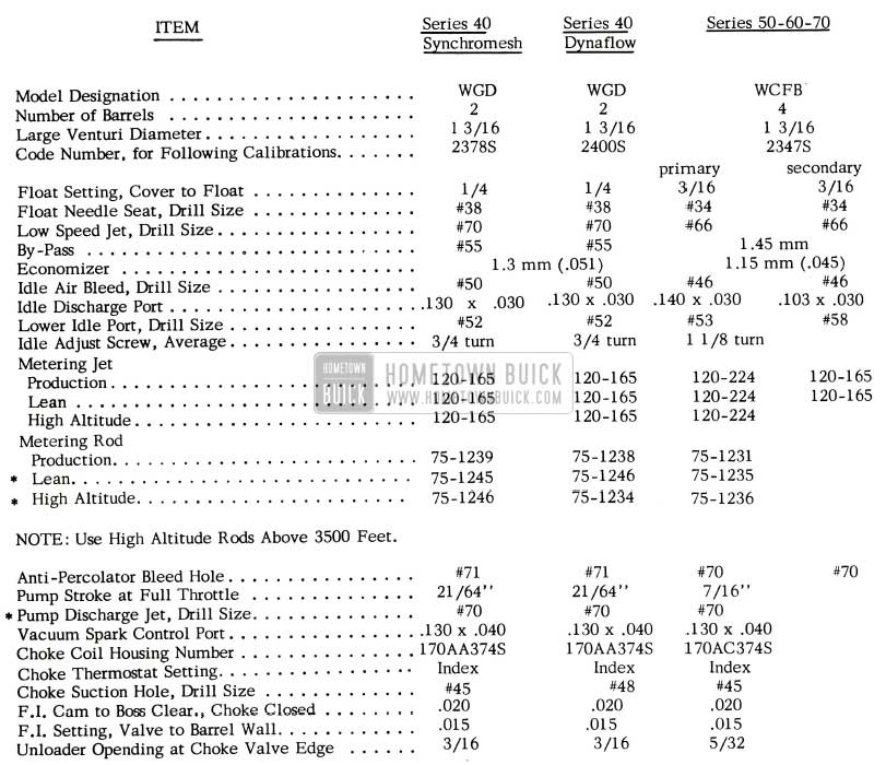
CARTER CARBURETOR & CHOKE CALIBRATIONS
IMPORTANT: Calibrations are governed by the CODE number on the attached code tag.
1956 Buick Carburetor Specifications Changes
NOTE: Use High Altitude Rods Above 3500 Feet.
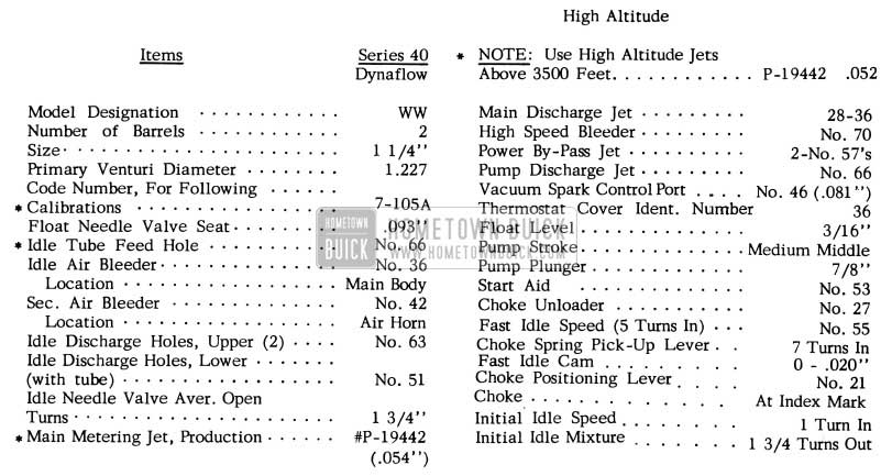
STROMBERG CARBURETOR AND CHOKE CALIBRATIONS
IMPORTANT: Calibrations are governed by the CODE number stamped on air horn.
1956 Buick Stromberg Carburetor and Choke Calibrations
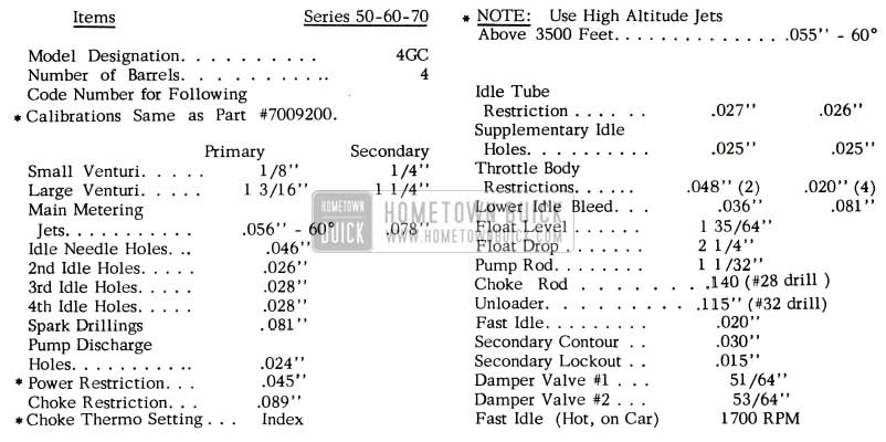
ROCHESTER CARBURETOR CALIBRATIONS
IMPORTANT: Calibrations are governed by the CODE number stamped on air horn.
1956 Buick Rochester Carburetor Calibrations
VACUUM SWITCH PISTON
It has been brought to our attention that in a few cases a vacuum leak at the vacuum switch has caused a rough engine idle. These vacuum leaks have been traced to the improper piston being used. See Fig. 14.
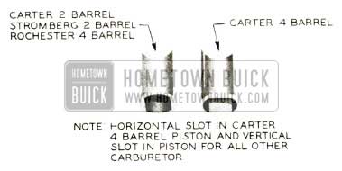
1956 Buick Vacuum Switch Piston
When the wrong piston is used the steel ball becomes trapped between the throttle valve shaft and the ramp side of the piston. When this occurs, it allows the vacuum passage to be open to atmospheric pressure, since the ball cannot raise to its seat.
BENT EXHAUST MANIFOLD THERMOSTAT STOP
Engineering advises that they have found that in many cases poor engine warm up characteristics were traced to the manifold thermostat stop Gr. 3.640
Part #1343658 being bent during assembly. In order to check this stop, it is suggested that it be checked with a known good one (from stock). Poor engine warm up is generally caused by the open end of the stop being pinched closer together. If this condition exists, it should be replaced. CAUTION: When reinstalling or replacing the stop make certain that the stop fits snugly on the shaft so that it will not rattle.
FUEL PUMP PRESSURE
Reports have been received from the field that some fuel pumps are producing excessive fuel line pressure. The fuel pump outlet pressure has been increased in 1956 to help reduce vapor lock during extreme hot weather operation.
Fuel pump pressure should be checked by placing an accurate pressure gauge in the fuel pump to carburetor line just in front of the fuel filter. Operate the engine at the idle speed of 450 R .P.M. The fuel pressure under these conditions should be 4 to 6 1/2 pounds per square inch. If pressure is not within these limits, the fuel pump should be removed and replaced by a new one.
EXHAUST MANIFOLD STUD CHANGE
1956
In order to strengthen the exhaust manifold to exhaust pipe joint or. 1956 cars, the size of the exhaust manifold stud has been increased from 3/8 diameter to 7/16 diameter. New part numbers have been released for the exhaust manifolds with the new 7/16 stud and also for the exhaust pipes, which had the hole size in the flange increased. These new part numbers are shown in the Parts Book as after- jobs and the original parts show 1st-jobs. Change points will not be issued on these parts as the stud size can be used for identification purposes. When stock is exhausted on the first type manifolds and exhaust pipes, the new parts will be furnished for all service replacements.
When installing an exhaust manifold with a 7/16 diameter stud on a first job car, it will be necessary to enlarge the holes in the exhaust pipe flange to accommodate these new larger studs. When installing the new exhaust pipe on a first jobs exhaust manifold with the old 3/8 diameter stud, it will be necessary to use two of group 0.027 Part 1234605, flat washer or an equivalent standard 3/8 flat washer to prevent the nut from pulling through the larger hole when the joint is tightened.
Following are the part numbers of the new manifolds and pipes which will replace the old parts when present stocks are exhausted:
- 3.601-1169265 Man. to be replaced by 1175577
- 3.601-1169001 Man. to be replaced by 1175581
- 3.601-1168110 Man. to be replaced by 1175576
- 3.609-1168285 Exh. Pipe to be replaced by 1175584
- 3.609-1168730 Exh. Pipe to be replaced by 1175580
- 3.609-1168731 Exh. Pipe to be replaced by 1175587
In order to avoid reoccurrence of the 3/8 diameter stud breakage on early 1956 manifolds, it is recommended that the 7/16 diameter stud Gr. 3.602 Part #1175533 and nut Gr. 3.602 Part #1175534 be used as replacement for 3/8 diameter stud and nut combination. In order to do this it will be necessary to drill out the old stud and enlarge the hole to 0.3680 or drill size “U”. Then using a 7/16-14 tap, thread this hole to accommodate the new larger stud. With the use of this new stud, it will be necessary to file larger holes in the flange on the front exhaust pipe.
STROMBERG CARBURETOR KIT
NOT A CAMPAIGN
Following is a reprint of Special Red Band Service Letter, Dealer No. 164 dated November 25, 1955, relative to Stromberg Carburetor Modification Kit.
We have been informed by our Engineering Department that a few of the early two-barrel Stromberg carburetors 1172341 (identified by Code No. 7-105) used on 1956 Series 40 jobs, are operating slightly lean in the low and high speed circuits, regardless whether the engine is hot or cold. The only indication of this lean condition is on moderate acceleration, and it cannot be detected during heavy acceleration.
Engineering has developed a repair kit that will eliminate this condition. The kit consists of idle tubes, main metering jets and main discharge jets and it will be available for distribution under Group 3.725 and Part No. 1392722. Note: (Group number shown in Red Band Letter is in error). We would like to emphasize that all carburetors bearing Code No. 7-105 will not necessarily require this modification. Therefore, this is not to be misunderstood as a campaign, and only when an owner complains of the above mentioned symptoms is this kit to be used. All carburetors identified by Code No. 7-105A will have these new changes in them.
The instructions for making the installation of the kit are as follows:
- Remove the carburetor.
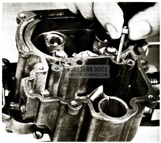
- Remove the air horn assembly from the carburetor.
- Remove both idle tubes, as shown in Figure 15, and replace with the two (2) idle tubes furnished in kit.
1956 Buick Carburetor Manifold Stud Breakage
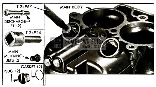
1956 Buick Carburetor Main Body
The flat rate time for this modification is .9 hr.
FUEL PUMP REPLACEMENT
An examination of fuel pumps replaced in the field for various reasons and returned to the factory indicates that a large percentage of the total are being needlessly replaced. For example, many fuel pumps tagged as having been replaced because of excessive oil consumption are ok in every respect and did not contribute to oil consumption. Furthermore it has been found in numerous tests here at the factory that fuel pumps will not cause oil consumption. If there is an excessive oil consumption condition, it is due to some condition other than a fuel pump. In other cases many of the tags attached to the fuel pumps do not state why they were replaced.
In the future, any pumps replaced because of excessive oil consumption will be returned to the dealer and credit rejected. Also, if the tag does not state why the pump was replaced, the part will be returned to the dealer and credit rejected by the zone office.
MANIFOLD STUD BREAKAGE
Reports have been received regarding exhaust manifold stud breakage. In order to avoid a reoccurrence of this breakage, it is recommended that when installing a new stud that a 7/16 stud, Gr. 3.602 Part 11 75533 be installed in place of the old 3/8 stud. In order to do this it will be necessary to drill out the old stud and enlarge the hole to 0.3680 or drill size “U”. Then using a 7/16-14 tap, thread this hole to accommodate the new larger stud. With the use of this new stud, it will be necessary to file larger holes in the flange on the front exhaust pipe.
NEW GASOLINE FILTER
Because of rust problems encountered with our present Moraine fuel filter, a new two-piece gasoline filter with a replaceable porous element will go into production soon. The replacement element kit will be available under Gr. 3.203 Part #5452162 as shown in Figure 17. The gasoline filter assembly will be available under Gr. 3.203 Part #5452170.
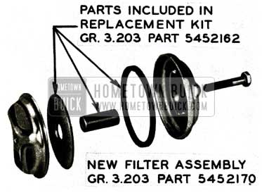
1956 Buick Gasoline Filter
ACCELERATOR PEDAL RUBBER STOPS
1956
It has been brought to our attention that some 40-60 series cars may have the wrong accelerator pedal rubber stops installed on them.
If a 50-70 accelerator pedal rubber stop is installed on a 40-60 series car, full throttle opening cannot be obtained due to the difference in size of the rubber stops shown in Figure 18.
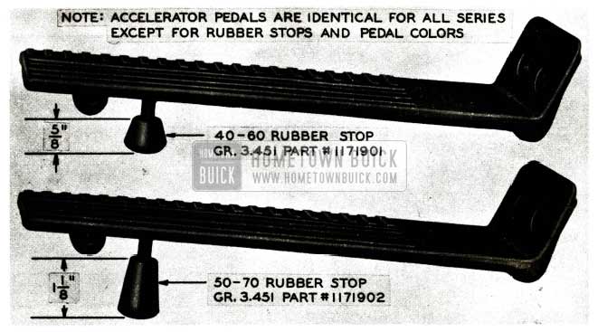
1956 Buick Gas Pedals
Therefore, when conditions of this type are encountered, make sure the correct stop is used for each series. The 40-60 series cars use a 5/8″ rubber stop, Group 3.451 Part #1171901 and the 50-70 series use a 1 1/8″ stop, Group 3.451. Part #1171902
It is also suggested to check the throttle linkage to make sure no binding condition exists and that the proper 1/16 ” clearance is obtained between the lower lever and stop lug.
FUEL PUMP ARM FAILURE
1956
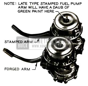
Due to a change in design of the fuel pump arm from a forging to a sheet metal stamping on 1956 cars, some trouble has been experienced with the sheet metal stamped arm hitting the timing chain cover. The arm hits the cover at the parting line at the top of the fuel pump opening about 1 1/2″ from the mounting pad face and produces a light, sharp knock. NOTE: (This knock should not be confused with any other type fuel pump noise.) Evidence of interference of the fuel pump arm to the timing chain cover can be found on the pump arm.
The difference between the forged fuel pump arm and the metal stamped arm can be seen in Figure 19.
1956 Buick Fuel Pump Arm
Whenever conditions of this type are encountered in the Field, the fuel pump should be replaced with one having a forged arm or the late type sheet metal stamped arm which can be identified by a daub of green paint on the top of the fuel pump cover. When submitting an AF A for a damaged fuel pump arm, it should be stated on the AFA just what type arm the fuel pump had, Forged or Stamped Metal.
ACCELERATING PUMP PLUNGER SETTING
1956 Rochester Carburetor
From product reports received to date it is apparent that some confusion surrounding the Rochester accelerator pump plunger setting exists in that some dealers are setting the pump stroke at 1 1/32″ and some at 1 3/32″.
This is to advise that the factory recommended setting is 1 1/32″. In hot climates, however, where a flat spot on acceleration is encountered when engine is hot, the pump plunger setting may be reduced to 1”. This setting may not re move the hesitation 100 % but in most cases is sufficient to eliminate the complaint.
Flat spot complaints under the conditions described above are further aggravated if pump plunger setting is at 1 3/32 “, which is too rich under very hot conditions. However, the 1” pump stroke in colder climates where temperatures drop below approximately 20°F. may produce a lean condition causing a flat spot during heavy acceleration. Therefore, some discretion should be used be for adjusting the pump plunger stroke to the 1” setting. See page 3-62 in the 1956 Buick Shop Manual for the pump rod measuring and adjusting procedure.
CHOKE PISTON CHANGE
Following is a re print of Special Red Band Service Letter, Dealer No. 166B.
The information furnished in this letter will supersede that given in Special Service Letter – Dealer No. 166A. In order to obtain a more effective method of eliminating stalling and loading- up condition on Rochester Carburetors during the first few miles of operation in cold weather, the following kit is being made available for service.
Choke Modification Kit Gr. 3. 750 Part #7009948 – This kit includes:
- Choke housing
- Thermostat cover, coil and gasket
- Choke housing gasket
- Choke piston
- Choke lever and link
- Choke piston pin.
Arrangements have been made with the Parts Department to automatically substitute the above mentioned kit for every order received for choke piston Gr. 3.752 Part #7009777 which was cancelled as d escribed in Special Service Letter – Dealer No. 166A. It will, therefore, not be necessary to reorder if choke piston orders have already been placed.
Parts contained in choke modification kit may be installed by removing air cleaner and choke housing assembly from carburetor and re placing choke parts with those included in modification kit. After installation of kit, set choke cover at index. NOTE: Make sure that the choke unloader operates properly when the accelerator pedal is depressed. A clearance of .140″ should exist between choke valve and air horn dividing wall when idle adjusting screw is resting on second step of fast idle cam. (Bend choke rod to obtain specified clearance). The fast hot idle adjustment should be set at 1700 RPM with fast idle screw resting on high step of the fast idle cam.
After performing the above procedure stamp the letter “C” on the lower left corner of the brass identification tag so that the carburetor can be identified as one having the new choke housing assembly. All production carburetors having this choke modification will be identified by letter “C” stamped on identification tag.
Flat rate time to install the choke modification kit is .4 hr. This modification kit is to be installed only in cases where an owner complains and is not to be campaigned.
WATER IN CHOKE HOUSING
1956
We have received a few reports stating that water and ice have been found in the choke thermostat housing on some 1956 cars. Dealers reported that after replacing the exhaust manifold, the trouble was eliminated.
In checking some of these manifolds which were returned to the factory, it was found that the heat tube which is pressed into the manifold was not located properly at the lower inner end, thereby allowing exhaust gases to pass into the automatic choke housing, which explains the reason for ice found in some choke housings. Whenever a condition of this type is encountered, the exhaust manifold must be replaced.
FUEL LINE TORQUE SPEC.
We have received a few reports that the flexible gas line fittings were stripped, causing a leak. The failure occurs at the fitting where the line attaches to the steel gas line which was caused by over torquing the fitting. Some checks were made which showed this fitting would fail at a torque of from 15 to 25 ft. lbs. while 7 to 10ft. lbs. torque is sufficient to insure no leaks.
It is recommended that when servicing this fitting to tighten this connection by hand, using two short open end wrenches, holding the brass fitting on the end of the flexible line with one wrench, while tightening the steel fitting with the other.
CARBURETOR PUMP SPRING CHANGE
Rochester Carburetor 1956
In an effort to reduce stumbling condition which sometimes occurs on light acceleration under cold operation, our Engineering Department advises that by changing the accelerating pump spring on Rochester carburetor from a .041″ to .042″ (wire dia.) spring, some improvement could be gained.
In view of this, all production Rochester carburetors built since March 2, 1956 will have the .042″ (wire dia.) pump spring installed. These carburetors can be identified with a suffix date stamp after the part number, such as C6, D6, etc.
It is, therefore, suggested when a complaint of stumbling on Rochester carburetor is encountered on a 1956 carburetor built prior to March 2, 1956, the .042″ (wire dia.) spring Gr. 3.838 Part #7009651 should be installed. Obviously, the installation of the heavier spring will not necessarily correct all stumbling complaints, as the source of difficulty may be elsewhere.
The flat rate time to install the .042″ (wire dia.) pump spring in a Rochester carburetor is .7 hr. with carburetor assembly left in car. This flat rate time includes R&R air cleaner, D&C gas line, air horn and pump plunger assembly.
IMPROVED FUEL ECONOMY
1956
To affect an increase in fuel economy up to approximately one mile per gallon on 1956 cars, production carburetors are now being equipped with leaner metering rods and jets and may be identified as follows:
- Carter four-barrel carburetors are now being built with metering rods #75-1235 Buick Gr. 3.806 Part #1173521 and can be identified by the letter G, H, J, etc. following the Code #2347S.
- Carter two-barrel carburetors are now being built with metering rods #75-1246 Buick Gr. 3.806 Part #11 73405 and can be identified by the letter G, H, J, etc. following the Code #2400S.
- Stromberg two-barrel carburetors – Gr. 3. 725 Part #1172341 are now being built with main metering jets P-19442 size .053 Buick Gr. 3. 792 Part #1173054 and can be identified by the Code #7 -1058.
- Rochester four-barrel carburetors – Gr. 3.725 Part #7009900 are now being built with primary main metering jets size .055 Gr. 3. 792 Part #7001860 and can be identified by the code tag having a letter “D” stamped on the tag.
The flat rate time to install the above jets and metering rods is as follows:
Carter two and four-barrel – Flat rate time – .3 hr. Includes: R&R air cleaner and metering rod cover and replace metering rods and adjust metering rods.
Stromberg – Flat rate time – .8 hr.
Includes: R&R air cleaner and carburetor and replace jets, readjust carburetor idle if necessary. Special tool, T -24924, is used to R&R jets.
Rochester – Flat rate time – .6 hr.
Includes: R&R air cleaner, D&C gas line, accelerator pump linkage, automatic choke linkage, unloader linkage and R&R carburetor air horn and replace jets.
Leave A Comment
You must be logged in to post a comment.