AIR CONDITIONER OUTLET “CAMPAIGN”
The following is a reprint of Special Service Letter – Red Band #180 dated May 18, 1956 WHICH HAS BEEN CORRECTED.
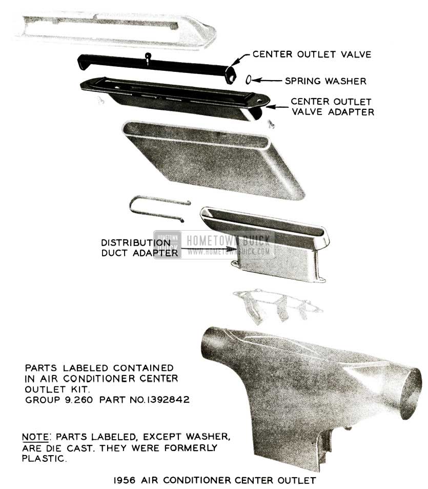
Complaints of insufficient volume of air flowing from center instrument panel air outlet valve have been traced to warped or collapsed plastic center outlet valve (shutter), plastic center outlet valve adapter, and/or plastic heater distribution duct adapter. See Figure 95.
1956 Buick Air Conditioner Center Outlet
NOTE: Figure 95 shows only one spring clip at the lower end of the connector tube (rubber boot). Correct assembly calls for two, one on each side of rubber boot. It is also necessary that the clips maintain a tight fit across the entire bottom end of this boot to avoid possible air leaks in this area. Therefore, when making this installation be certain both clips are used.
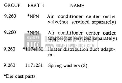
1956 Buick Air Conditioner Outlet Parts
To eliminate this condition, Production has used since approximately May 9th die cast parts in place of plastic ones mentioned above. Also, due to the possibility of these plastic parts becoming deformed d e to extreme heat (when car is parked in sun, windows closed, with ambient temperature approximately 100 degrees), it has been decided to campaign all air conditioner equipped cars built through approximately May 9, 1956. The Parts Department is, therefore, making available an Air Conditioner Center Outlet Kit Gr. 9.260 Part # 1392842, which includes the following parts identified in Figure 95.
NOTE: The air conditioner center outlet valve will be primed ready to be painted to match the car trim; other parts need not be painted.
Air conditioner equipped cars having serial numbers lower than those listed below are to be campaigned.
ASSEMBLY PLANT – SERIAL NUMBER
Flint – C1143959
South Gate – C2047064
Linden – C3047424
Kansas City – C4042491
Wilmington – C5036842
Atlanta – C6037999
*Framingham
Arlington – C8029276
*Air conditioner units not installed at this plant.
NOTE: After installation of reworked instrument panel center outlet assembly, coat inside one end of connector tube (rubber boot) with 3M black weatherstrip cement to a depth of one (1) inch. Then work cemented end of rubber boot up around center outlet adapter approximately one (1) inch. It will not be necessary to use cement at lower end of rubber boot at distribution duct adapter because spring clips are used to secure boot at this location.
Air conditioned cars equipped with die cast valve and adapters may be identified by observing the appearance of the distribution duct adapter from underneath instrument panel. Die cast adapter will have bright shiny white metal appearance; plastic adapter will be yellowish in color.
NOTE: Some air conditioner equipped cars to be campaigned already have die cast center instrument outlet valve (shutter) installed; therefore, do not attempt to identify car by this valve. In such instances, it will only be necessary to replace the two plastic adapters.
Flat rate time for installation of Air Conditioner Center Outlet Kit Gr. 9.260 Part 1392842 is 1.2 hrs., which includes: D & C air conditioner heater defroster control panel, bowden wire from defroster and heater distribution duct valve, and defroster hose from left defroster outlet at windshield; R & R radio, defroster and heater distribution duct assembly, distribution duct adapter, air conditioning center outlet assembly from instrument panel, adapter from center outlet, valve (shutter) from instrument panel center outlet and shim as required, and refinish valve (shutter).
Submit one (1) AFA per car with parts which were replaced to Zone M.R. Room.
AIR CONDITIONER
FIELD INSTALLATION PACKAGES
Air conditioner field installation packages Gr. 9.169 Part #981756, which include the new die cast valve and adapters will be identified by a label marked “Includes die cast valve and adapters”. Any packages received without this label will have to be reworked by ordering Kit Gr. 9.260 Part #1392842.
Plastic parts removed from package #981756should be returned to Zone M. R. Room with AF A. II should be noted on separate AF A for each package reworked that plastic parts were substituted with die cast parts and Gr. 9.260 Part #1392842 should also be shown on AF A in space provided for part and group numbers. NOTE: No credit will be allowed for labor to rework air conditioner packages.
AIR CONDITIONER INFORMATION
1956
AIR CONDITIONER COMPRESSOR SEAL
We are advised by the Parts Department that the compressor oil drain hole seal (small flat “o” ring between coil and seal housing and compressor flange) is not included in the compressor shaft seal package Gr. 9 .175 Part #5876740. In the event of loss or damage to this seal, it may be ordered under Gr. 9.186 Part #5918627.
ENGINE OVERHEATING AIR CONDITIONED CARS
In the event that a complaint of coolant boiling and overflowing the radiator is encountered on an air conditioner equipped car, observe the following items and correct as required:
- Make certain radiator water is maintained at the proper level.
- Make certain cooling system contains no antifreeze.
- Make certain that a 13 lb. pressure cap is installed and is not leaking.
- Make certain compressor belts are tensioned properly.
- Make certain that a five (5) blade fan is installed.
- Make certain Air Conditioner is not overcharged and that it does not have air in the system.
- Make certain that the condenser and radiator are not obstructed by insects, leaves, etc.
- Make certain engine timing is not retarded past T.D.C.
- Make certain there is no internal obstruction in cooling system (collapsed hose, etc.).
- Make certain there is no undercoating on radiator lower tank or core.
Owners should be advised to use low range on slow hard pulls or in traffic under extreme heat conditions. Prolonged periods of idle, especially after a long fast run may also cause overheating as will overloading by draging brakes, etc.
CLEANING EVAPORATOR COIL
If it becomes necessary to clean the evaporator interior and cooling coil to remove accumulation of dust, foreign deposits, etc., it may be accomplished by performing the following:
- With engine and blower off, move upper Air Conditioner Control lever to “Off” position (extreme left) making certain that this completely closes the recirculated air valve.
- Remove filter seal and filter and wash filter with soap and water or other solvent and dry thoroughly.
- Remove blower motor and blower fan assembly by removing the fi\e (5) screws that hold the mounting plate to the insulated blower case. These screws are located under the foam insulating pad on the blower motor mounting plate.
- Remove the evaporator drain grommet and drain grommet cleaner (jiggle pin) from the evaporator case (toward right side on bottom surface).
- Back wash the evaporator core by gently flowing water over the core through the hole in the blower case. CAUTION: Do not use a high velocity nozzle which might damage the core air centers and use water in moderate quantities to prevent overflowing the recirculated air valve into the passenger compartment.
- Reinstall parts removed in Steps 2, 3 and 4, after first applying a light film of engine or compressor oil to the filter. This may best be done by saturating a piece of soft cloth with oil then wiping both sides of the filter screen with it.
FREON CHARGE
In checking the system for sufficient Freon charge, the engine should be operated at 1000-1200 RPM using a fan or blower to increase the air flow through the condenser. The hot gas by-pass control lever should be placed in the maximum cold position. Under these conditions the sight glass should show a solid column of Freon if the system is completely charged (5.5 lbs.).
COMPRESSOR REPLACEMENT
Whenever a compressor is replaced the removed compressor should be drained and the oil measured. Then the replacement compressor should be drained into a clean container and an amount of oil equal to that drained from original compressor replaced. The reason being that some of the original oil charge may be trapped in the system and if a compressor with a full charge of oil is installed, it is possible to have nearly a double charge of oil unless the above procedure is followed.
When a compressor is drained as explained above, the holding charge of Freon is lost, trapping air in the compressor. After the new compressor is installed, but before it is operated, it should be purged of air. This is done by slowly loosening the pressure relief valve at the top of the compressor until a slight hiss of escaping gas is noticed. This should bleed for one to two seconds, then tightened back down. The compressor should then be operated for a few minutes at about 1000-1200 RPM to build up head pressure, then the purge repeated. Caution should be taken not to loosen the pressure relief valve too far or fast, because if it pops_ out, the whole charge will be lost.
If an unknown quantity of oil is lost through accident or a Freon leak, Par. 11-8 e of the 1956 Shop Manual should apply.
AIR CONDITIONER SPEC.CHANGE
Engineering has recommended that the air conditioner clutch cover cap screws be tightened to 3 to 5 ft. lbs. (36 to 60 in. lbs.). The previous torque specification at this point was 5 to 7 ft. lbs. which, Engineering felt, might distort the clutch cover. Whenever any service work is performed that involves disassembly of the clutch, these clutch cover retaining screws should, therefore, be torqued only to 3 to 5 ft. lbs.
OBJECTIONABLE ODORS
1956 Air Conditioner
Scattered reports received on objectionable odors in air conditioned cars have been traced to the insulated air tubes used between the blower and the outer heater-defroster core housing. Two types of insulated hose have been used in production, one type has one {1) layer of 1/4″ thickness foam rubber insulation and the second type has two (2) layers of 1/8″ thickness foam rubber. In most cases the hose having two (2) 1/8″ layers of insulation was found to produce objectionable odors; however, a few 1/4″ insulated hoses have also produced objectionable odors. In either case, the only corrective measure is to replace the hose.
COMPRESSOR OIL CHECKING
Air Conditioner
Recent product reports indicate that compressor seal replacement, in many cases, is not effective at stopping leaks in this area. Engineering feels that some of the second failures may be due to an inadequate supply of oil in the compressor. NOTE: They also feel that the compressor shaft should be inspected for scoring before a new seal is installed. A rough or scored shaft will cause unsatisfactory seal performance; therefore, the compressor will have to be replaced. This condition may be eliminated by making very certain that each system that has been opened for any reason receives the following check for sufficient compressor oil.
Operate unit ten minutes and check for solid column of Freon 12 at sight glass; if necessary, add Freon until column is solid (no bubbles in sight glass) then 1/2 lb. more. Check oil level in compressor and add oil, 4 oz. at a time if necessary.
COMPRESSOR CLUTCH
SWITCH FAILURES
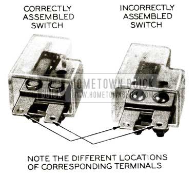
We have been advised by our Engineering Department that on some early air conditioners the compressor clutch switch was incorrectly assembled during manufacturing in that the switch terminals were inadvertently reversed causing the connection terminal to be improperly color coded. See Figure 96.
1956 Buick Compressor Clutch Switch Assembly
In the event that this has happened, the feed line (brown wire) will be connected directly to ground, causing the 5 ampere fuse to bum out with the air conditioner turned off. If this difficulty should occur, it is not necessary to replace the switch unless the switch is damaged by the contacts being burned. The correct operation of the switch may be obtained by reversing the wire so that they are opposite to the color markings on the case.
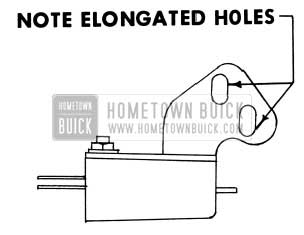
Another difficulty experienced with the early type switch was that the switch could not be positioned properly to affect compressor operation at all times when the control lever is pushed to the extreme right position.
Engineering advises that if adjustment of this switch is required it may be accomplished by elongating the mounting holes as shown in Figure 97 and shifting so that it will close switch contact and energize the compressor clutch when control lever (“Frigidaire”) is moved to the extreme right “On” position.
1956 Buick Compressor Clutch Switch Mounting Holes
NOTE: Later type production switch will have elongated holes to facilitate switch adjustment.
1956 AIR CONDITIONER SERVICING INFORMATION
Because of the numerous bulletins pertaining to servicing the Buick air conditioner and in order to put this information in a more condensed and usable form, we have compiled this information along with new information into one complete bulletin for your convenience.
- FUNCTIONAL TEST DATA.
- This data is to be used when checking a car with a 1956 air conditioner. Car conditions to functional test are:
- No sun load.
- Hood closed.
- Doors open.
- Heater Ranco valve off.
- Hot gas valve set for maximum cooling.
- Fan or blower in front of radiator to help cool condenser and radiator.
- This data is to be used when checking a car with a 1956 air conditioner. Car conditions to functional test are:
Each car that has had the unit repaired or recharged is to be tested in accordance with the following ”Functional Test Data”.
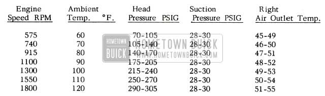
1956 Buick Air Conditioner Temperatures
NOTE: Set engine speed as designated for each corresponding ambient temperature.
NOTE: All Air Conditioning units are shipped charged with 5.5 lbs. of Freon 12. This is a full charge and precaution should be taken to charge no more than this quantity for a recharge after repairs. In the event it becomes necessary to set the “Hot Gas By-Pass Valve” to correct the suction pressure, the following procedure is to be used:
- Disconnect the valve control cable.
- Remove the valve control lever and counter balance spring.
- Remove the nylon cam follower. See Fig. 98.
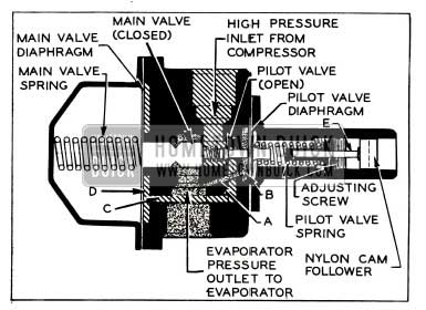
1956 Buick Air Conditioner Nylon Cam Follower
- Occasionally it will be difficult to obtain the specified pressures when the ambient temperatures are low (60° – 80°F). However, Engineering advises that some stabilization may be accomplished by providing forced circulation of air through the condenser and radiator by placing a large capacity fan or blower directly in front of the car, blowing directly into the grille. This forced circulation should approximate a 10 mph wind. Further tests have shown that conditions of high relative humidity have a very detrimental effect on the efficiency of the unit since no cooling benefit is derived from the cold water that drains out of the evaporator housing. This will cause some variation in suction pressures and outlet temperatures from those values given in the functional test.
EXPANSION VALVE
An improvement can be made in 1956 air conditioner performance by adjusting the expansion valve four and one-half turns (counterclockwise) from the fully closed position, rather than the previously recommended five turns. This will provide a 3° lower outlet air temperature. Production units have incorporated this change on jobs built after April 15, 1956.
HOT GAS BY-PASS VALVE
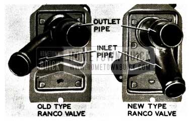
Early in 1956 a change was made to the Hot Gas By-Pass Valve and by-pass valve to evaporator hose to affect the interchangeability of air conditioner units between various 1956 models.
Approximately 1000 of the first type hot gas by-pass valves and hose arrangements shown in Fig. 99 were installed in Series 50-60-70 cars built prior to November 7, 1955.
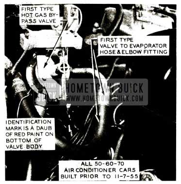
1956 Buick Air Conditioner Hot Gas by-pass Valve-First Type
All 40 series and 50-60-70 cars built after November 7, 1955 with air conditioners, have the second type parts arrangement shown in Fig. 100.
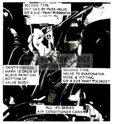
1956 Buick Air Conditioner Hot Gas by-pass Valve-Second Type
The first type parts can be identified by a daub of red paint on the bottom of the by -pass valve body and elbow fitting on end of evaporator hose. The second type is identified by a daub of black paint in the same location. See figs. 99 & 100.
If it becomes necessary to replace either the hot gas by-pass valve or the by-pass valve to evaporator hose on a car equipped with the first type parts, it will be necessary to replace both parts as replacement parts available through the Parts Department are for the Second type arrangement and are not interchangeable.
The group and part numbers of the second type are as follows:
Gr. 9.212 – Part 1998809 – Valve Hot Gas By-Pass
Gr. 9.225 – Part 3136227 – Hose By-Pass
COMPRESSOR
- Removal and Installation (revised from Shop Manual).
CAUTION: Observe precautions in handling Freon 12 outlined in Buick Air Conditioner Manuals. - Remove protective caps from gauge fittings of high and low pressure valves on rear end of compressor.
- Connect charging lines of Pressure Gauge Set (Fig. 101) to gauge fittings of both valves, with both valves of Manifold J 5415 closed.
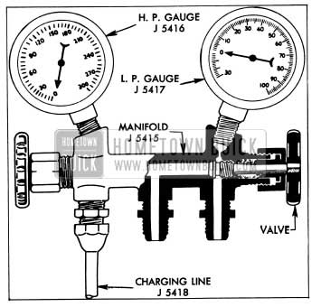
1956 Buick Air Conditioner Compressor Pressure Gauge Set
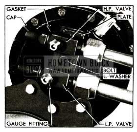
1956 Buick Air Conditioner Compressor Pressure Gauge Fitting
Caution should be taken not to loosen the pressure relief valve too far or fast, because if it pops out, the whole charge will be lost.
Compressor Field Service
It has been found that in most cases unusual noises emanating from the compressor have been caused by broken suction or discharge valve reeds. If only one valve reed is broken it may or may not make a noise; however, efficiency of the compressor will be reduced approximately 20%. Broken valve reeds may sometimes be detected by disconnecting compressor pulley belts and energizing compressor clutch. Then rotate pulley by hand, observing by feel compression impulses of each piston. If one valve reed is broken, only four compression impulses will be felt per one complete revolution of the pulley. If valve reed is not broken, five impulses will be felt for each revolution. This check will work satisfactorily if proper charge of refrigerant is in the system.
Under low temperature operating conditions (below 70° F) when the air conditioner is used for dehumidification, an inherent shaft end play noise may be heard. This is caused by the low head pressure existent under such conditions and should not be confused with the noise due to a broken valve reed. Under higher operating temperatures and pressures, this noise will disappear and no attempt to eliminate it should be made. Broken valve reed noise, however, will not diminish with either increased or decreased temperatures and pressures.
When this condition is encountered, the valve reeds may be removed and inspected by performing the following:
Disassembly Procedure
- Remove compressor from car as outlined in 1956 Shop Manual, par. 11-8, sub. par. a. Also drain compressor oil into clean measured container to determine how much oil is still trapped in the system. NOTE: Extreme care should be exercised when disassembling the compressor to keep internal parts free from dirt and moisture contamination. Do not keep it open any longer than necessary.
- Place compressor on clean bench in vertical position with weight resting on clutch pulley assembly.
- Tape heavy sheet of paper around compressor shell to form protective skirt to prevent oil from running down on clutch parts. See Fig. 103.
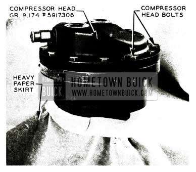
1956 Buick Air Conditioner Compressor Head
CAUTION: Some oil may be trapped in compressor head and if allowed to run into clutch will ruin clutch plates.
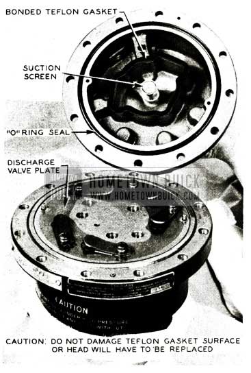
1956 Buick Air Conditioner Compressor Gasket
Be careful not to scratch or otherwise damage the teflon gasket as it seals the high pressure side of compressor from low pressure side. If gasket surface is damaged, the compressor head, Gr. 9.174 Part #5917306 will have to be replaced.
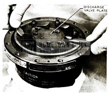
1956 Buick Air Conditioner Compressor Discharge Valve Plate
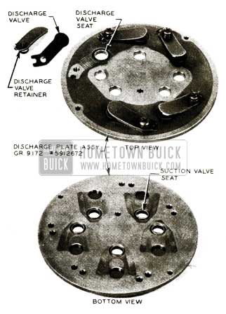
1956 Buick Air Conditioner Compressor Discharge Valve Assembly
NOTE: Any damage to the valve seats, discharge valves or retainers will necessitate replacement of discharge plate assembly, Gr. 9.172 Part #5912672.
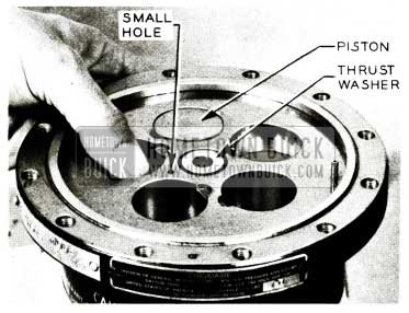
1956 Buick Compressor Piston
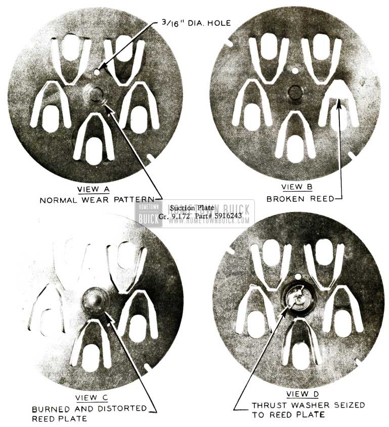
1956 Buick Compressor Suction Plate
It is a known fact that burned thrust washers result from operating the refrigeration system without having a full sight glass of liquid refrigerant. A shortage of Freon 12 does not permit normal oil return to compressor body, causing compressor to operate with insufficient lubrication.
Reassembly Procedure
- Before reassembling compressor, note that the bronze thrust washer extends slightly above the surface of the cylinder casting. This is normal due to the force of the spring in the shaft seal at the opposite end of the shaft. CAUTION: Do not alter or change the relative position of the thrust washer and shims.
- Place the suction reed plate (thin) over the two dowel pins in the cylinder so that the 3/16″ dia. hole shown in View A, Fig. 108 which ‘is approximately 3/4″ from the center of the plate, mates with the smaller hole in the cylinder block shown in Fig. 107. This hole is located between two of the piston bores.
- Install discharge plate (thick one) over the two dowel pins shown in Fig. 109.
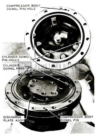
1956 Buick Compressor Cylinder Dowel Pin Holes
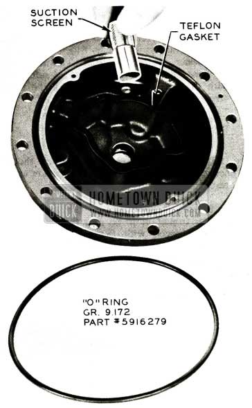
1956 Buick Compressor O-Ring
The Flat Rate time to perform the above operation with compressor removed is .5 hr.
EVAPORATOR COIL
If it becomes necessary to clean the evaporator interior and cooling coil to remove accumulation of dust, foreign deposits, etc., it may be accomplished by performing the following:
- With engine and blower off, move upper Air Conditioner Control lever to “Off” position (extreme left) making certain that this completely closes the recirculated air valve.
- Remove filter seal and filter and wash filter with soap and water or other solvent and dry thoroughly.
- Remove blower motor and blower fan assembly by removing the five (5) screws that hold the mounting plate to the insulated blower case. These screws are located under the foam insulating pad on the blower motor mounting plate.
- Remove the evaporator drain grommet and drain grommet cleaner (jiggle pin) from the evaporator case (toward right side on bottom surface).
- Back wash the evaporator core by gently flowing water over the core through the hole in the blower case. CAUTION: Do not use a high velocity nozzle which might damage the core air centers and use water in moderate quantities to prevent overflowing the recirculated air valve into the passenger compartment.
- Reinstall parts removed in Steps 2, 3 and 4, after first applying a light film of engine or compressor oil to the filter. This may best be done by saturating a piece of soft cloth with oil then wiping both sides of the filter screen with it.
INSUFFICIENT COOLING – 1956 AIR CONDITIONER
The following is a list of items which should be checked when complaints of insufficient cooling are encountered.
NOTE: Before checking any of the items listed below, it is important to be sure that the system is properly charged with Freon 12 and that the following are adjusted and/or operating properly.
- Hot gas by-pass valve
- Expansion valve
- Compressor clutch
- Blower
If these four (4) items are ok and cooling efficiency is substandard, proceed to check the following:
- Ranco Valve
- First it is imperative that the ranco valve be turned completely off during operation of the air conditioner. A defective or improperly adjusted ranco valve will allow hot water to pass into the heater core where it will warm the cool air before it enters the passenger compartment.
- Check the ranco valve operating cable for proper adjustment. (The adjustment for this cable is covered in par. 11-6 of the 1956 Shop Manual).
- The ranco valve can be easily checked by disconnecting the hose on the ranco valve outlet. See Figure 111.
1956 Buick Air Conditioner Ranco Valve
With the ranco valve in the closed position, operate the engine at a fast idle. If the coolant leaks through the ranco valve the valve is defective and must be replaced.
This may easily be corrected in the car by bending the lock pin on the ranco valve “Up” just enough to cause a drag on the cam or when rotating cam clockwise, the cam overcenter spring snaps the edge of the relieved portion of the cam to the center line of the lock pin. See View A, Fig. 112.
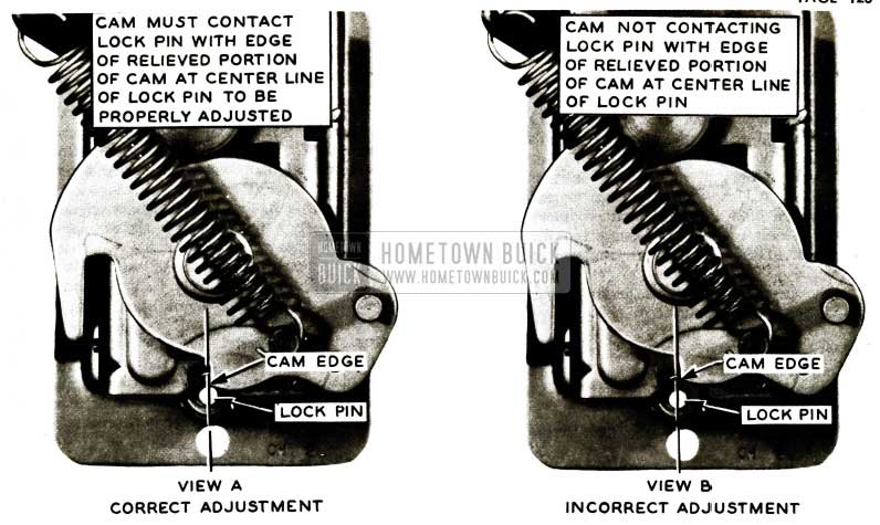
1956 Buick Air Conditioner Ranco Valve Adjustment
Further movement of the cam to the fully closed position will lock valve closed. CAUTION: This adjustment should only be at room temperature or not lower than 70° otherwise, proper adjustment will not be obtained.
NOTE: This adjustment should be made only after all corrections outlined in BPS 2.409 have been completed.
Left Outside Air Vent
- This valve must close completely to prevent air from entering the passenger compartment.
- This valve may be adjusted as required by moving the bowden cable sheath in or out of the sheath clamp just above the vent.
Air Distribution System
- The cooling efficiency of an air conditioner may be greatly reduced if cool air escapes at any connection in air distribution system other than at the air outlets. It is advisable to check for air leaks along the tubes and at all joint connections with blower on “Hi” and air conditioner turned on by placing hand at each connection. It is particularly important to check the rubber connector tube between the distributor duct adapter and the instrument panel center outlet valve adapter. Soma cases have been reported whereby only one of the spring clips holding the rubber connector (boot) to the distributor duct adapter has been used. Correct assembly calls for two (2) of these clips, one on each side. Also, if the rubber boot is cemented too high on the center outlet valve adapter, it will not allow enough rubber to mount onto the distributor duct adapter, causing an air leak. In some instances, the rubber connector (boot) was not cemented to the upper adapter, causing separation of parts.
- Another possible cause of insufficient cooling is restrictions in the air distribution system such as pinched hoses, collapsed tubes or adapters (see BPS 2.407 page 172). Make sure the tube from the air distributor duct to the left adjustable air outlets is of the correct length.
A few cases have been reported where the 50 and 70 series tubes (48 1/2 inches long) were used on 40 and 60 series cars (42 1/2 inches length specified), causing a kink in this hose directly behind left instrument air outlet.
A quick visual inspection will tell you if the standard hose instead of the correct insulated hose is used between the blower and the defroster core outer housing, it is also important that the outer housing be insulated with the correct insulation material as it is furnished with each air conditioner field installation package. Body undercoat will not do. Another important thing to remember is that maximum cooling will always take place when the air is dry. During hot humid weather, the air conditioner acts as a dehumidifier and cooling is lost in the condensed liquid which drains out the drain pipes.
ENGINE OVERHEATING ON AIRCONDITIONED CARS
A recommended procedure for determining the cause on cars which are overheating is listed below.
- Make certain that pressure is held in cooling system by using a known good radiator cap or check cap with an AC pressure cap gauge if available. 1956 non-air conditioned cars should be equipped with a 7 lb. cap and air conditioned cars with a 13 lb. cap. If air temperatures above 110°F are expected, a 13 lb. cap should be installed on a non-air-conditioned car to permit higher temperatures before coolant is lost.
- Check tension of fan belts. Engineering is recommending that the compressor belt adjustment be made with a torque wrench at the generator pulley. Tighten belts until 25 to 30 ft. lbs. of torque slips generator pulley on belts. This method provides the desired belt tension and assures maximum air circulation in engine compartment.
- Make certain there is no undercoating on radiator lower tank or core.
- Make certain Air Conditioner is not overcharged and that it does not have air in the system.
- Make certain engine timing is not retarded past T.D.C.
- Clean radiator to remove bugs, dirt, etc.
- On air conditioned cars clean condenser to remove bugs, dirt, etc.
- Be sure that the anti-freeze has been drained from the cooling system (radiator and engine block) for summer operation.
- After the above basic checks have been made road test the car to determine if the cooling system is operating correctly by driving the car 3 to 4 miles to warm it up and then driving at a steady speed of 30MPH. At an air temperature of 80°F the water temperature gauge hand on either an air-conditioned or non-air conditioned car should be at the start of the letter “N”. At an air temperature of 110°F the hand should be at the start of the red area. For air temperatures between 80°F and 110°F the location of the hand should be proportional.
- If test 6 indicates the coolant temperature is too hot, clean the inside of the radiator and the water passages of the engine (crankcase and cylinder head). Plugged radiators from core sand, cast iron particles, solder, etc. have been reported. Also, in a few cases it has been found that the cylinder head gaskets were leaking, allowing hot exhaust gases into the cooling system. This can be diagnosed easily by observing air bubbles in the radiator during engine operation.
- The spacing between the condenser and the radiator averages 1 – 1 1 /2”. This dimension was determined by actual tests to be the best value for both cooling and air conditioning, so it is undesirable to use other spacing.
- On 1956 air conditioned cars built before July 1, the water temperature gauge hand enters the red area at 205° F to cover boiling of winter alcohol water mixtures. Since water boils at 230°F with a 7lb. cap and at 243°F with a 13 lb. cap, the car can operate satisfactorily with the hand in the red area. It is only when the hand is at the upper end of the red area and water is lost that it is dangerous to operate the car. Gauges without the red area will be available under Gr. 1.148 Part #1513392 at all warehouses approximately August 1, 1956 for installation on air conditioned cars with the overheating complaint. All air conditioned cars manufactured after July 1 have the red area on the water temperature gauge omitted.
- If the car is being operated in temperatures above 100° it may be necessary to increase the cooling system air flow by installing the six-bladed fan Gr. 1.359 Part #1161825 which is available through Buick Parts Warehouses.
- If the car is going to set in one position for any length of time with the air conditioning operating, the owner should be instructed to put the transmission in Neutral or Park position. Leaving the transmission in Drive or Low and raising the engine speed above idle to maintain flow of cold air from the air conditioned system causes the transmission to pump a tremendous amount of heat into the engine cooling system and will cause overheating.
- If the car is being driven in heavy traffic with most of the time spent stopped or moving very slowly, then the transmission should be put in Low. This will increase the engine speed and hence air flow and water flow rates during portion of time car is moving and assist in maintaining cool water temperatures.
Leave A Comment
You must be logged in to post a comment.