SPARK PLUGS
All 1956 models will be equipped with the AC 44 type spark plugs. However, if more severe operating conditions are anticipated (high speed driving) for prolonged periods of time, it is recommended to install a cooler plug, AC 42 Commercial. The spark gap setting for either plugs remains the same, 30-35.
If the AC 42 Commercial plug is used on 1955 models, the 1956 spark plug boot must be used.
T-3 HEADLAMPS
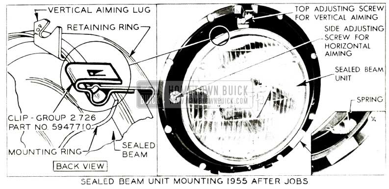
Installation and Aiming of T -3 Headlamps on 1955 After Jobs – Whenever T -3 headlamps (sealed beam units) are to be installed on a 1955 after job having the type of “Sealed Beam Unit Mounting” shown in Figure 82 , a spring clip (retainer ring to mounting ring clip), Group 2.726, Part #5947710 should be permanently installed as indicated.
1956 Buick Sealed Beam Headlamp Mounting
This clip will hold the sealed beam unit firmly against the retainer ring and mounting ring so that all three (3) parts are held securely together when the T -3 Safety-Aimer is attached. If the clip is not used, these three (3) parts tend to separate, making it impossible for Aimer to be held solidly in a stationary position to accurately aim T -3 headlamps.
NOTE: All other past model sealed beam unit mountings need not have the clip installed to accurately aim T -3 headlamps with Safety-Aimer.
Safety- Aimer is designed to be used only when both T -3 lamps are installed. If only one T -3 lamp is installed on a car equipped with old type sealed beam units, it will be necessary to aim the lamps as described in BPS 2.384.
Each dealer who has ordered a Guide T -3 Safety Aimer will receive twenty (20) of the above mentioned clips with each Aimer.
Additional supply of clips will be made available through the Parts Department and may be ordered under the group and part number previously mentioned which consists of a package containing ten (10) clips.
The following procedure will be helpful in obtaining an accurate aim of the T -3 headlamp.
Upon attaching the T -3 Safety Aimer to a headlamp equipped with Guide T-3 Sealed Units, first properly latch the bottom hook, then either of the two remaining upper hooks.
To remove the T -3 Safety Aimer, unlatch the upper two hooks first and last the lower hook.
GROUNDED REGULATORS
It has been brought to our attention that on some generator regulators, the ground wire screw is too long, causing it to contact the resistor and ground out the generator field. See Figure 83.

1956 Buick Grounded Regulators
This condition is further aggravated if the resistor is not positioned properly during manufacturing. In any event, if the generator field is grounded as described above, the generator output may exceed its maximum operating values and eventually burn out the generator.
Flint production has encountered same difficulty with series 40-60 voltage regulator mounting plates: These plates were being bent prior to the assembly of the regulator. This causes the generator field to be shorted out through the mounting plate with the same effect as described above.
It is, therefore, suggested to check the above conditions on all voltage regulator and generator complaints. If the first condition exists, the screw should be cut off to eliminate the interference. If the second condition exists, the mounting plate should be straightened to provide clearance to the regulator.
T-3 AIMER CHANGES
Because of the many changes and additions to the safety-aimer since it was first adopted, the following information was compiled to eliminate any confusion that may exist regarding its use.
- The first change in the use and procedure of the T -3 safety-aimer was the use of the retainer clip which is to be used on the 1955 after jobs having the type of “Sealed Beam Unit Mounting” shown in Figure 84.
1956 Buick Aiming Dial Guide T -3 Safety-Aimer
The spring clip (retainer ring to mounting ring clip) Gr. 2726 Part #5947710 should be permanently installed as indicated in Fig. 84. This clip will hold the sealed beam unit firmly against the retainer ring and mounting ring so that all three (3) parts are held securely together when the T -3 safety-aimer is attached. If the clip is not used, these three (3) parts tend to separate, making it impossible for the aimer to be held solidly in a stationary position to accurately aim T -3 headlamps. NOTE: All other past model sealed beam unit mountings need not have the clip installed to accurately aim T -3 head lamp with safety-aimer. Safety aimer is designed to be used only when both T -3 lamps are installed. If the car is not equipped with two (2) T -3 lamps but with one or both lamps of the old style, the lamp will have to be aimed according to the procedure outlined in BPS 2.384.
How to Install Aiming Dial
Guide T -3 Safety-Aimer
The safety-aimer is calibrated at the factory in such a manner that when the bubble in the aimer level is between the center two markings as shown in Figure 10-9 of the 1956 Product School Manual, the instrument is calibrated to provide the standard two inch drop in head lamp beam light per 25 feet.
In order to install the aiming dial shown in Fig. 84 it will be necessary to disturb this factory calibration; therefore, it is important that some means be provided for recalibrating the fixture to the factory setting after the aiming dial has been installed. In order to do this, the factory calibrated T -3 aimer should first be placed on any vertical wall surface that will center the bubble as shown in Fig. 10-16 of the Product School Manual. It may be necessary to locate separate reference points for each aimer due to manufacturing variations. Mark reference location for each aimer so that each may be recalibrated to original factory setting after installation of aiming dial.
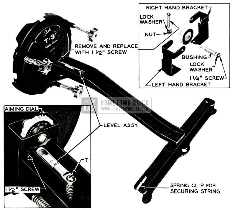
- Remove the screw on the level assembly nearest the base plate, and replace it with the 1 1/2″ screw furnished. Tighten screw until 3/8″ of the screw extends through the bottom of the support aim nut. See Figure 84.
- Assemble right hand bracket to the support arm over 3/8” extension of screw assembled in Step 1. Next, assemble left hand bracket to the support arm over 3/8″ extension of same screw as used for right hand bracket, and secure with lock washer and nut.
- Insert bushing into aiming dial.
- Mount the aiming dial assembly between the left hand and right hand brackets and secure with lock washer and 1 1/4″ screw. See Fig. 84. IMPORTANT: When the parts are assembled, the 1 1/2″ screw head must not bottom the level assembly when the dial is rotated to line up the numeral 2 with the pointer.
How to Calibrate the Level
- Set the dial so the numeral 2 aligns with the pointer on each aimer.
- Place aimers on vertical wall reference points originally selected and marked, which exactly centered the bubbles on the aimer.
- Center the bubbles on each aimer by turning screw “T” in the proper direction.
- Each T -3 safety-aimer is now adjusted to the original setting as you received it from the factory OR if you have calibrated your aimers for a particular aiming area, they are now properly adjusted for that area.
How to Aim Headlamps Horizontally
For aiming headlamps horizontally there are no changes in instructions given on Page 6 of the Original Instruction Book.
How to Aim Headlamps Vertically
- To aim headlamps of passenger cars, rotate the vertical aiming dial so that the numeral 2 is at the top of the dial and in line with the pointer. This will aim the upper beam 2 ” below the level of the lamp centers at twenty-five (25) feet. This aim is approved by all states for passenger cars.
- To aim the headlamps of vehicles other than passenger cars, make the selection of “inches in down aim” required, such as 4, 5, 10, etc., then rotate the vertical aiming dial so that the numeral selected appears at the top of the dial in line with the pointer. Now proceed in accordance with the aiming instructions shown on Page 7 of the Original Instruction Book.
(To make the proper selection of ”inches in down aim” required for vehicles, check your local or state regulations governing headlamp aiming).
CAUTION: When this device (guide T -3 safety aimer, Adapter Package) with the adjustable dial feature is used in an official state headlamp inspection station for headlamp aiming, its use should be clarified with your state inspection authorities for complete lamp inspection requirements.
T-3 HEADLAMP TIPS
A few reports have been received of defective aiming tips on some of the new T -3 Sealed Beam Units due to the tips being of different lengths. The tips will not always be of the same length and a unit should not be considered defective due to different lengths of tips. The length of tip may vary on any one sealed beam unit, as the length it is ground to in manufacturing is determined by the location of the filament in the bulb. The grinding operation is adjusted electronically so the tips will accurately position the T -3 aiming tool during the aiming procedure.
The question of the flat surface on the end of the tip is very important; this surface determines the location of the aiming tool. In order to effectively position the aiming tool, the tip must have a flat surface approximately one-half the diameter of the original ground surface. Any units with tips that are sharp or jagged cannot be used to properly aim the lamps. Tips that are broken will also render the unit useless for aiming with the T -3 aiming tool; in these instances the screen type aimer must be used.
HEADLIGHT SWITCH KNOB RATTLE
1956
Light switch knob rattling against the escutcheon on the instrument panel has been reported on a few 1956 cars. This was found to be caused by the switch bracket in back of the instrument panel being out of alignment with the knob and rod assembly.
The method of correcting this condition is as follows:
- Disconnect battery ground cable from post on battery.
- Pull switch knob out to last notch. Then reach up under the instrument panel and depress the spring loaded latch button on switch while pulling the knob and rod assembly out just far enough to clear the instrument panel knob escutcheon.
- Bend the switch mounting bracket in back of the instrument panel to center the switch knob and rod assembly in the instrument panel escutcheon.
- Push knob- in so it locks in place.
- Connect battery ground cable and use care to properly wind the clock as outlined in the 1955 Shop Manual (par. 10-56).
NEW GENERATOR
35-Ampere Generator and Voltage and Current Regulator, and Nylon Insulated Generator Armature Coils
1956 – All Series
Effective at the start of 1956 production, a generator (Gr. 2 .275, Part No. 1102051) will be used on air condition equipped cars. This generator is capable of delivering 35 amperes at 14 volts. It will be used with a 35-ampere voltage and current regulator, Gr. 2.500, Part No. 1119162. This generator can be further identified by the large 5.4 inch diameter fan and by the reservoir type oiling system at the commutator end. The proper voltage and current regulator may be quickly identified by a Black stripe of paint on the mounting bracket near the part number.
At the start of 1956 production, cars without air conditioning will be equipped with 30-ampere generators, Gr. 2.275, Part No. 1102005, and 30 -ampere voltage and current regulators, Gr. 2 .500, Part No. 1119003.
About January 1, 1956, the cars without air conditioning will be equipped with 35 -ampere generators, Gr. 2.275 Part No. 1102053, and35-amperevoltage and current regulators, Gr. 2.500 Part No. 1119162. These generators may be further identified by the large 5.4 inch diameter fan. They will have the conventional wick type oiler. The regulator is identical to the regulator used on all 1956 air condition equipped cars.
The proper voltage and current regulator must be used with the proper generator. Substitutions must not be made or early generator failure will result.
If service adjustments are necessary on the current regulator unit of the Gr. 2 .500, Part No. 1119162 voltage and current regulator, it should be adjusted to 32 to 38 amperes (hot) using the method outlined in the 1955 Shop Manual. These values must not be exceeded or early generator failure will be experienced due to generator overheating. The specifications on the cut out relay, voltage regulator, air gaps, and point openings are the same as outlined in the 1955 Shop Manual for the 1118825 voltage and current regulator.
In order to continue the field test on generator armatures having nylon insulated coils in place of cotton insulated coils, some of the Gr. 2.275, Part #1102053 generators from the Flint Plant only will have nylon insulated armature coils.
These generators can be identified by the letter ”N” stamped on the generator frame adjacent to the name plate. The nylon insulated armatures will have the Part No. 1935277 stamped on the armature laminations.
If a 1935277 nylon insulated armature should fail in service, production armature, Gr. 2 .279, Part No. 1932900, now stocked by the Parts Department, may be used as a replacement. All defective nylon insulated armatures should be properly tagged and returned to the attention of Mr. V. 0. Wirt, through your local zone, in a shipment separate from other warranty material with a letter stating how and when parts were shipped.
The Return Parts Tag should be properly filled out, including model, serial number, mileage, delivery date and any information that is available, relative to armature failure with any additional comments deemed necessary. It will not be necessary to submit special reports unless circumstances warrant them.
TRUNK LIGHT INOPERATIVE
Trunk lights should light, when opening the trunk lid, at a point of from eight to ten inches before the lid is fully open. If the light does not come on at this point, bend the lamp assembly bracket forward until the mercury switch makes contact and lights the bulb. Conversely, if the bulb lights at a point before the lid is raised to the above described height, the bracket should be bent rearward.
NEW STARTER RELAY
Recently Engineering notified us that they had approved a new starter relay to replace the first type relay Gr. 2.127 Part #1116876. The new starter – relay Gr. 2.127 Part #1116921 will be made water tight by dipping it in vinyl plastic. This process of water-proofing will be used until nylon inner and outer insulators can be added.
SIGNAL SWITCH STICKS
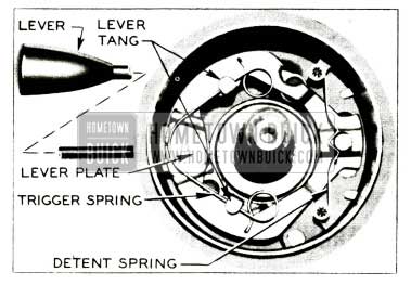
We have received a few reports that the trip mechanism in the signal switch housing on some 1956 models stick, and does not return to center on “off” position after a turn is completed. This may be caused by the switch centering pins on the steering wheel hub being bent or the trigger spring, shown in Figure 85, hanging up on the lever plate due to burrs under the tangs.
1956 Buick Signal Switch Stick Repair
To correct this condition, the following is recommended:
- Remove steering wheel and check the centering pins for straightness.
- Remove the trigger spring and sand off any burrs under the tangs using a piece of emery cloth.
- Lubricate the trigger spring with lubriplate and reassemble, making sure spring operates freely in the tangs.
- Reinstall steering wheel.
GEN. VOLTAGE & CURRENT REGULATOR CHANGE
1956
Supplementing the new generator information in BPS 2.397 dated November 23, 1955, we have been advised that approximately the end of February, a new 35 ampere generator Gr. 2.275 Part # 1102053 will be used on all 1956 cars without air conditioning.
Improvements have been made in the field coils of this generator as well as the 35 ampere generator, Gr. 2.275 Part #1102051, used on all air conditioned cars, in that lower resistant field coils are used to obtain higher output at low speeds.
In addition to the above change a new voltage and current regulator, Part #1119168 will also go into production to replace model 1119162 regulators. The new regulator, Part #1119168 has an 80 ohm regulating resistance in place of 130 ohm used in the 1119162 regulator.
The present regulator Part #1119162 will work satisfactorily with either generator and the adjustment procedure for both regulators is the same as covered in the 1956 Shop Manual.
The Parts Department will continue to carry regulator Gr. 2 .500 Part #1119162 as a service replacement for both #1119168 and 1119162 regulators.
DIRECTIONAL INDICATOR LIGHT CHANGE
1956 Models
Shortly after the start of 1956 production a change was made in the directional signal indicator pilot light, particularly the left pilot light, to give greater illumination so that it may be observed even in bright sunlight. A No. 57 (2 candle power) bulb, Gr. 8991, Part #273157, was used in place of a No. 53 (1 candle power) bulb, Gr. 8991, Part # 131282, in these locations. In addition, the inside of the left indicator bulb housing was painted with flat white paint.
If complaints of this nature are received on early 1956 cars the above change can be made as follows:
- Disconnect battery cable.
- Lower the fuse block to reach the left indicator bulb housing.
- Remove two retaining screws in the bulb housing with a short screw driver, (preferably with a large handle).
Note: For reinstallation a keeper type screw driver is helpful.
- Paint the inside of the left bulb housing with a flat white paint.
- Install the No. 57 bulbs in both the left and right indicator pilot light housing.
Note: To replace the right direction signal indicator pilot light or any of the cluster lights, it is best to reach up on the right side of the steering column for removing and installing the sockets.
When reconnecting battery cable make sure to give the clock its initial wind as outlined in the
1955 Shop Manual, Paragraph 10-56, sub. par. b.
BURNED DISTRIBUTOR ROTOR TIPS
If a distributor rotor on a 1956 car is badly burned on one corner of the tip, the distributor cam should be examined to determine if the proper breaker cam is installed.
Following is the method to follow in order to determine whether or not the distributor has the proper breaker cam installed.
- Remove the rotor.
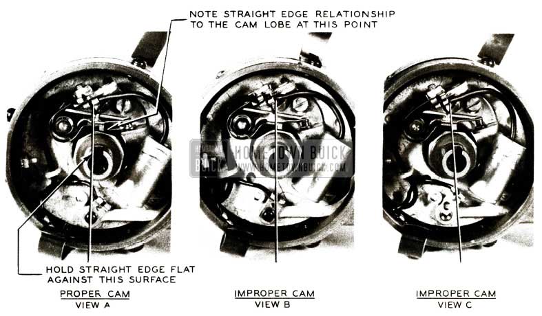
- Hold a straight edge (a 6″ steel rule is satisfactory) flat against the counter clockwise edge of the rotor positioning slot and angling down towards the breaker cam.
- Note the relationship between the edge of the straight edge and the nearest cam lobe.
- Compare this relationship with Figure 86.
1956 Buick Distributor Rotor Tips
View A, Figure 86 shows the proper relationship between the rotor positioning slot and the breaker cam lobe. Note that the straight edge is on the counter clockwise side of the nearest cam lobe.
View Band C, Figure 86 show improper relationship between the rotor positioning slot and the breaker cam lobe. Note that the straight edge is on the clockwise side of the nearest cam lobe.
The use of distributors shown in Views Band C could cause the following difficulties:
- Cross Firing
- Rapid burning of the rotor tip
- Possible detonation
- Timing difficulty
The breaker cam assembly must be replaced in distributors having the breaker cam conditions shown in Views B and C.
SPEEDOMETER REMOVAL
If it becomes necessary to R&R a 1956 speedometer head for any reason, one procedure that has been used satisfactorily is listed as follows:
- Disconnect battery.
- Disconnect defroster hose from left windshield defroster outlet duct and pull hose out of the way.
- Disconnect the heater-defroster control panel from the under side of the instrument panel and lower unit out of the way.
- Remove radio from behind instrument panel.
- Remove left radio bracket.
- Disconnect fuse block from bracket and lower out of way.
- Disconnect combination lighting and instrument light switch from instrument panel and lower out of way.
- Disconnect temperature gauge from rear of instrument cluster assembly and move out of way.
- Disconnect all light bulbs, gauge wires and lines from rear of instrument cluster assembly.
- Disconnect speedo cable from cluster assembly and speedo reset from lower section of instrument panel.
- Remove instrument cluster assembly from behind instrument panel.
- Remove gasoline gauge from cluster assembly.
- Remove ammeter gauge from cluster assembly.
- Remove oil pressure gauge from cluster assembly.
- Remove speedometer head from cluster assembly.
To replace speedometer head, reverse above procedure. If the speedometer head is to be left out of the car and reinstalled at a later time, the same steps will be taken to replace the cluster assembly as listed above, except that the speedo cable and speedo reset will not be attached at this time.
The total time to remove and replace a speedometer head as a single operation (Oper. 12-230) is 2 .2 hrs. The total time to remove a speedometer head and replace the instrument cluster assembly when the speedometer head has been sent out for repair is 2.2 hrs. (Oper. 12-231). The total time to remove the instrument cluster assembly and replace the speedometer head after it has been repaired is 2.2 hrs. (Oper 12-232).
BRAKE WARNING LIGHT SWITCH SHORTS
It has come to our attention that on some 40 and 60 series cars there is insufficient clearance between the terminals on the emergency brake warning light switch and the bottom edge of the instrument panel. Although the switch connections are covered with an insulator, this insulator will chafe through when rubbing against bottom edge of instrument panel, causing a short circuit. Whenever this condition is encountered it is suggested that the switch be rotated in the mounting bracket so that the terminals are parallel to the bottom edge of the instrument panel or until there is sufficient clearance to eliminate this condition.
This may be accomplished by disconnecting the switch and bracket assembly. Then with the switch out of the car, using a pair of pliers, rotate the switch in the desired direction. NOTE: While rotating the switch grasp it as close to the mounting bracket as possible and only apply enough pressure on the pliers to hold the switch secure. Excessive pressure will distort the switch housing.
Note: Following is a list of parts necessary to install Brake Warning Lights on 1956-40-50-60 series cars not originally equipped.
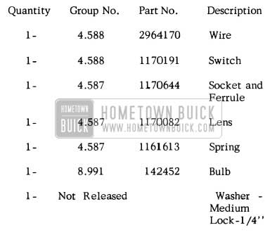
1956 Buick Brake Warning Lights Parts
Leave A Comment
You must be logged in to post a comment.