ENGINE SPECIFICATION
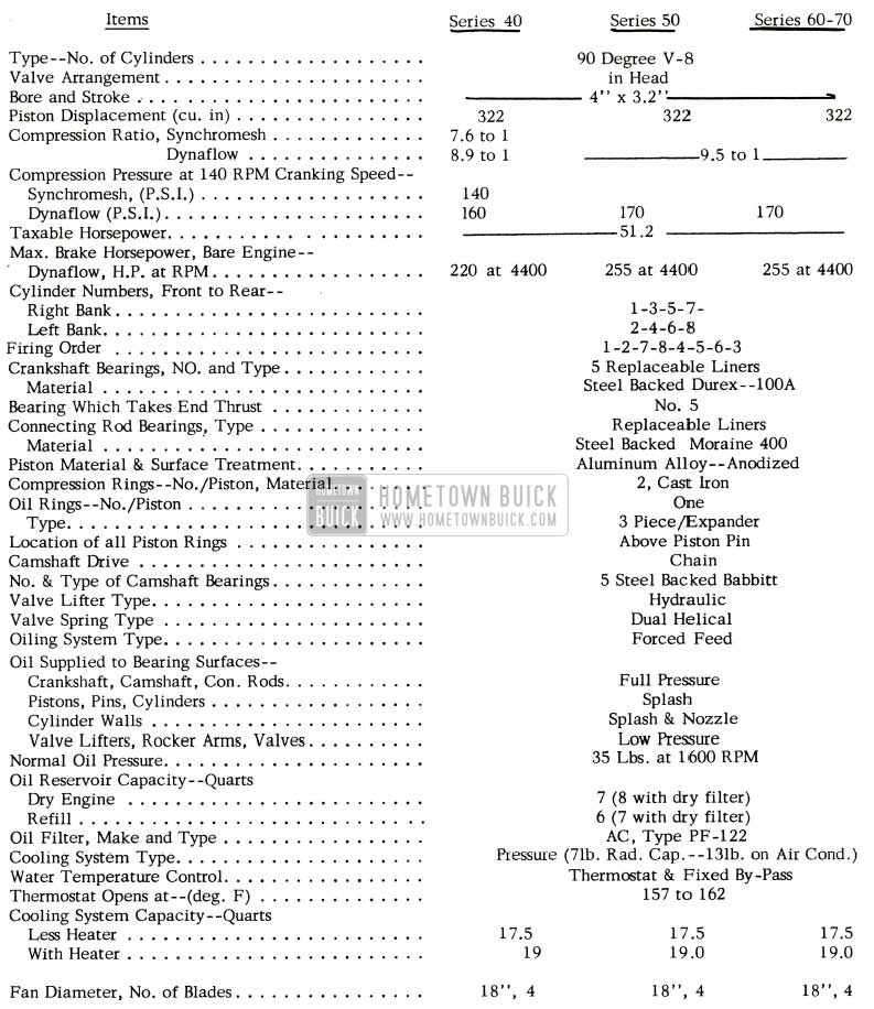
1956 Buick Engine Specification
ENGINE ASSEMBLIES
The following engine assemblies will be available for direct shipment to dealers from Flint:
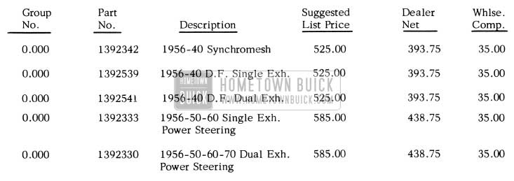
1956 Buick Engine Assemblies
These engines do not include the air cleaner, generator, generator brace, ignition coil, distributor cap and wires, fan, fan driven pulley, fan hub, fan spacer, fan driving pulley and spacer, fan belt, throttle linkage and dash pot which must be transferred from the old engine.
The 50-60-70 engines include the power steering gear oil pump mounting bracket which must be removed on a 60 series if it is not equipped with power steering. When removing this bracket on a 60 series, it will be necessary to use a standard short cylinder head bolt, Group 0.293, Part No. 1342898 at the left front outer location. The 40 series engines are supplied, less the power steering pump mounting parts, which must be transferred from the old engine.
Since the 1953-1954-1955 V-8 engines are out of production, the Parts Department will not stock these engines. If a complete V -8 engine is required for a 1953, 1954 or 1955 car, the 1956 engine can be used in certain models with certain modifications as follows:
1954-1955-40 D. F.
The 1956 Engine #1392539 can be installed by making the following changes:
- Remove the following from the 1956 engine.
- Water Pump
- Water Manifold
- Right and Left Exhaust Manifolds
- Timing Chain Cover
- Remove the following parts from the 1954 or 1955 engine and install them on the 1956 engine.
- Water Pump
- Water Manifold
- Right and Left Exhaust Manifolds
- Timing Chain Cover
Balance of parts as listed above must be transferred from old engine.
1955-50-60-70 D.F.
The 1956 Engine #1392333 can be installed by making the following changes:
- Remove the following parts from the 1956 engine.
- Water Pump
- Water Manifold
- Right and Left Exhaust Manifolds
- Timing Chain Cover
- Remove the following parts from the 1955 engine and install them on the 1956 engine.
- Water Pump
- Water Manifold
- Right and Left Exhaust Manifolds
- Timing Chain Cover
Balance of parts as listed above must be transferred from old engine.
1954-50-60-70 D.F.
The 1956 Engine #1392333 can be installed by making the following changes:
- Remove the following parts from the 1956 engine.
- Water Pump
- Water Manifold
- Right and Left Exhaust Manifolds
- Timing Chain Cover
- Remove the following parts from the 1954 engine and install them on the 1956 engine.
- Water Pump
- Water Manifold
- Right and Left Exhaust Manifolds
- Timing Chain Cover
- Install the following new parts on the 1956 engine.
- Group 3.402 – 1552426 – Air Cleaner
- Group 3.430 – 1162451 – Carburetor Throttle Operating Rod (Series 50 only)
Balance of parts as listed above must be transferred from old engine.
1953-50-70 D.F.
The 1956 Engine #1392333 can be installed by making the following changes:
- Remove the following parts from the 1956 engine.
- Right Exhaust Manifold
- Right Engine Mounting and Generator Mounting Bracket
- Left Exhaust Manifold
- Oil Pan
- Oil Pump Screen, Housing and Cover
- Oil Gauge Rod
- Starter
- Water Pump
- Water Manifold
- Timing Chain Cover
- Remove the following parts from the 1953 engine and install them on the 1956 engine.
- Right Exhaust Manifold
- Right Engine Mounting Bracket
- Generator Mounting Bracket
- Generator Mounting Brace
- Left Exhaust Manifold
- Oil Pump Screen, Housing, Inlet and Cover
- Oil Pan
- Oil Gauge Rod
- Starter
- Water Pump
- Water Manifold
- Timing Chain Cover
- Install the following new parts on the 1956 engine.
- Group 1.159 – 1163095 – Radiator Inlet Hose
- Group 3.402 – 1552426 – Air Cleaner
- Group 2.239 – 2964949 – Ignition Cable Set
- Group 3.430 – 1345350 – Carburetor Throttle Operating Rod (Series 50 only)
Balance of parts listed above must be transferred from old engine.
The 1956 Synchromesh Series 40 engine cannot be used in 1954 and 1955 engines so there will be no engine assemblies available for these models. If a complete engine is required for the 1954 and 1955 Series 40 Synchromesh, it will be necessary to order the separate parts.
Since there are no Synchromesh engines for the 1956-50-60 models, there will be none available for use in past models. However, the Parts Department has a limited supply of the 1955-50-60 Synchromesh Engine No. 1392166 on hand. This engine can be used in the 1953-50; 1954-50-60 Synchromesh cars as shown in B.P.P.I. No. 54-42, dated 11-30-54. When this supply is exhausted it will be necessary to order the separate parts.
PISTON FAILURE
We have received a few reports of piston failures wherein a subsequent piston would fail on the same job with very little operation. When a piston fails, parts from that piston can travel through the inlet manifold into three other cylinders and cause the subsequent piston to fail.
To prevent this condition from reoccurring, thoroughly clean the inlet manifold and both cylinder heads before reassembling an engine after a piston failure.
IDLE VACUUM
1956 Buick Engines
Idle vacuum values on all 1956 Buick engines (Dynaflow and Synchromesh) should be 15.5 to 16.5 inches of mercury with engine idling at 450R.P.M. This is lower than past models and is caused by engine design and does not indicate failure of valves.
Therefore, if engine is free of vacuum leaks, reconditioning of cylinder heads is unnecessary unless idle vacuum is below 15.5inchesofmercury.
CAMSHAFT IDENTIFICATION
All camshafts in 1956 are made of a cast iron alloy and not to be used with any past model distributor gears or valve lifters because the materials are not comparable. Neither should past model camshafts be used with 1956 lifters and/or distributor gears for the same reason. 1956-40 Series Synchromesh equipped cars have camshafts identified by a plain land just forward of the number 3 Bearing Journal. All other camshafts have 2 grooves in this land as indicated below. See Figure 1.
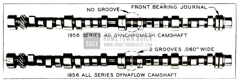
1956 Buick Camshaft Identification
WATER PUMP COVER BOLT TORQUE CHANGE
We have been advised by our Engineering Department that the water pump cover attaching bolt torque specification has been reduced from 12-15 ft. lbs. to 6-8 ft. lbs. to prevent the possibility of these bolts being damaged. It is, therefore, suggested that the torque specification for these bolts listed on Page 2-1 of the 1956 Shop Manual, be changed to read 6-8 ft. lbs.
WATER PUMP REPAIR
1956
It has been brought to our attention that some dealer service personnel are trying to eliminate water pump noise by only replacing the seal kit.
Our Engineering Department recommends that whenever complaints of water pump noise are encountered in the field, both the seal kit, bearing and shaft assembly be replaced. However, if the water pump is being overhauled because the seal is leaking, only the seal need be replaced; but the bearing and shaft assembly should be checked to make sure it is not damaged. If the bearing and shaft assembly shows evidence of rust, roughness, or if bearing is loose on shaft, then only should it be replaced.
FAN SPACER
It has been found that the counter bore in the engine fan spacer is too shallow. In some cases the fan driven pulley is not clamped against the water pump hub when the fan is installed. This causes cracking of the fan driven pulley. This could also cause the fan to be cocked with a resulting fan out of balance.
When replacing a fail fan driven pulley, the installation should be checked to determine if the fan spacer is clamping the fan driven pulley against the water pump hub. If the fan spacer does not clamp, the counter bore in the spacer should be deepened to 3/8″ with a 5/8″ reamer, to provide clearance for water pump shaft.
VIBRATION COMPLAINTS
Due to the increase in number of reports received concerning various types of vibrations, we have prepared this bulletin in an effort to point out all possible items that can contribute to such a complaint and to establish a systematic procedure for diagnosing it. The information given below may be used in its entirety or only in portions, depending upon the nature of complaint.
Due to the complexity of this problem, we will handle each component of the car separately in an effort to systematically eliminate each component and pin-point the source of trouble. Often, when a complaint of vibration or roar is encountered, a great deal of time will be saved by checking the history of the vibration and the car. If the vibration developed after service work of some type was performed, then this would be a likely spot to start looking for the vibration. NOTE: When diagnosing vibrations it is advisable to use a tachometer to determine the engine speed at which the vibration occurs.
When diagnosing a vibration complaint, first drive the car and determine at what car speed and engine rpm the vibration appears. When driving the car, shift from drive to low to determine if the roar or vibration is present at the same car speed or at approximately one-half the car speed. When the noise is present at the same car speed the source of trouble is in the drive line or chassis suspension. If the roar or vibration appears at one-half the car speed, this is an indication that the roar or vibration is related to one or more of the engine components or transmission converter. This may be verified in the mechanic’s stall by running the engine up to the critical speed with the transmission in neutral. NOTE: Drive range may be used for a short time if a light load is required to cause the roar or vibration to be noticed.
At this point it should be determined whether the condition that exists is actually a vibration or the part throttle roar which is more commonly experienced. This can be accomplished by running the engine at 1400 to 1600 rpm with the transmission shift lever in drive range or low range, whichever will give the desired rpm, and the car held stationary. If the roar is present at this speed, this is an indication that the noise is the part throttle roar and not an out-of-balance condition. If this roar condition exists, precede to the section covering engine fuel and exhaust described below.
ENGINE FUEL AND EXHAUST
Sometimes a vibration or roar can be traced to the exhaust system of a car. This condition may be easily detected since it has a direct relation to engine speed whether the car is in motion or not. The critical engine speed for this roar is generally at 1400 to 1600 rpm and under part throttle loads. The following items may contribute to this complaint:
- Check the entire exhaust system to make sure it is free of leaks and that the system is free to move without interference with the frame or body.
- If the car has been undercoated, make sure the muffler, tail pipe, and mounting brackets do not have any undercoating on them.
- Make sure that the muffler is in good condition with no dents or loose baffles.
- Check exhaust manifold heat valve for correct operation.
- Remove bracket ahead and behind the muffler and check for roar. If the roar decreases, this is an indication that there is a bind at this location and extreme care must be used when reinstalling the brackets.
After these items have been eliminated as possible sources of trouble, and the roar persists, it may help to completely loosen and realign the entire exhaust system. Also, it often helps to use two new gaskets at the exhaust manifolds and “Y” junction to provide more flexibility to the exhaust system on 1955 and earlier models. It is impossible to tell if the exhaust system is misaligned by a visual inspection.
ENGINE
When it has definitely been established that the roughness or vibration is in the engine, make sure the engine is properly tuned and adjusted; also check the following:
- Make sure the spark plugs are clean and gapped properly.
- Test compression pressure in all cylinders, using reliable pressure gauge.
NOTE: Pressure variation among cylinders should not exceed 15 lb./sq.
- Check carburetor idle adjustment and make sure that throttle linkage is adjusted properly and operates freely.
- The air cleaner and silencer must be properly assembled. NOTE: Silencer for four barrel carburetor must be free from leaks and must not have dents in silencer chamber; these conditions can create a sound which may be mistaken as an exhaust roar. The joint between air cleaner cover and oil base must be properly vent noise leaks at this point. Silencer should be free from rattles and should not contact hood.
- Make certain that valve lifters are working properly and that valve mechanism is receiving sufficient lubrication.
- Make sure that the engine is free of vacuum leaks and that vacuum at 450 rpm is within factory specifications (15 1/2 to 16 1/2 inches of mercury – all 1956 series).
If any of the above are not satisfactory, correct them and check if the vibration decreases. If the vibration is still present, disconnect all drive ”V” belts. By doing this the water pump, generator, power steering pump, fan, shroud, and air conditioner compressor, if the car is equipped with one, can be eliminated as the possible sources of trouble. CAUTION: Engine should not be operated too long without “V” belts.
Before proceeding any further, check the harmonic balancer to see that it is not loose on the crankshaft and that it is in satisfactory condition (no loose rivets, pulley cracked or excessive runout). A new balancer may be substituted for trial if original balancer is suspected of causing source of trouble.
While the “V” belts are disconnected check the operation of the water pump for smooth bearing operation. Also check the fan to see that there are no bent blades. Naturally, if either of these items appears to be defective, it must be replaced. There are a few cases where none of the above suggestions will affect a change but these cases are in the minority. If you should encounter an engine in this condition, it may be balanced by following the directions outlined in paragraph 2-27 of the 1955 or 1956 Shop Manual.
In the event improvement cannot be made by adding, subtracting or moving balance weight at the flywheel, it is suggested the weight be added to the balancer to determine if an unbalanced condition exists at front end of crankshaft. This may be accomplished by placing putty inside of fan driving pulley at various locations and running engine. If an improvements is noticed at a certain point, the quantity of putty may be increased or reduced to eliminate as much vibration as possible. When location is found that reduces vibration, drill hole in balancer 180° from putty location. The amount of stock that should be removed from balancer by drilling, must be determined by weight of putty used and trial and error method.
We have covered two phases of engine vibration or roughness. First, roughness due to poor timing or an operational malfunction; second, roughness or vibration due to rotary unbalance. There is still a third cause for roughness – engine and transmission alignment. The correct method of aligning the engine and transmission is outlined below.
- Make a visual inspection of thrust pad, engine mount and transmission mount to see that they are not defective.
- Remove four front motor mounting lower nuts.
- Loosen two (2) transmission mounting pad stud nuts.
- Loosen three (3) transmission thrust pad stud nuts at front side of mounting. (See Figure 2)
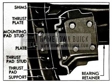
1956 Buick Transmission Mounting Pad Stud Nuts
TRANSMISSION
In addition to maintaining proper engine and transmission alignment, it is equally important to have proper alignment between “U” joint and torque ball. The universal joint or torque ball misalignment generally can be detected by its characteristic of setting up a vibration on a coast -down. If this condition is encountered it can be corrected by aligning the torque ball as outlined in BPS 2.397, Page 35. On 1955 or earlier model cars, check to see that torque ball is properly fitted and not excessively tight.
The transmission shift controls have been a source of noise and are highly resonant. If these controls are suspected, they may be corrected as outlined in BPS 2 .385.
An item that may be causing or transmitting noise is the clutch equalizer on standard transmission equipped cars. Make sure it has sufficient clearance and it is not binding in any way.
REAR AXLE
One of the most common sources of vibration in this component is in the propeller shaft. Propeller shafts that are out of balance will usually be noticed at higher speeds and will cause a tingling vibration in the body floor pan. This condition can be detected at approximately 65 mph and increases in intensity as the car load or speed increases. The vibration will increase if the trouble is the propeller shaft. A more detailed procedure for checking out-of-balance propeller shafts is outlined in Paragraph 7-7 of the 1955 and 1956 Shop Manual.
CHASSIS SUSPENSION
Probably the most prevalent type of vibration or noise is due to the tires. The methods for checking tire unbalance are thoroughly covered in Section 7-7 of the 1955 or 1956 Shop Manual. Another factor which may contribute to vibration is front end alignment, or incorrect caster, camber and toe-in can cause a low speed shimmy, which in some cases, may be diagnosed as a vibration. This shimmy will only occur below 30 mph. Other items that may cause this low speed shimmy are:
- low or uneven tire pressures
- loose front wheel bearings
- loose or worn steering knuckle bushings or king pins
- loose tie rod ends
- improperly adjusted or worn steering gear
In many cases a rough or brinnelled wheel bearing (front or rear) produces a vibration or growl which continues with car coasting and transmission in neutral. This noise will increase and decrease as the car is turned in one direction and then another, causing the load to be increased and decreased on the troublesome bearing. With car jacked up spin wheels by hand, while listening at hubs for any evidence of rough or brinnelled wheel bearings. Also, in connection with chassis suspension check to make sure the rubber insulators are used on the chassis end of the rear springs.
ELECTRICAL SYSTEM
Vibrations can be caused by any component of the car that rotates; therefore, the generator is a possible source of vibration. The generator may be checked very quickly by first making sure that it is mounted securely. Then, with one hand placed on the generator, run engine speed up from an idle to approximately 300 rpm. If the generator vibrates enough to create a noise in the car it will vibrate enough to be felt by the hand. As the engine is slowly speeded up, the generator might be felt to go into periods of vibrations at different engine speeds. The only way to correct a noisy or vibrating generator is to replace it.
Other items to check concerning the electrical system are:
- Are starter motor bolts torqued properly so they are not loose?
- Is the cranking motor shaft lever return spring properly connected? See Fig. 10-31 in 1955-56 Shop Manual.
- Insufficient clearance between the engine and starter splash pan.
BODY
Although the body does not have as many sources for vibration, it does tend to act like a sounding board or amplify some of the chassis vibrations. For this reason, there are a number of conditions that will require inspection and if necessary, correction. Following is a list of things to check:
- Is there proper clearance between body and chassis at all points? Check upper rear spring attaching bolt (see BPS 2.400), around wheel housing, over ”X” members and between front and rear bumper bars (seeBPS2.398), and body.
- Is the car undercoated? If so, extreme care must be exercised to insure that undercoating does not “short circuit” the body mounts or fill in clearance space.
- Are all body mountings assembled properly with even loading indicated at all points? Any mounting having the inner steel tubes collapsed should be replaced and properly torqued (25 to 30 ft. lbs.). Extreme compression on a few mountings only would indicate that the body should be reshimmed to balance load on mounts. NOTE: In no case should inner steel tube of mount contact frame.
- Check sheet metal at all fenders and bumpers by thumping with your fist to determine if it is loose or highly resonant. Correct by loosening, realigning and tightening.
- Are body fits in satisfactory condition? (doors, windows and chassis sheet metal).
- Make sure that the instruments are not transmitting noises.
- Be certain that all openings through dash are properly sealed and cables, rods and pipes are correctly insulated with rubber grommets or asphalt sealer.
After checking all these items, often an improvement can be made by performing the following:
- Loosen all body mountings, including those that extend into trunk compartment.
- On all jobs, except 1956 power steering equipped cars, loosen steering gear at frame to remove any misalignment, then retighten steering gear.
- Loosen mast jacket at instrument panel.
- Give car a good shake-down by driving over medium rough roads.
NOTE: All points mentioned above must be loose during shake -down except steering gear at frame.
- After shake-down, loosen steering gear at frame and then tighten all points. The body should rest firmly on all mountings before bolts are tightened, and steel shims should be added where body does not contact a mounting. Shims for this purpose are furnished under Group 9.023.
- Realign steering gear and tighten.
REDUCING OIL FLOW TO VALVE TRAIN
Following is a reprint of Special Red Band Service Letter, Dealer No. 177 – SUBJECT: Reducing Oil Flow to Valve Train – All V-8’s (1953 thru 1956).
Information obtained from Product Reports indicates that various methods are being used to reduce oil supply to the valve overhead assembly such as plugging spit holes in rocker arms, placing long restrictions in cylinder head oil passage. This practice may result in subsequent engine damage; therefore, it must be stopped.
Engineering has released for Service a plug, Gr. 0.253, Part 1343643. which has a .077″ orifice that will reduce the amount of oil flowing to the valve mechanism when installed in the cylinder head, as illustrated in Fig. 3.
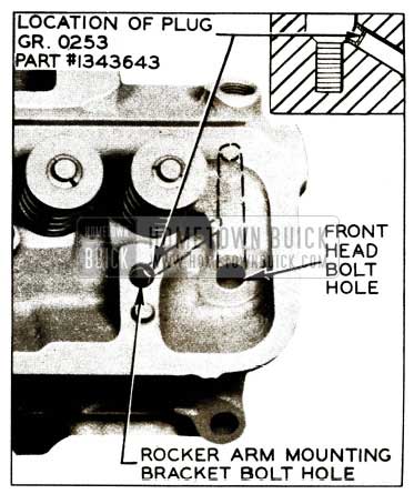
1956 Buick Oil Flow to Valve Train Plug
The installation of this plug in both cylinder heads will reduce oil consumption in those instances where the valve mechanism is receiving an excessive amount of oil.
This plug can be installed by merely removing the rocker arm and shaft assembly from each head and driving plug in oil passage, shown in Fig. 3, using 3/16″ diameter rod as punch.
Flat rate time allowance for installing plug #1343643 in both cylinder heads is .9 hr.
FUEL CONSUMPTION COMPLAINTS
Complaints of high fuel consumption on 1956 cars are being received. Fuel consumption is always high on new cars in cold weather. New engines have high friction. Cold oil in the engines, transmissions and axles also produce high friction in the respective components. In order to start and operate in cold weather until the inlet manifold is warmed up, the choke supplies a rich mixture which reduces miles per gallon of gasoline. All of these factors contribute to high fuel consumption.
The first step in investigating a fuel consumption complaint is to obtain an accurate measurement of gasoline consumption per mile under controlled test conditions. The test should be made with a 1/10 gallon gauge on a reasonably level road, at fixed speeds, without acceleration or deceleration. Test runs should be made in both directions over the same stretch of road to average the effect of grades and wind resistance. Test runs made at 20, 40 and 60 m.p.h. will indicate the approximate efficiency of the low speed, high speed, and power systems of the carburetor and show whether fuel consumption is actually abnormal. If a mileage test indicates that the fuel consumption is above normal, check the following items.
- Fuel Leaks. Check all gasoline pipe connections, fuel pump bowl gasket, gasoline filter gasket and carburetor bow1 gasket.
- Check for low tire pressures (see paragraph 1-1 of the 1955 Shop Manual).
- Check for dragging brakes.
- Ignition Timing – Spark Plugs. Late ignition timing (beyond T.D.C.) causes loss of power and increases fuel consumption. Dirty or worn out spark plugs ate wasteful of fuel.
- Low Grade Gasoline. Use of gasoline of such low grade that ignition timing must be retarded to avoid excessive detonation will give very poor fuel economy.
- Exhaust Manifold Heater Valve. Check for sticking valve or improper setting of thermostat.
- Air Cleaner. Check for dirty or clogged cleaner element and excessive oil in sump.
- Automatic Choke. Check for sticking choke valve and improper setting of thermostat.
- Check for sticking valves.
- Fuel Pump. Check for excessive fuel pump pressure.
- Carburetor Adjustment. Check idle adjustment.
On Carter Carburetor, the metering rod setting may be checked without removing carburetor. For all other corrections to high speed and power systems, the carburetors must be removed and disassembled.
DETONATION
1954, ’55 and ’56 Models
If detonation complaints should become objectionable in your area, the following procedure is to be used:
- The wiring arrangement should be checked to the 1955 Shop Manual to preclude the possibility of preignition.
- Determine whether oil consumption is acceptable. If not, correct.
- Check initial distributor setting. If it is not set at 5° advance, reset to this figure.
- Check to see if centrifugal and vacuum advance of distributor falls within the limits specified in the shop manual. Also, check distributor for dwell angle variation. Dwell angle should not vary more than three degrees total between idle speed and 1500 R .P.M. Follow the manufacturer’s recommendations for calibration and use of the dwell meter. Do not exceed 1500 engine R.P.M. as some dwell meters are not accurate at higher speeds.
- Make sure fuel is of the highest octane that can be conveniently purchased.
- If the above changes don’t seem to bring the octane requirements of the engine within the fuel range the initial spark setting may be retarded to T.D.C. without any noticeable loss in car performance or economy.
- If the previous step does not make the car passable, then carbon blast the chambers in exact accordance with the operating instructions accompanying each Kent-Moore “Headon” carbon blaster.
- The above procedure may be used effectively on 1954, ’55 and ’56 models; however, if after performing the above procedure on either a 1955 or ’56 model and it is not made passable, then contact the zone office for further instructions.
CAMSHAFT THRUST PLATE OMITTED
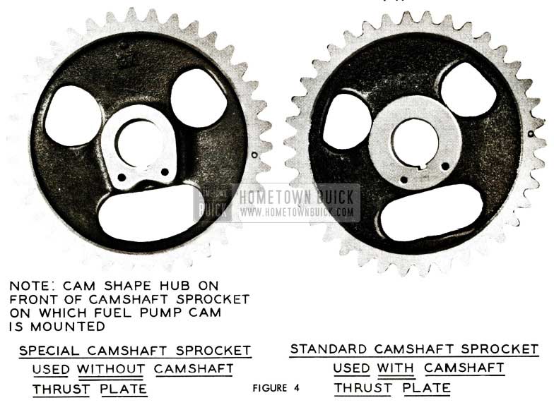
Recently Engineering released a variation in standard production to build 5000 cars in which the camshaft thrust plate and spacer ring were eliminated. It was found that these parts are not necessary since the distributor and oil pump drive produce a rearward thrust on the camshaft at all times; however, in order to eliminate these two parts, a new camshaft sprocket was used and may be seen in Figure 4.
1956 Buick Cylinder Block Plug
If any difficulty is experienced due to this change, install a Standard Type Sprocket with camshaft thrust plate and return the defective parts in the usual way properly tagged with all pertinent information.
CYLINDER BLOCK PLUG
1956 Model
To prevent the possibility of oil leaks occurring at the rear left hand oil gallery in 1956 engines, the welsh plug formerly used is being replaced in 1956 after jobs by a square socket plug 3/8 x 18 thread. This plug fits in the rear end left side of the cylinder block to plug the low pressure oil line, and is available under Gr. 0.253 Part #444782.
OVERHEATING COMPLAINTS
1956
Due to the number of reports received on engine overheating, the following bulletin was developed.
It is felt by Engineering that the 1956 Buick cars are equipped with an adequate cooling system provided the system is clean, the parts are operating satisfactorily and the car is driven correctly. A recommended procedure for determining the cause on cars which are overheating is outlined below:
- Make certain that pressure is held in cooling system by using a known good radiator cap or check cap with an AC pressure cap gauge if available. 1956 non -air conditioned cars should be equipped with a 7 lb. cap and air conditioned cars with a 13 lb. cap. If air temperatures above 110°F are expected, a 13 lb. cap should be installed on a non-air conditioned car to permit higher temperatures before coolant is lost.
- Check tension of fan belts as specified in Shop Manual for non-air conditioner equipped cars, and BPS 2.408 dated June 20, 1956, for air conditioner equipped cars.
- Clean radiator to remove bugs, dirt, etc.
- On air conditioned cars clean condenser to remove bugs, dirt, etc.
- Be sure that the anti-freeze has been drained from the cooling system (radiator and engine block) for summer operation.
- After the above basic checks have been made, road test the car to determine if the cooling system is operating correctly by driving the car 3 to 4 miles to warm it up and then driving at a steady speed of 30 MPH. At an air temperature of 80°F the water temperature gauge hand on either an air conditioned or non-air conditioned car should be at the start of the letter “N”. At an air temperature of ll0° F the hand should be at the start of the red area. For air temperatures between 80° F and ll0°F the location of the hand should be proportional.
- If test 6 indicates the coolant temperature is too hot, clean the inside of the radiator and the water passages of the engine (crankcase and cylinder head). Plugged radiators from core sand, cast iron particles, solder, etc. have been reported. Also, in a few cases it has been found that the cylinder head gaskets were leaking, allowing hot exhaust gases into the cooling system. This can be diagnosed easily by observing air bubbles in the radiator during engine operation.
- The spacing between the condenser and the radiator averages 1 – 1 1/2″. This dimension was determined by actual tests to be the best value for both cooling and air conditioning, so it is undesirable to use other spacing.
- On 1956 air conditioned cars built before July 1, the water temperature gauge hand enters the red area at 205° F to cover boiling of winter alcohol water mixtures. Since water boils at 230° F with a 7 lb. cap and at 243°F with a 13 lb. cap, the car can operate satisfactorily with the hand in the red area. It is only when the hand is at the upper end of the red area and water is lost that it is dangerous to operate the car. Gauges without the red area will be available under Gr. 1.148 Part #1513392 at all warehouses approximately August 1, 1956 for installation on air conditioned cars with the overheating complaint. All air conditioned cars manufactured after July 1 have the red area on the water temperature gauge omitted.
- If the car is being operated in temperatures above 100° it may be necessary to increase the cooling system air flow by installing the six-bladed fan Gr. 1.359 Part #1161825 which is available through Buick Parts Warehouses.
- If the car is going to set in one position for any length of time with the air conditioning operating, the owner should be instructed to put the transmission in Neutral or Park position. Leaving the transmission in Drive or Low and raising the engine speed above idle to maintain flow of cold air from the air conditioned system causes the transmission to pump a tremendous amount of heat into the engine cooling system and will cause overheating.
- If the car is being driven in heavy traffic with most of the time spent stopped or moving very slowly, then the transmission should be put in Low. This will increase the engine speed and hence air flow and water flow rates during portion of time car is moving and assist in maintaining cool water temperatures.
FAN DRIVING PULLEY REPLACEMENT
1954-1955 40 Series
A new crankshaft balancer has been designed for service to be used in place of the three groove cast iron fan driving pulley used on the 1954-1955 series 40 cars equipped with air conditioning and power steering. This new balancer with a one groove and two groove pulley bolted to it will be used for replacements of the original cast iron three groove pulley. The balancer will include a new timing indicator which must be installed replacing the original timing indicator which was used with the cast iron pulley.
Following are the parts involved:
Gr. 0.659- ll65339- Pulley-Fan Driving- 3 Groove
The above part will be replaced by the following when stock on hand is exhausted:
Gr. 0.659 – 1392754- Package-Crankshaft Balancer (Includes Timing Bracket)
Note: When using 1392754 to replace ll65339, it will be necessary to order and use 1 – Gr. 0.659 – 1166162 Pulley (2 Groove) and 1 – Gr. 0.659 – ll68966 Pulley (1 Groove)
It will be necessary to use three (3)5/16-18 x 9/16 Hex. Head Bolts and three (3) 5/16 Lock Washers to attach the pulleys to the balancer. These attaching Parts can be obtained locally.
NEW WATER PUMP COVER
1956
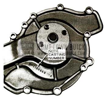
Engineering advises that starting on May 1st, 20,000 engines are to be built using die cast aluminum water pump covers. These covers may be identified by the X -number cast into the cover as shown in Figure 5; also, by the weight and smoothness of casting. If trouble should be encountered with one of these pump covers, the standard 1956 part may be used to replace it.
1956 Buick Water Pump Cover
When dealers are returning these water pump covers to the zone M.R. Room, we ask that it be noted on the AFA and Parts Return Tag that these are field test parts so that the parts may be identified quickly.
OIL GALLERY PLUGS
Engineering advises that they have approved the use of oversize oil gallery plugs in order to avoid scrapping an engine block for plug holes drilled too large during production. Following is a list of the plugs, giving their location, the diameter of the plug holes and the group and part numbers of the standard and oversize plugs to be used in each location. Figure 6 shows the plugs and the group and part numbers in the front of the engine block.
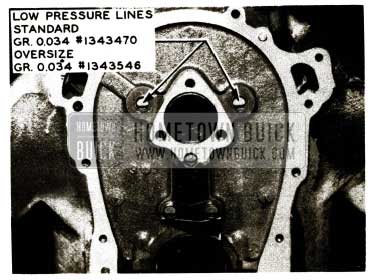
1956 Buick Front Low Pressure Lines
Figure 7 shows the plugs and the group and part numbers in the rear of the engine block.
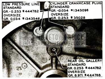
1956 Buick Rear Low Pressure Lines
- Rear Cylinder Crankcase Plug
Standard Size: Hole diameter 1.123 to 1.125 – Plug Gr. 0.034 – Part #1343096
Oversize: Hole diameter 1.213 to 1.215 – Plug Gr. 0.253 – Part #35028
- Front & Right Rear Low Pressure Oil Lines
Standard: Hole diameter .608 to .610 – Plug Gr. 0.034 – Part #1343470
Oversize: Hole diameter .7485 to .7505 – Plug Gr. 0.034 – Part #1343546
NOTE: Right rear low pressure oil line plug is directly ahead of the rear cylinder crankcase plug.
- Rear Oil Gallery
Standard: Hole diameter .5781 for 3/8 – 18 Dryseal Straight pipe thread – Plug Gr. 0.253 – Part #444782
Oversize: Hole diameter .7188 for 1/2 – 14 Dryseal Straight pipe thread – Plug Gr. 8.971 – Part #444788
- Left Rear Low Pressure Oil Line
Standard: Hole diameter .5781 for 3/8 – 18 Dryseal Straight pipe thread – Plug Gr. 0 .253 – Part 444782
Oversize: Hole diameter .7485 to .7505 – Plug Gr. 0.034 – Part #1343546
PISTON DAMAGE BY LOW OCTANE FUEL
1956
We have received a few reports from foreign countries, where fuel octane values are so low that detonation caused engine failures on American tourist cars.
Our Engineering Department advises that the domestic 1956 Buick engine equipped with Dynaflow transmission requires a minimum octane fuel of 96 while the 40 Series equipped with synchromesh transmission requires 89 octane fuel to operate satisfactorily.
Owners contemplating travel outside the U.S. should be cautioned to check on the available fuel before their trip. If satisfactory fuels cannot be assured, the compression ratio should be lowered by installing export pistons and head gasket.
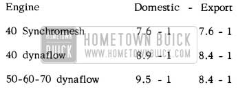
1956 Buick Compression Ratios
The 40 series domestic and export engines with synchromesh transmission and compression ratio of 7.6 – 1 uses the same piston Gr. 0.629 Part # 1392564 and standard .015″ cylinder head gasket Gr. 0.289 Part #1165307. However, the .045″ cylinder head gasket may be installed to lower compression ratio to 7 .35 – 1 if necessary. The 8.4 – 1 compression ratio on all export Dynaflow jobs is obtained by using piston Gr. 0.629 Part #1392566 which is standard on domestic 40 series Dynaflow and .045” cylinder head gasket Gr. 0.289 Part #1343995.
Fuel octane values in general are much lower outside the continental limit of the U.S. Therefore, Buick owners contemplating foreign travel should be cautioned to check on available fuels before beginning their trip. Inquiries pertaining to fuels in foreign countries may be obtained by writing to the Service Department, G. M. Overseas Operations, G.M. Building, Detroit 2, Mich. NOTE: Engine damage caused by detonation as a result of the use of low octane fuels is not considered a defect in material or workmanship; therefore, cannot be considered for warranty adjustment.
OIL ECONOMY INSPECTION PROCEDURE
Following is a reprint of Special Service Letter Dealer No. 183, dated July 20, 1956.
From product reports received to date it is apparent that dealers are needlessly replacing parts in attempting to handle oil consumption complaints. To help eliminate this condition and correct such complaints, it is recommended that the “Oil Inspection Procedure” listed below be followed in the sequence presented.
- Check engine for external oil leaks. This would include the front and rear main bearing seals, oil filter mounting gasket, oil filter bolts, rocker arm cover gaskets, fuel pump gasket, oil pan gasket and plug, oil gallery plugs, timing chain gasket and lifter cover gasket.
- Check viscosity of engine oil. For very hot summer operation where a single viscosity oil is used, it should be SAE 20. If multi-viscosity oil is used, it should be SAE 10W -30. If multi-viscosity oils are used, it is important that they be changed every 2000 to 3000 miles as some types have been found to thin out after higher mileage.
- Check rocker arm shafts to make sure none are upside down – notch should be up.
- Check to see that oil is not squirting out between the bottom of the front rocker arm shaft support and the top face of the cylinder head. Some cylinder heads have been found where the pad that the support sets on has not made sealing contact with the support.
- Check the oil flow down the rocker arms and if this is excessive from all of them then install the Restrictor #1343643.
- If excessive amount of oil is still running down oil rocker arms after installing the restrictor, as outlined in Step 5, then install the new side feed valve rocker arms, one of which is shown in Figure 4 of BPS Bulletin 2.407 dated June 4, 1956. The Parts Department is calling back old type arms and the new type is being shipped to parts warehouses starting July 17, 1956. The following are the part numbers of the new arm listed under Gr. 0.333:
- Right front and left rear – 1169374
- Left front and right rear – 1169375
NOTE: The rocker arm shaft and bracket should be inspected and if worn excessively, replaced.
- If oil consumption is still excessive after the above six steps, then disassemble the engine and check the piston rings and cylinder bores. If compression rings are installed upside down or ring wear is excessive, replace them. If cylinder bores are smooth they should be deglazed. Return removed ring sets through normal channels so they may be analyzed.
VALVE ROCKER ARM CHANGE
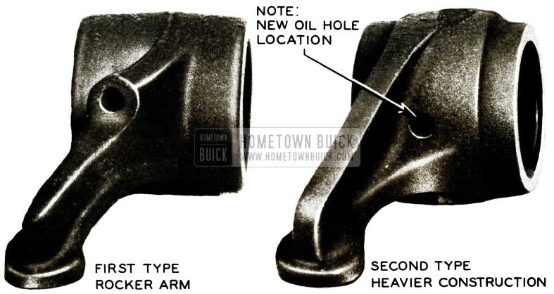
Approximately June 1, 1956 an optional valve rocker arm was used in production and may be identified by the relocation of the oil hole from the top of the rocker arm to the side as shown in Figure 8.
1956 Buick Valve Rocker Arm
These rocker arms are completely interchangeable with the first type. The new rocker arms are available in all warehouses under Gr. 0.333 Part 1169374 and 1169375.
ENGINE OIL IN COOLING SYSTEM
A number of requests have been received for a procedure in diagnosing block and cylinder head leaks when engine oil is found in the cooling system. In most instances, the replacement of one head has corrected this condition.
When oil is found in the cooling system, it must first be determined if it is engine oil or Dynaflow oil. This can be done by using a color dye in one of the units.
After it has been established that the engine is at fault, the following procedure may be used to determine the source of the leak.
- Drain radiator to sufficient level to remove thermostat.
- With the thermostat removed and the water outlet in the water manifold exposed, refill radiator until the water level is 1/2″ below the top of the water manifold.
- Remove the rocker arm cover on either bank of the engine. Also remove the rocker arm assembly from this head.
- Remove the front head bolt from this head and install a reworked head bolt as shown in Fig. 9.
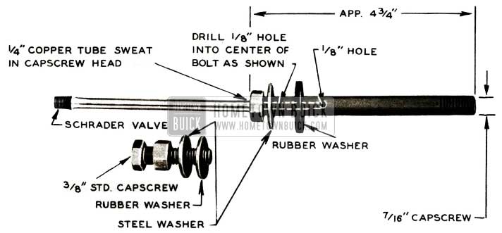
1956 Buick Rubber Washer
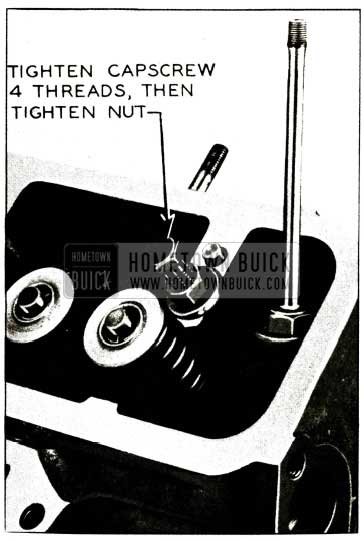
1956 Buick Rubber Washer Cap Screw
CHECKING TIMING MARK
We have received several reports stating that the timing marks were off location on the balancer of 1956 cars.
The quickest and easiest method of checking the timing mark location is to remove the spark plug from #1 cylinder and check the position of U.D.C. in relation to the timing mark on the balancer. This may be done by using an indicator with an extension through the spark plug hole to determine when #1 piston is at U.D.C. At that point the timing mark should be at zero line.
If the timing mark on the balancer is suspected to be off, it may also be checked by removing the balancer and checking the timing mark in relation to the keyway. This can easily be done by drawing a straight line approximately 7” long on a clean sheet of paper; then using a compass, draw a 1 1 /2” diameter circle in center of straight line. See sketch in Figure 11.
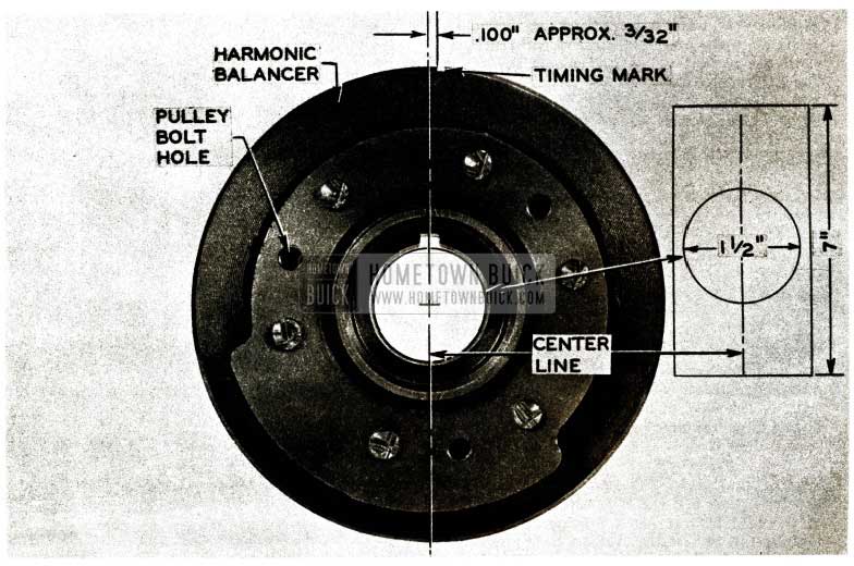
1956 Buick Harmonic Balancer
Place balancer over circle drawn on paper so that centerline passes through center of balancer keyway as shown in Figure 11. The timing mark should be located .100″ (approx. 3/32″) clockwise from centerline at O.D. of balancer. See Figure 11
LOOSE OR CRACKED BALANCER HUB
We have recently encountered several engineering cars which knock loudly at curb idle and/or under light load. Upon investigation it was found that this noise was due to harmonic balancers which were loose axially and caused by either of the following:
- The flat washer bottoms on the end of the front of the crankshaft instead of the balancer hub. See Figure 12, View A.
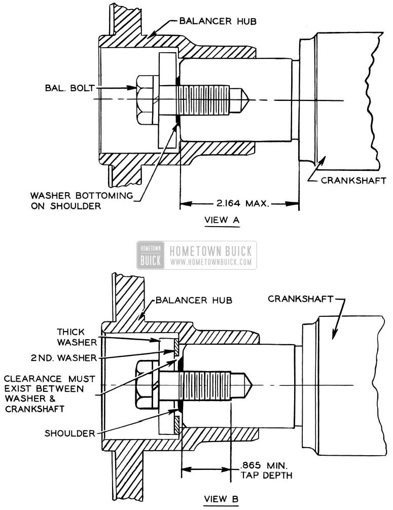
1956 Buick Harmonic Balancer Hub
In both cases (1 and 2), the balancer bolt can be tightened to the specified torque (55-65 ft. lbs.) but the balancer assembly will be lose axially. These conditions will not only cause an objectionable noise but will also crack the balancer hub at keyway section.
The first condition may occur if small shoulder is left on the front of the crankshaft or if the balancer hub is machined too short. Either of these possibilities may be eliminated by installing a second washer of sufficient thickness having the same O.D. as that of washer now used, and large enough I.D. to clear the shoulder on end of shaft and provide sufficient clearance between end of crankshaft and thick washer. (See View B, Figure 12). As an alternate method for correcting this condition, the shoulder on end of crankshaft may be filed or chiseled off.
The second condition occurs when the bolt hole is not tapped deep enough in the end of the crankshaft. This may be eliminated by tapping the hole to the proper depth (View B, Figure 12) with a standard N.F. 1/2 – 20 tap.
Steps have been taken in Production to eliminate this condition in the future.
USE OF 60 ENGINE WITH SYNCHROMESH TRANSMISSION
We have received several inquiries concerning the use of a 1956 Series 60 Engine in a 1956 Series 40 with Synchromesh Transmission. The standard production Series 60 Dynaflow Engine can be installed in a Series 40 with Synchromesh Transmission by changing several parts. The production Series 60 Engine Gr. 0.000 Part 1392333 for cars equipped with single exhaust and Gr. 0 .000 Part 1392330 for cars equipped with dual exhausts, may be ordered from your warehouse and installed by making the following changes:
Remove the following part from the Series 60 Engine as received:
1 – Dynaflow Flywheel
Order the following parts separately and install them on the Series 60 Engine:
1 – Gr. 0.649 Part 1161771 Bearing and Adapter Clutch Gear Pilot
2 – Gr. 3.402 Part 1552426 Air Cleaner and Silencer
3 – Gr. 8 .154 Part 1340106 Bolt-Air Cleaner and Silencer to Support
4 – Gr. 3.403 Part 1167128 Stud-Air Cleaner and Silencer Hold Down
5 – Gr. 8.920 Part 148305 Wing Nut (2)
6 – Gr. 3.430 Part 1162451 Rod-Throttle Operating
Transfer the following parts from the Series 40 Engine to the Series 60 Engine:
1 – Upper Flywheel Housing, Bolts and Dowels
2 – Lower Flywheel Housing and Bolts
3 – Flywheel and Clutch Assy., Bolts and Dowels
4 – Fan Driving Pulleys, fan hub, fan spacer, fan and fan belt
5 – Fan Driven Pulleys
6 – Generator and Brace
7 – Ignition Coil, Distributor Cap and Wires
FAN SHROUD VIBRATION
(1956 Models 50-60 MPH)
The fan shroud at speeds between 50-60 has been found to produce a resonant noise period which may sometimes be confused with high speed rumble caused by the torque ball. BPS 2.412 described the torque ball change whereby the inner ring of bonded rubber was removed from the torque ball to provide more positive alignment at this location. Dealer Product Reports received to date in most cases state that the vibration at the critical speeds mentioned above is eliminated by installing the new torque ball and inner retainer package Gr. 5.564 Part 1392949. However, a few reports stated that no improvement was observed after installation of the new torque ball. It is felt that in these few instances the fan shroud may be causing the resonant noise period. It is suggested, therefore, that when a complaint of this nature is encountered, the procedure listed below be followed to first determine whether or not the fan shroud is at fault.
- Connect a tachometer to engine. Start engine with transmission lever in park position and slowly increase engine speed to approximately 2200 to 2400 RPM where objectionable noise is definite.
- With the hood raised, have another man place his hands on outer edge of fan shroud to dampen shroud vibration. Extreme caution must be exercised when doing this to prevent hands from being caught in engine fan.
- If noise as heard inside the car is greatly reduced or eliminated when second man’s hands are placed on outer edge of fan shroud, stop engine and remove shroud.
- Obtain approximately 12 feet of 1/4″ x 1/2″ aluminum channel of .042″ thickness. Two (2) 6 feet lengths of Reynolds “Do-It- Yourself” Aluminum Item #16 will be satisfactory.
- Cut aluminum channel strips into eight (8) 18” lengths so that they may be installed on shroud as shown in Figure 13.
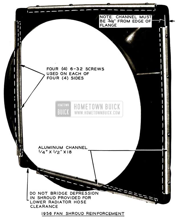
1956 Buick Fan Shroud
Note: Channel used on inner side of shroud has the “U” section extending away from shroud with flat section resting against it. It is suggested that on each of the four sides the outer and inner aluminum channel be held in position with “C” clamps for drilling. Note: Aluminum channel must be 3/4″ in from edge of fan shroud to clear shroud mounting bolt holes.
Installation of eight pieces of aluminum channel will strengthen the fan shroud and effectively minimize, if not completely eliminate, fan shroud noise.
Flat rate time for installing 8 pieces of channel on fan shroud as described above is .6 hr. Total time allowed for R&R fan shroud and installing channel is 1.4 hrs. (If equipped with power steering, add .1 hr. to D&C fan belt).
Leave A Comment
You must be logged in to post a comment.