SECTION 13-B 1957 BUICK DOORS AND CENTER PILLAR (SERIES 40-60)
13-6 1957 BUICK FRONT AND REAR DOORS (SERIES 40-60)
Several new changes have been incorporated in the design of the front and rear door hardware parts. Some of these parts, such as window frames on the 41 and 48 bodies and the 1957 Buick door inner panel water deflector, are new in design and require new service methods. The side roof rail weatherstrip on the 43 and 63 bodies and the front door weatherstrip on the 48 bodies are also of a new design, requiring new service methods.
The 1957 Buick door section is divided into the following parts: Service operations which are the same or similar for both front and rear doors. Service operations for the front door. Service operations for the rear door.
Removal and Installation of 1957 Buick Front and Rear Door Inside Handles
- Depress 1957 Buick door trim assembly at handle. Insert spring removing tool between handle and bearing plate and remove handle retaining spring; then, remove handle and bearing plate.
- To install inside handle, first install retaining spring to handle; then, position bearing plate and handle on regulator spindle and push handle until spring is engaged.
NOTE: Install handle at same angle as handle on opposite door. Window or ventilator should be in closed position when checking angle of handle.
Removal and Installation of 1957 Buick Front and Rear Door Belt Finishing Moldings
- Remove 1957 Buick door inside locking rod knob.
- Remove finishing screw from both ends of molding and remove molding from 1957 Buick door.
- To install, position inside locking rod through molding and position finishing molding on door; then, reverse removal procedure.
Removal and Installation of Front and Rear Arm Rests
- On underside of arm rest, remove two (2) screws securing arm rest to arm rest support on door inner panel and remove arm rest.
NOTE: On 63 bodies, also detach clip securing forward end of arm rest to 1957 Buick door. See figure 13-24.
1957 Buick Trim Pad Clip
- To install, reverse removal procedure.
Removal and Installation of 1957 Buick Front Door Trim
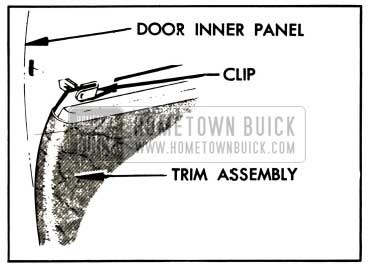
The 1957 Buick door trim assembly is attached to the door inner panel with individual spring-type retaining clips. To prevent damaging the 1957 Buick door trim assembly during removal, a door trim assembly removal tool should be used. See figure 13-25.
1957 Buick Door Trim Pad Tool
- Remove door belt finishing molding and inside handles.
- Remove 1957 Buick door arm rest.
NOTE: On 66C, 63 and 66R bodies, after removing 1957 Buick door arm rest remove two (2) screws securing door arm rest hanger plate and remove hanger plate.
- Remove one (1) screw at both lower corners of trim assembly.
- With clean rubber mallet tap trim assembly along front and rear edges to free trim assembly retaining clips in slots.
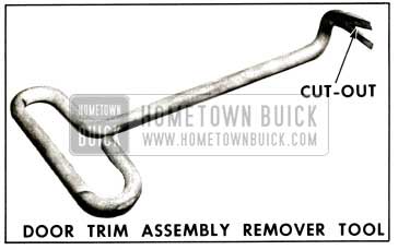
- Insert 1957 Buick door trim assembly remover tool between door trim assembly and water deflector until handle of tool contacts door trim foundation.
NOTE: Exercise care so as not to disturb water deflector. Then position tool to engage cut-out in tool with edge of clip and pry clip and trim assembly away from door inner panel.
CAUTION: The 1957 Buick door trim assembly remover tool must be engaged with clip to prevent damage to trim assembly as there is no metal strip along the edge of the trim assembly.
- On 1957 Buick doors equipped with electrically operated window regulators, disconnect terminal block from switch assembly by carefully pulling block to disengage it from switch terminal post.
- Lift trim assembly upward to disengage trim assembly from retaining tabs and long metal retainer along lower edge of door inner panel.
- To install, reverse removal procedure. On doors equipped with electrically-operated window regulators, check operation of switch after connecting terminal block.
NOTE: Make sure that tension springs are reinstalled over window regulator and door handle spindles and that trim assembly is engaged with tabs and long metal retainer.
Removal and Installation of 1957 Buick Rear Door Trim
The 1957 Buick door trim assembly is secured to the door inner panel by a nailing strip along the front and rear edge of the trim assembly, by a trim retainer along the bottom of the door, and by two (2) retaining tabs on the door inner panel.
- Remove 1957 Buick door inside handle (s), bearing plate (s), and door belt finishing molding.
- Remove arm rest.
NOTE: On rear doors of 63 bodies after removing door arm rest remove two (2) screws securing arm rest hanger plate and remove plate.
- Remove screws from lower corners of trim assembly.
- With a clean mallet, tap trim assembly along front and rear edges to free trim assembly nails in retainer slots.
- Place a suitable flat-bladed tool between water deflector and door trim assembly and carefully loosen front and rear edges of door trim assembly from door inner panel.
- NOTE: Exercise extreme care so as not to disturb water deflector.
- Lift trim assembly upward to disengage it from retaining tabs and metal retainer which is located along lower edge of door inner panel.
- On 1957 Buick doors equipped with electrically powered window regulators, carefully pull terminal block from switch terminals, then remove trim assembly.
- To install reverse removal procedure. Make certain tension springs are reinstalled over door handle spindles where required and that trim assembly is engaged with retainer tabs and metal retainer before tapping in nail strips at front and rear edges of trim assembly.
NOTE: If during removal of trim assembly any retaining nails are broken off, they can be replaced with door trim assembly nailing strip replacement tabs which are available as a service part.
Removal and Installation of 1957 Buick Front and Rear Door Window Control Switches
- Remove 1957 Buick door belt finishing molding and door inside handles.
- Loosen upper portion of trim assembly sufficiently to disconnect terminal block from switch assembly by pulling block from switch terminals.
- Carefully push switch assembly from trim assembly to release switch from retainer.
NOTE: In some instances it may be necessary to pry open retainer tabs to release switch.
- To remove switch from escutcheon, depress clips at sides of switch with pointed tool inserted through holes in sides of escutcheon.
- To install control switch, reverse removal procedure.
NOTE: The feed stud of the master control switch should be towards the rear of the body when installed in trim assembly. Check operation of switch before completing installation of parts.
Removal of 1957 Buick Door Water Deflectors
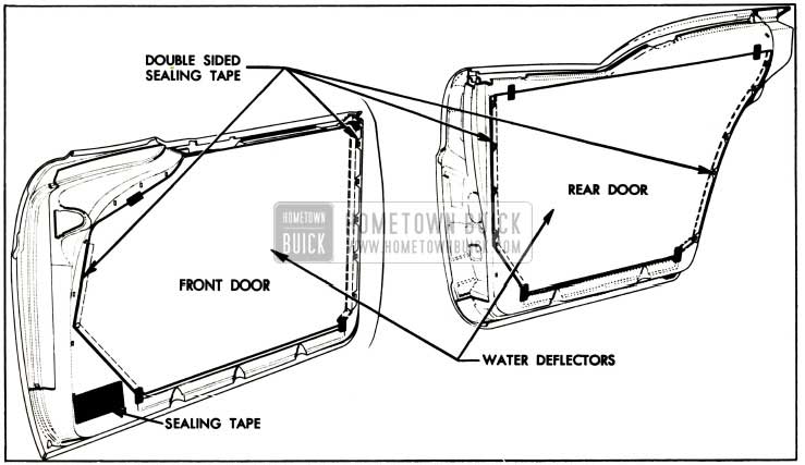
A 1957 Buick door water deflector consisting of a waterproof paper secured to the door inner panel by an elastic double sided sealing tape is provided on the doors of all styles. The deflector which covers the complete door inner panel fits into a slot along the bottom of the door inner panel and deflects water into the bottom of the door where it can drain out the door bottom drain holes. Whenever any work is performed on a door where the water deflector has been disturbed the deflector must be properly sealed and attached to the inner panel as specified in the following procedures.
- Remove 1957 Buick door belt finishing molding door trim assembly. Remove trim assembly retainer tabs and door arm rest hanger plates where present.
- Carefully detach water deflector from door inner panel. Use caution that dirt or foreign matter does not get on exposed surface of tape and destroy adhesive qualities of tape.
Installation of 1957 Buick Door Water Deflectors
- Prior to installing water deflector, make certain surfaces of inner panel or water deflector contacted by sealing tape is free of any foreign material to insure a satisfactory seal.
NOTE: If adhesive quality of sealing tape has been damaged, cover affected area with an additional strip of tape or weatherstrip cement to insure a proper weatherseal.
- On 1957 Buick front doors apply waterproof body tape over the lower hinge access hole. On rear doors apply sealer over trim assembly lower front corner retaining slot. (See Fig. 12-26.)
1957 Buick Door Water Deflectors
Removal and Installation of 1957 Buick Door Lock Strikers
- With a pencil scribe position of striker on body pillar.
- Remove three door lock striker attaching screws and remove striker and adjusting plates from pillar.
- To install, place striker and adjusting plates within scribe marks on pillar and tighten screws.
IMPORTANT: Whenever a 1957 Buick door has been removed and installed, or realigned, the door SHOULD NOT be closed completely until a visual check is made to determine if the lock extension will engage in the striker notch. Where required, door lock striker emergency spacers should be installed so that door can be closed and an accurate check made to determine emergency spacer requirements.
1957 Buick Door Lock Striker Adjustments
- To adjust striker “up” or “down” or “in” or “out” loosen striker plate screws and shift striker and adjusting plates as required, then tighten screws.
- Dimensional specifications for use of 1957 Buick door lock striker emergency spacers.
(a) Door should be properly aligned before checking door spacer requirements.
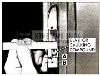
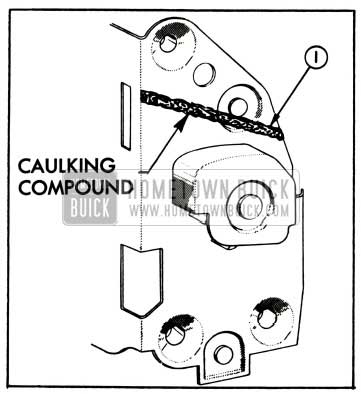
(b) To determine if 1957 Buick door lock striker emergency spacers are required, apply modeling clay or body caulking compound in the door lock striker notch where the lock extension engages and then close the door to form a measurable impression in the clay or caulking compound, as shown in Fig. 13-27.
1957 Buick Striker Spacing
When dimension “A” from inside face of striker teeth to center of lock extension is less than 3/16″, install emergency spacers and proper length striker attaching screws as directed below.
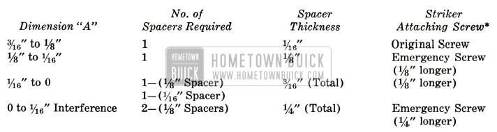
1957 Buick Door Lock Strikers Specifications
NOTE: Dimension “B” from center of lock extension to inside face of striker should never be less than 1/16″.
*Zinc or cadmium plated flat head cross recess screw with countersunk washer.
1957 Buick Door and Side Roof Rail Weatherstrips
The 1957 Buick door and side roof rail weatherstrips are constructed of foam rubber encased in an outer skin of hard rubber. This outer casing must not be broken if the weatherstrip is to perform its proper function since the foam rubber is water absorbent. Any small breaks or factures that occur in the outer casing should be repaired by applying black weatherstrip cement to the affected area. If large breaks occur the weatherstrip should be replaced.
Removal of 1957 Buick Front Door Weatherstrip (Models 41-48)
The newly designed front door weatherstrip is a continuous loop-type mechanically-retained weatherstrip with external clips formed from a wire insert within the weatherstrip. The weatherstrip is installed from the outer side of the door and then secured to the door by snapping the weatherstrip clips into holes around the perimeter of the 1957 Buick door. In addition the weatherstrip is cemented to the door at the cove area.
- Remove the 1957 Buick door belt finishing molding. Remove five screws securing front door ventilator garnish molding assembly and remove assembly.
- With a flat-bladed tool carefully break cement bond along cove area of door.
- Carefully position tip of mechanically retained weatherstrip inserting tool, or any other suitable tool, under weatherstrip at each clip location and snap clip out of hole. Then work weatherstrip over door hemming flange and remove from body.
Installation of 1957 Buick Front Door Weatherstrips
- Remove 1957 Buick door trim assembly and inner panel water deflector.
- Check weatherstrip clips for proper contour and reform if necessary using clip reforming tool J-5984. See figure 13-28.
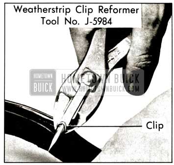
1957 Buick Weatherstrip Clip Reforming Tool
1957 Buick Door Weatherstrips
NOTE: When installing ventilator garnish molding, slide front edge of molding over four (4) door weatherstrip retaining clips; then install screws securing molding.
Removal and Installation of 1957 Buick Rear Door Weatherstrips (Model 41)
The 1957 Buick rear door weatherstrips are a one-piece mechanically-retained type with external clips formed from a wire insert extending through the length of the weatherstrip. The weather-strips are secured to the door by snapping the weatherstrip clips into holes around the perimeter of the door. The ends of the weatherstrips are cemented together to form a “butt” joint at the bottom of the door. In addition the weatherstrip is cemented at the upper rear corner of the door at the belt line.
- Use a flat-bladed tool and carefully break cement bond at “butt” joint on bottom of door and break cement bond at upper rear corner of door at belt line.
- Use a mechanically-retained weatherstrip inserting tool, or other suitable tool, and carefully position tip of tool under weatherstrip at each clip location and snap clip out of hole.
- To install weatherstrips remove 1957 Buick door trim assembly and inner panel water deflector.
- Check weatherstrip clips for proper contour and reform if necessary using clip reforming tool No. J-5984. (See Figure 13-28.)
- Clean off old cement from surface of door to provide a clean cementing surface for weatherstrip installation.
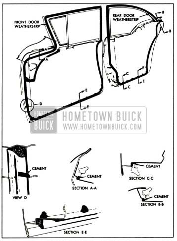
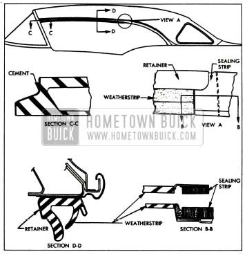
- Apply an approved weatherstrip cement to weatherstrip attaching surface along upper rear corner of door as indicated in Section “B-B” in Figure 13-29 and to corresponding surface of weatherstrip.
- Position color mark on weatherstrip between fourth and fifth holes from hinge pillar corner of door upper facing, and position formed bend of weatherstrip at upper rear corner of door at belt line.
- Starting at formed portion of weatherstrip install weatherstrip-retaining clips around perimeter of 1957 Buick door. To install clips into clip holes, place “V-shaped” tip of weatherstrip inserting tool on loop of clip; then push clip into hole until it snaps into position.
NOTE: Do not use excessive force or strike tool when pushing clips into holes as it may distort shape of clip, resulting in improper weatherstrip retention.
- Trim off ends of weatherstrip if necessary and form “butt” joint between two (2) center holes on bottom of 1957 Buick door.
NOTE: Service replacement weatherstrips may be longer than required to assure a satisfactory “butt’ joint. Do not cut weatherstrip to form “butt” joint until all clips are installed into holes around the 1957 Buick door.
- Apply weatherstrip cement to ends of weatherstrip and to bottom of door approximately 2 1/2 inches on both sides of “butt” joint as shown in section “C-C” Figure 13-29. Form “butt” joint with ends evenly matched to provide a continuous seal.
- Working through large access hole apply medium-bodied sealer over and around weatherstrip attaching clips along bottom of door and to lower clip on each pillar (See Section “E-E”, Figure 13-29.)
- Install all previously removed parts.
Removal and Installation of 1957 Buick Front and Rear Door Weatherstrips – Riviera and Convertible Bodies
The front and rear door weatherstrips are one-piece weatherstrips secured to the door by a combination of integral tabs and clips. In addition, on front doors, the weatherstrip is cemented along the “cove” area and at the upper rear corner of the door. On rear doors the weatherstrip is cemented at the upper rear corner of the door. An additional weatherseal is obtained on the rear doors by the use of a rear door hinge pillar sealing strip assembly. This sealing strip is located adjacent to the end of the door weatherstrip and is secured in place by one (1) screw.
1957 Buick Door Weatherstrip
- Remove 1957 Buick door belt finishing molding.
- On front doors remove screws securing weatherstrip to ventilator frame and screw (s) securing lock pillar end of weatherstrip. On rear doors remove screws securing ends of weatherstrip to hinge pillar and lock pillar. (See figure 13-31.)
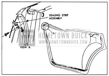
1957 Buick Rear Door Hinge Pillar Sealing Strip
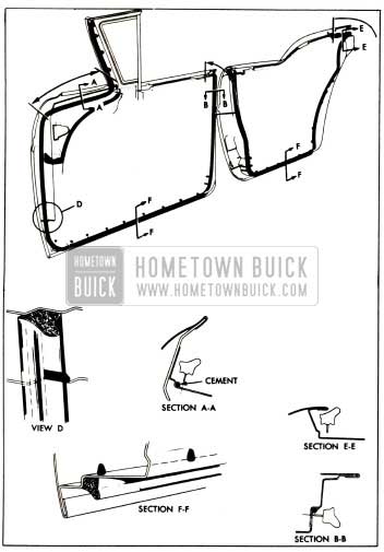
- On front door, apply cement from point three (3) inches above “cove” area completely around “cove” area as indicated in section “A-A”, Figure 13-30. Apply cement in corner of rabbit on door beginning at lock pillar end of weatherstrip and extending downward to a point just below the second clip as shown in section “B-B”. Apply cement to joint of door inner panel and door hinge pillar as indicated in View “D”, Figure 13-30, to prevent water from entering under weatherstrip. Clean off excess cement.
- On rear doors apply cement in corner of rabbit beginning at lock pillar end of weatherstrip and extending downward to a point between fourth and fifth attaching holes as shown in section “E-E”.
NOTE: Do not use excessive force or strike tool when pushing clips into holes as it may distort shape of clip, resulting in improper weatherstrip retention.
- Install weatherstrip tab attaching screws at ends of weatherstrip.
- Working through access hole apply medium-bodied sealer over and around weatherstrip attaching clips as indicated in section “F-F”, Figure 13-30.
- Clean off all excess cement and install door inner panel water deflector door trim assembly and belt finishing molding.
Removal and Installation of Front Door Hinge Pillar Auxiliary Weatherstrip
- With a flat-bladed tool carefully remove three (3) snap-on fasteners securing weatherstrip, then break cement bond and remove weatherstrip from door pillar. (See Figure 13-29 or 13-30.)
- To install clean off old cement from area of hinge pillar contacted by weatherstrip.
- Apply an approved weatherstrip cement to the surface of the hinge pillar contacted by the weatherstrip and to the weatherstrip attaching surface.
- Install weatherstrip to hinge pillar, aligning snap-on clip in weatherstrip with holes in hinge pillar.
- Install snap-on clips. Firmly press or roll entire length of weatherstrip to hinge pillar to assure a complete cement bond.
- Clean off any excess cement.
1957 Buick Front and Rear Door Bottom Drain Hole Sealing Strips
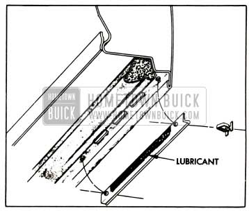
Two (2) door bottom drain hole sealing strips are located on the bottom of each door. Each sealing strip is attached to the door inner panel by a snap-on fastener at each end of the strip. To prevent the strip from adhering to the door inner panel and blocking the drain holes, apply a sparing amount of silicone rubber lubricant on the center section of the weatherstrip as indicated in Figure 13-32.
1957 Buick Front and Rear Door Bottom Drain Hole Sealing Strip
1957 Buick Front Body Hinge Pillar Auxiliary Upper Weatherstrip – Rivieras and Convertibles
The front body hinge pillar auxiliary weatherstrip is a one-piece mechanically- retained weatherstrip secured to the body hinge pillar by four (4) clips. Either of two (2) types of clips may be used:
- A loop-type clip may be formed from a wire insert extending through the entire length of the weatherstrip. This type of clip requires the use of the mechanically-retained weatherstrip inserting tool to remove and install the weatherstrip.
- Individual rectangular clips, equally spaced along the weatherstrip may be used. This type of clip requires the use of long nose pliers, or other suitable tool, to remove and install the weatherstrip.
NOTE: Before removing the weatherstrip check the weatherstrip to determine which type of clip is used. If a wire insert can be felt within the weatherstrip the mechanically-retained inserting tool must be used.
- To remove and install weatherstrip with loop-type clips:
- Carefully position tip of a mechanically retained weatherstrip inserting tool, or any other suitable tool, under weatherstrip at each clip location and snap clip out of hole. Then remove weatherstrip.
- Position weatherstrip to hinge pillar and install clips into holes with mechanically retained weatherstrip inserting tool. To install clips in holes place “V-shaped” tip of tool on loop and push clip into hole.
NOTE: Do not use excessive force or strike tool when pushing clips into holes as it may distort shape of clips and cause improper weatherstrip retention.
- To remove and install weatherstrip with rectangular-type clips:
- Position long nose pliers or other suitable tool under weatherstrip at each clip location and squeeze clip to disengage barbed part of clip and remove clip from hole.
- Position weatherstrip to hinge pillar and apply thumb pressure at each clip location to install clip.
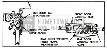
Removal and Installation of 1957 Buick Side Roof Rail Weatherstrip (Models 43-63)
This newly designed side roof rail weatherstrip is a one-piece mechanically-retained type with external clips formed from a wire insert extending through the length of the weatherstrip. In addition to the clips the weatherstrip is secured by a side roof rail weatherstrip retainer which is attached to the side roof rail by screws.
IMPORTANT: At the center of the weatherstrip, a section (approximately ten (10) inches long) is provided with a reinforced outer skin to prevent excessive wear from the rear door window upper frame during closing and opening of the 1957 Buick door. This reinforced section of the weatherstrip should be correctly located to properly perform its function. See Fig. 13-93.
- With a flat-bladed tool, carefully break cement bond between front end of weatherstrip and body windshield pillar.
- Disengage weatherstrip from outer flange of retainer. Then carefully position tip of mechanically-retained weatherstrip inserting tool, or any other suitable tool, under weatherstrip at each clip location and snap clip out of hole.
- Before installing, check weatherstrip clips for proper contour and reform if necessary using weatherstrip reforming tool J-5984.
- Position weatherstrip to retainer at side roof rail so that front end “butts” against body windshield pillar and reinforced section (approximately ten (10) inches long) is over front edge of the rear door window upper frame. Install weatherstrip clips into clip hopes with mechanically-retained weatherstrip inserting tool. To install clips into holes, place “V-shaped” tip of tool on loop of clip, then push clip into hole until it snaps into position.
NOTE: Do not use excessive force or strike tool when pushing clips into holes as it may distort shape of clips resulting in improper weatherstrip retention.
- Apply weatherstrip cement to front end of weatherstrip and cement it to body windshield pillar.
- Engage weatherstrip in both inner and outer flanges of retainer along entire length of retainer.
- With 1957 Buick doors and windows closed, front and rear door window upper frames should make an even continuous contact with the side roof rail weatherstrip. If necessary, adjust ventilator and /or front and rear door windows to obtain proper weatherstrip contact.
- Lubricate side roof rail weatherstrip as outlined in “LUBRICATION” section.
Side Roof Rail Weatherstrip Adjustments (Models 43-63)
The attaching holes in the side roof rail weatherstrip retainer are elongated allowing “in” and “out” adjustment of the side roof rail weatherstrip; however, the amount of adjustment is small and is not intended to correct for improper ventilator or door window alignment. The retainer attaching screws are located under the weatherstrip necessitating removal of the weatherstrip to make an adjustment.
IMPORTANT: Before attempting to adjust the side roof rail weatherstrip, first check that the ventilator and front and rear door windows are properly aligned and, where necessary, adjust for proper alignment as directed under “ADJUSTMENTS” in the Ventilator, Front Door Window and Rear Door Window service procedures.
- To adjust side roof rail weatherstrip “in” or “out” first determine and mark retainer at area or areas to be adjusted; then remove side roof rail weatherstrip.
- Loosen weatherstrip retainer attaching screws slightly in area to be adjusted; then place wooden block or suitable tool against the inner or outer flange of the retainer and tap tool lightly to properly position retainer.
- Tighten retainer attaching screws and reinstall weatherstrip.
Removal and Installation of 1957 Buick Side Roof Rail Weatherstrip Retainer (Models 43-63)
The side roof rail weatherstrip retainer is a channel-type molding secured to the side roof rail by twelve (12) screws. The retainer may be adjusted “in” or “out”; however, the amount of adjustment is small and is not intended to correct for improper ventilator or door window alignment. It is important that the ventilator and the front and rear door windows are checked and, if necessary, aligned for proper contact with the side roof rail weatherstrip prior to installation of the retainer and weatherstrip.
- Remove side roof rail weatherstrip from retainer.
- Remove screws securing side roof rail weatherstrip retainer to side roof rail and remove retainer.
NOTE: Exercise care during removal so as not to bend molding as they may affect proper weatherseal after installation.
- Before installing remove sealer from side roof rail and retainer to insure a clean sealing surface.
- Apply sealer to top of retainer just outboard of attaching holes along entire length of retainer. (See Fig. 13-33.)
1957 Buick Side Roof Rail Weatherstrip
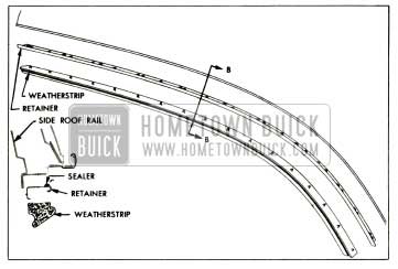
Removal and Installation of Side Roof Rail Weatherstrip (Models 43-63)
The newly designed side roof rail weatherstrip is secured to the side roof rail by a channel-type retainer. Holes are provided in the weatherstrip and retainer to be adjusted without removing the weatherstrip.
NOTE: Due to accessibility of weatherstrip retainer attaching screws, the weatherstrip may be removed in either of two ways.
- Weatherstrip may be removed directly from body.
- Weatherstrip and retainer assembly may first be removed and then weatherstrip removed from retainer.
The following procedure covers removal of the weatherstrip directly from the body.
- With a flat-bladed tool, carefully break cement bond between front end of weatherstrip and windshield pillar and cement bond between rear end of weatherstrip and side roof rail quarter sealing strip located within retainer.
- With a flat-bladed tool, carefully disengage outboard lip of weatherstrip from retainer and remove weatherstrip.
- Before installing clean off cementing surface on windshield pillar to provide a smooth surface.
- Apply an approved weatherstrip cement to both ends of weatherstrip and install weatherstrip to retainer. To facilitate installation, engage outboard edge of weatherstrip to retainer just prior to engaging inboard edge.
NOTE: Make certain each lip of weatherstrip at rear end of weatherstrip forms a “butt” joint with each lip of sealing strip as shown in section “B-B” Figure 13-34.
1957 Buick Side Roof Rail Weatherstrips
- If installing a new weatherstrip, make certain holes in weatherstrip are aligned with retainer attaching screws. Carefully trim front end of weatherstrip flush against body windshield pillar and rear end flush against sealing strip to insure proper weatherseal and neat appearance.
1957 Buick Side Roof Rail Weatherstrip Adjustments (Models 46R-66R)
The attaching holes in the side roof rail weatherstrip retainer are elongated allowing “in” and “out” adjustment of the side roof rail weatherstrip, however, the amount of adjustment is small and is not intended to correct for improper ventilator or door window alignment. The side roof rail weatherstrip need not be removed to adjust the retainer.
IMPORTANT: Before attempting to adjust the side roof rail weatherstrip first check that the ventilator and door window are properly aligned and, where necessary, adjust for proper alignment as directed under “ADJUSTMENTS” in the Ventilator, and Door Window service procedures.
- To adjust side roof rail weatherstrip “in” or “out” first determine and mark retainer at area, or areas, to be adjusted.
- Loosen retainer attaching screws slightly in areas to be adjusted; then, adjust retainer in or out as required.
NOTE: Make adjustments along sufficient length of the retainer to insure a continuous seal.
- Tighten retainer attaching screws.
Removal and Installation of Side Roof Rail Weatherstrip Retainers (Models 46R-66R)
- Remove side roof rail weatherstrip from retainer.
NOTE: Due to accessibility of retainer attaching screws, the weatherstrip and retainer may first be removed from body and then weatherstrip removed from retainer.
- Remove side roof rail rear quarter sealing strip front attaching screw.
- Remove screws securing retainer to side roof rail; then carefully detach rear end of retainer from sealing strip and remove retainer.
- Before installing clean off sealing surfaces of retainer and side roof rail to insure a smooth surface.
- Apply a continuous 3/16″ bead of caulking compound along top of retainer just outboard of attaching holes and along front of retainer.
- Position rear end of retainer over forward end of sealing strip, then position front end of retainer against body windshield pillar and install retainer.
NOTE: Seal forward end of sealing strip to side roof rail to insure a proper weatherseal.
- Install side roof rail weatherstrip.
- With 1957 Buick doors and windows closed, the door window upper frame and ventilator frame should make an even, continuous contact with the side roof rail weatherstrip. If necessary adjust ventilator and/or door window to obtain proper weatherstrip contact.
13-7 1957 BUICK FRONT DOORS (SERIES 40-60)
The 1957 Buick front door hinges are the swing-out type with an integral check and hold open, similar to past models. At both the upper and lower front door hinges one of the hinge to front body hinge pillar attaching bolts is installed from the front of the front body pillar necessitating detachment or removal of chassis parts to gain access to the bolts for removal of the hinges from the body. However, these bolts have a hexagon end and can be loosened from inside the hinge box thereby facilitating adjustment of the door hinges at the body pillar without removal of chassis parts. The 41 and 48 doors have a removable door window frame. All 1957 Buick doors are equipped with a waterproof door inner panel water deflector which is sealed to door inner panel. The bottom edge of the deflector fits into a slot along the bottom of the door inner panel thereby deflecting any water into the bottom of the door where it can drain out the door bottom drain holes. Door lock levers are provided with redesigned spring clips which will facilitate easier detachment of the connecting rods.
Removal and Installation of 1957 Buick Front Door Assembly
- Place suitable protective covering over front fender at door opening to protect finish.
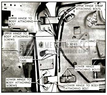
- Remove 1957 Buick door trim assembly. Detach edge of door inner panel water deflector sufficiently to gain access to upper hinge strap bolts. Fig. 13-36.
1957 Buick Front Door Hinges
- Remove door inner panel water deflector.
- Remove screws securing electrical conduit to door hinge pillar, then bend down conduit tabs and remove conduit from wire harness, Fig. 13-36.
- Disconnect harness connector from studs on regulator motor and detach wire harness clips or harness from clips as required to remove harness from between door panels through opening in door hinge pillar.
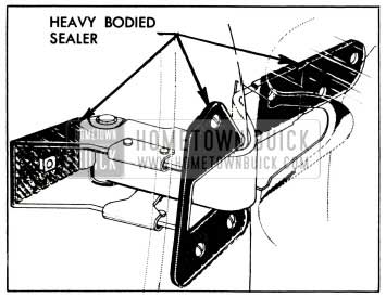
NOTE: As an anti-squeak precaution, before installation of door, coat attaching surface of hinge with heavy-bodied sealer, as indicated in Fig. 13-37.
1957 Buick Front Door Hinge Sealing
1957 Buick Front Door Adjustments
Door adjustments are provided through the use of floating cage nuts and anchor plates in the door and adjacent hinge pillar. The 1957 Buick front doors may be adjusted fore or aft at the 1957 Buick door hinge straps, and in or out at the front body hinge pillar; up or down adjustments may be made at both the door hinge strap and front body hinge pillar.
IMPORTANT: After performing any door adjustments the door lock extension-to-striker engagement should be checked and if necessary adjusted, as described under “DOOR LOCK STRIKER ADJUSTMENTS.” In addition the front door ventilator and window should be checked for proper alignment with the side roof rail mechanical sealing strip or the side roof rail weatherstrip and adjusted where required.
- To adjust the front doors fore or aft and / or up and down proceed as follows:
- Remove 1957 Buick door trim assembly. Remove tape covering lower hinge access hole. Detach upper front edge of door inner panel water deflector sufficiently to gain access to upper hinge strap bolts, Fig. 13-36.
- Remove door lock striker from body pillar to allow the door to hang freely on the hinges.
- Scribe location of hinge straps on door. (d) Loosen hinge strap bolts, Fig. 13-36 and shift door to desired position, then retighten bolts.
NOTE: Additional up or down adjustment may be obtained at the front body hinge pillar. (e) Apply waterproof body tape over lower hinge access hole. Reseal upper front edge of inner panel water deflector, then install previously removed door trim and inside hardware.
- To adjust the front doors in or out and /or up and down at the body front hinge pillar, proceed as follows:
- Scribe location of hinge on body front hinge pillar.
- Inside hinge box loosen (turn clockwise) hinge attaching bolt installed from front of body hinge pillar.
IMPORTANT: Use a six point single (hexagon) type socket.
- Loosen hinge attaching bolts at face of hinge pillar. Shift door to desired position; tighten bolts at face of pillar then tighten (turn counterclockwise) bolt inside hinge boxes to 40-45 ft. lbs.
1957 Buick Front Door Ventilator and Ventilator Regulator
The front door ventilator, ventilator frame and ventilator regulator are new in design and method of attachment. The ventilator, ventilator frame and ventilator regulator may be removed from the door as a complete unit; however, the service methods described in this section cover procedures for the separate assemblies.
Removal and Installation of Front Door Ventilator Garnish Molding (Models 41-48)
- Lower door window and remove door belt finishing molding.
- Remove three (3) ventilator garnish molding attaching screws at front of molding and one (1) screw at top and bottom of molding.
- Carefully remove garnish molding from under door weatherstrip and remove from door.
- To install front door ventilator garnish molding, reverse removal procedure.
Removal and Installation of Front Door Ventilator (Models 41-48)
- Lower door window. Remove door trim assembly, ventilator garnish molding and inner panel water deflector.
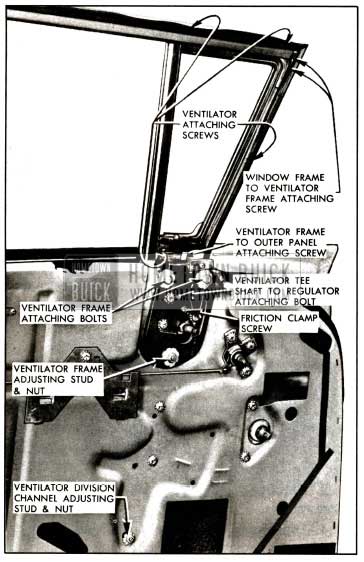
- Remove ventilator tee shaft to regulator shaft attaching screw and ventilator regulator attaching screws, Figure 13-38.
1957 Buick Front Door Ventilator
Remove ventilator regulator from door through front access hole.
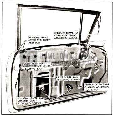
Removal and Installation of 1957 Buick Front Door Ventilator Frame (Models 41-48)
- Remove front door ventilator assembly as described under “FRONT DOOR VENTILATOR ASSEMBLY- REMOVAL AND INSTALLATION.”
- Detach 1957 Buick door weatherstrip from ventilator area.
- Remove window frame to ventilator frame attaching screws at upper front of ventilator.
- Remove ventilator frame to outer panel attaching screw, ventilator frame adjusting stud and nut and ventilator frame attaching bolts, Figure 13-38; then remove ventilator frame from door.
- To install 1957 Buick front door ventilator frame, reverse removal procedure. Adjust ventilator assembly as outlined under “FRONT DOOR VENTILATOR ADJUSTMENTS.”
Removal and Installation of Front Door Ventilator Assembly-Rivieras and Convertibles
- Lower door window. Remove door trim assembly and inner panel water deflector.
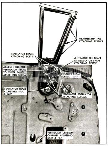
- Remove weatherstrip tab attaching screws at front of ventilator frame, as indicated in Figure 13-39.
1957 Buick Front Door Ventilator View
NOTE: Ventilator regulator may be removed from ventilator as a bench operation by loosening the ventilator tee shaft to regulator shaft attaching screw and removing the regulator attaching screws, Figure 13-39.
- To install front door ventilator assembly, reverse removal procedure. Adjust ventilator assembly as outlined under “FRONT DOOR VENTILATOR ADJUSTMENTS.”
1957 Buick Front Door Ventilator Adjustments
The 1957 Buick front door ventilator assembly can be adjusted up or down and in or out at the top for alignment in the door opening and proper weatherstrip contact in the ventilator area. The lower portion of the ventilator division channel can be adjusted in or out and fore or aft for alignment with the 1957 Buick door window glass. On the Riviera and Convertible bodies the ventilator assembly can be adjusted fore or aft for alignment with the body windshield pillar.
To adjust the ventilator assembly proceed as follows:
- Remove 1957 Buick door trim assembly and inner panel water deflector.
- Remove ventilator frame to outer panel attaching screw at location indicated in Figure 13-39 and 13-38.
- Loosen ventilator division channel adjusting stud nut and ventilator frame adjusting stud nut.
- Loosen ventilator frame attaching bolts.
- (a) To adjust upper portion of ventilator in or out, turn ventilator frame adjusting stud and ventilator division channel adjusting stud in or out, as required, then tighten stud nuts and all attaching bolts.
- To adjust ventilator assembly up or down, and on Riviera and Convertible bodies to adjust ventilator fore or aft, position entire ventilator assembly, as required, then tighten all attaching bolts and stud nuts.
- Install ventilator frame to outer panel attaching screw at location indicated in Figure 13-39 and 13-38. Seal water deflector to door inner panel and install door trim and inside hardware.
Removal and Installation of 1957 Buick Front Door Ventilator Regulator
- Raise 1957 Buick door window. Remove door trim assembly and inner panel water deflector.
- Loosen ventilator tee shaft to regulator shaft attaching screw.
- Remove ventilator regulator attaching screws.
- Disengage regulator from ventilator tee shaft and remove from door through forward access hole.
- To install front door ventilator regulator, reverse removal procedure.
Ventilator Regulator Adjustments
- Excessive “play” (flutter) of the ventilator at the pivot shaft when the ventilator is in the open position can be corrected by tightening the ventilator tee shaft to regulator shaft screw, Figure 13-38 and 13-39.
NOTE: Screw should be tightened carefully to avoid stripping threads in regulator spiral gear shaft.
- The operating effort required to open or close the ventilator can be slightly increased or decreased by adjusting the friction clamp screw.
Removal and Installation of 1957 Buick Front Door Window Assembly (Models 41-48)
- Lower 1957 Buick door window. Remove door trim assembly and inner panel water deflector.
- Remove front door ventilator as described under “FRONT DOOR VENTILATOR – REMOVAL AND INSTALLATION.”
- Remove window lower sash channel cam attaching screws indicated in Figure 13-40; raise window and remove from between door panels.
1957 Buick Front Door Window-Models 41-48
CAUTION: On 1957 Buick doors with electrically operated window DO NOT OPERATE REGULATOR MOTOR after the window assembly is disengaged from the regulator. Operation of the motor with the load removed may damage the unit and make it inoperative.
- To install window assembly, reverse removal procedure.
1957 Buick Front Door Window Adjustments (Models 41-48)
The 1957 Buick door inner panel cam and the lower end of the ventilator division channel may be adjusted to relieve a binding door glass caused by misalignment of the window with the glass run channels.
- To correct a condition where the glass is “cocked” in the glass run channels, loosen the inner panel cam rear attaching screw, Figure 13-40; adjust rear of cam up or down as required and retighten screw.
- To adjust the lower portion of the ventilator division channel for alignment with the window, loosen ventilator division channel adjusting stud nut. Turn adjusting stud in or out or position lower end of channel fore or aft as required, then retighten adjusting stud nut.
Removal and Installation of 1957 Buick Front Door Window Frame (Models 41-48)
- Remove 1957 Buick front door ventilator and window assemblies.
- Detach door weatherstrip from window and ventilator area.
- Remove window frame lower attaching bolt at location shown in Figure 13-40.
NOTE: On 48 bodies remove rubber access hole plug to gain access to attaching bolt. - At upper front of ventilator remove two (2) screws, indicated in Figure 13-40 securing window frame to ventilator frame.
- Remove window frame attaching screw and bolt at belt line.
- Carefully detach window frame from ventilator frame; rotate window frame outward sufficiently to allow attaching tab on frame to clear between door panels; then lift frame upward and remove from door.
- To install front door window frame, reverse removal procedure.
NOTE: If installing new window frame transfer glass run channel to new frame.
The lower end of the front door window frame may be adjusted in or out to provide proper weatherstrip contact and /or window frame alignment at top rear of the 1957 Buick door. To adjust window frame loosen window frame attaching screw and bolt at belt line. Loosen lower attaching bolt and adjust lower end of window frame as required.
1957 Buick Door Window Glass Run Channels (Models 41-48)
The front door window frames on 41 and 48 bodies are equipped with vertical glass run channels and upper glass run channels. The channels are designed to snap into the window frame and can be removed by squeezing the sides of the channel together and pulling, or carefully prying, the channel from the window frame.
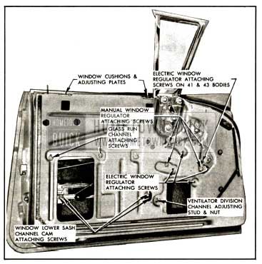
Removal and Installation of 1957 Buick Front Door Window-Rivieras and Convertibles
- Lower 1957 Buick door window. Remove door trim assembly and inner panel water deflector.
- Remove window cushion adjusting plates, Figure 13-41.
1957 Buick Front Door Window-Rivieras and Convertibles
CAUTION: On 1957 Buick doors with electrically operated windows DO NOT OPERATE REGULATOR MOTOR after the window assembly is disengaged from the regulator. Operation of the motor with the load removed may damage the unit and make it inoperative.
- To install window assembly, reverse removal procedure.
Front Door Window Adjustments – Rivieras and Convertibles
To adjust the 1957 Buick door window glass for proper contact with the side roof rail weatherstrip or to relieve a binding door glass caused by misalignment of the glass with the glass run channels, proceed as follows:
- To correct a condition where the glass is “cocked” in the glass run channels, loosen the inner panel cam rear attaching screw, Figure 13-41; adjust rear of cam up or down as required and retighten screw.
- To adjust the upper front position of the window in or out for proper contact with the side roof rail weatherstrip, adjust top of ventilator assembly in or out as described under “FRONT DOOR VENTILATOR ADJUSTMENTS.”
- To adjust the lower portion of the ventilator division channel for alignment with the window, loosen ventilator division channel adjusting stud nut, Figure 13-41. Turn adjusting stud in or out or position lower end of channel fore or aft, as required; then, retighten adjusting stud nut.
- To adjust rear of window upper frame in or out for proper contact with the side roof rail weatherstrip, or to adjust rear of window in or out at belt line, loosen glass run channel attaching screws. Position channel as required and retighten screws.
- To adjust limit of “up” travel of the window for proper contact with the side roof rail weatherstrip, adjust window cushions.
Removal and Installation of 1957 Buick Front Door Window Glass Run Channel – Rivieras and Convertibles
- Raise 1957 Buick door window. Remove door trim assembly and detach rear portion of inner panel water deflector.
- Remove glass run channel attaching screws, Figure 13-41.
- Working through rear access hole, lower glass run channel from behind window frame extension and remove from door.
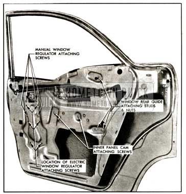
Removal and Installation of 1957 Buick Front Door Window Regulator Assembly (Manual and Electric)
- Lower 1957 Buick door window. Remove door trim assembly and inner panel water deflector.
- Remove window lower sash channel cam attaching screws, Figure 13-41, raise window and prop in up position.
CAUTION: On 1957 Buick doors with electrically operated windows DO NOT OPERATE REGULATOR after the window assembly is disengaged from the regulator. Operation of the motor with the load removed may damage the unit or make it inoperative.
- On 1957 Buick doors with electrically operated windows, disconnect wiring harness connector from regulator motor through forward access hole.
- Remove ventilator division channel lower adjusting stud and nut.
- Remove inner panel cam attaching screws. Detach cam from regulator arm and remove from door.
- Remove window regulator attaching screws. On 41 and 43 bodies equipped with electrically operated window regulator remove regulator attaching screw indicated in Figure13-41. Carefully work regulator assembly through r ear access hole and remove from 1957 Buick door.
NOTE: Instructions for removing the motor from the regulator assembly are outlined under “REMOVAL AND INSTALLATION OF FRONT DOOR WINDOW REGULATOR ELECTRIC MOTOR ASSEMBLY.”
Removal and Installation of 1957 Buick Front Door Window Regulator Electric Motor Assembly
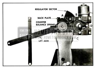
- Remove electric window regulator assembly from door as described under “FRONT DOOR WINDOW REGULATOR ASSEMBLY-REMOVAL AND INSTALLATION” and clamp securely in vise, Figure 13-42.
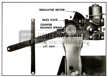
1957 Buick Electric Window Regulator
NOTE: The position of the regulator clamped in the vise will vary with the type of regulator and position of the lift arm.
CAUTION: BE SURE TO PERFORM STEPS 2 AND 3 BEFORE ATTEMPTING TO REMOVE THE MOTOR FROM THE REGULATOR. The regulator lift arm, which is under tension from the counter-balance spring can cause serious injury if the motor assembly is removed without locking the sector in position.
- Drill 1/4″ hole through backplate and sector at location indicated by “A,” “B” or “C” in Figure 13-42, depending on position of lift arm.
NOTE: Do not drill into motor housing, part of which is indicated by the dotted lines. In addition, locate hole not less than 3/4″ away from edge of backplate or sector.
- Insert 3/16″ bolt through holes in backplate and sector and install nut to bolt. (Do not tighten nut.)
- Remove the three (3) attaching bolts “D” and remove motor assembly from regulator, Figure 13-42.
NOTE: Clean off steel chips from the regulator sector and motor pinion gear after drilling operation.
- To install, reverse removal procedure. The regulator lift arms may be moved up or down manually so that motor pinion gear will mesh with teeth on regulator sector.
NOTE: Be sure to remove temporary nut and bolt from regulator after motor is installed.
1957 Buick Front Door Locking Mechanisms
All 1957 Buick door locks are the rotary bolt-type lock with the interlock feature. With the interlock feature it is very important that the lock extension engage properly in the striker notch and that, where necessary, striker emergency spacers of the proper thickness are used to obtain proper engagement. On 43 & 63 bodies an adjusting nut is provided at the lower end of the door outside handle connecting rod which can be adjusted to provide proper action of the outside handle push button. An adjusting screw on the end of the outside handle push button shaft on the 41 body is provided for the same purpose.
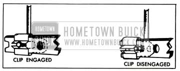
1957 Buick Door Lock Spring Clip
A redesigned spring clip is used on the 1957 Buick door lock levers to secure the connecting rods to the lock levers. A slot in the spring clip provides easier disengagement of the clip thereby facilitating easier detachment of the lock connecting rods from the lock.
To disengage spring clips, use a screw driver or other suitable tool to slide clip out of engagement. Figure 13-43 shows a door lock spring clip engaged and disengaged.
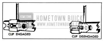
1957 Buick Door Lock Spring Clip
Removal and Installation of 1957 Buick Door Lock (Model48)
- Raise 1957 Buick door window. Remove door trim assembly and inner panel water deflector.
- Remove window frame bolt access hole plug from lock pillar. See figure 13-44.
1957 Buick Door Lock Removal-Models 41-48
Then remove window frame lower attaching bolt through access hole.
1957 Buick Front Door Lock Sealing
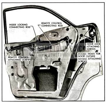
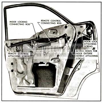
Removal Installation of 1957 Buick Front Door Lock (Model 41)
- Raise 1957 Buick door window. Remove door trim assembly and inner panel water deflector.
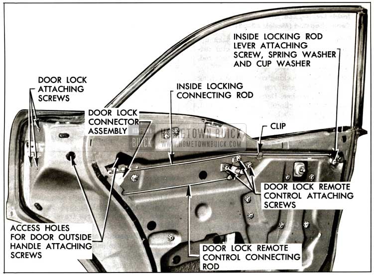
- Through large access hole disengage spring clips and detach the remote control connecting rod, the inside locking connector-to lock rod, and lock cylinder connecting rod from lock.
- Remove door lock attaching screws and remove door lock from door through large access hole.
- To install front door lock, reverse removal procedure. Prior to installation of front door lock apply a ribbon of medium-bodied sealer (approximately 1/4″ in diameter) across face of lock frame, as indicated in Fig. 13-45.
Adjust nut on end of outside handle push button shaft to provide between 1/32″ and 1/8″ free travel of the push button; then tighten jamb nut.
Removal and Installation of Front Door Inside Locking Rod to Lock Connector Assembly (Model 41)
- Raise 1957 Buick door window. Remove door trim assembly and inner panel water deflector.
- Through large access hole disengage spring clips and detach inside locking rod and inside locking connector-to-lock rod from connector assembly.
- Remove three (3) screws securing connector assembly to door lock pillar and remove connector assembly from door.
- To install connector assembly, reverse removal procedure.
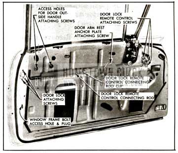
Removal and Installation of 1957 Buick Front Door Lock-Rivieras and Convertibles
- Raise 1957 Buick door windows, remove door trim assembly and inner panel water deflector.
- On two door Rivieras and Convertibles remove door window assembly.
- Remove glass run channel attaching screws on face of lock pillar, Figure 13-46 and remove channel from door.
1957 Buick Front Door Lock-Rivieras and Convertibles
On four door Rivieras lower glass run channel from behind window frame extension to remove from door.
- Remove door arm rest anchor plate attaching screws, see Figure 13-44, and remove anchor plates where present.
- Remove door lock remote control attaching screws, and remove remote control.
- Detach remote control connecting rod from clip, then detach rod from door lock and remove from door.
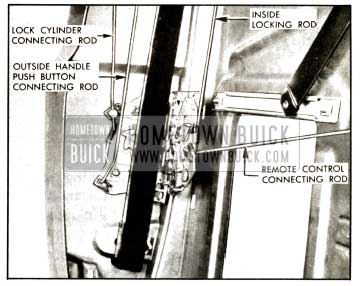
1957 Buick Front Door Lock-Models 43-63
- On 43 and 63 bodies disengage spring clip and detach outside handle push button connecting rod adjusting nut from lock, Figure 13-47.
- Disengage spring clips and detach remote control connecting rod and inside locking rod from lock, Figure 13-47.
Prior to installation of front door lock on all styles except 43 and 63, apply a ribbon of medium-bodied sealer (approximately 1/4, inch in diameter) across face of lock frame, as indicated in Figure 13-45.
On the 43 and 63 adjust nut on end of outside handle push button connecting rod to provide between 1/32″ and 1/8″ free travel of the push button.
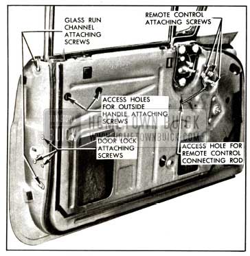
Removal and Installation of 1957 Buick Front Door Lock Remote Control and Connecting Rod
- Raise door window. Remove door trim assembly and inner panel water deflector.
- On 43 and 63 bodies disengage spring clip and detach remote control connecting rod from lock, Figure 13-47.
- Remove remote control attaching screws, Figure 13-44 and 13-46 and remove remote control.
- On all except 43, 63 and 41 bodies detach remote control connecting rod from clip on inner panel, disengage rod from door lock and remove from 1957 Buick door.
- On 43, 63 and 41 bodies remove remote control connecting rod from door through access hole, shown in Figure 13-46.
- To install door lock remote control, reverse removal procedure. Check operation of door lock before installing inner panel water deflector.
Remote Control Adjustments
- Remove door trim assembly. Detach upper front portion of door inner panel water deflector sufficiently to gain access to remote control attaching screws.
- Loosen remote control attaching screws, Fig. 13-44. Adjust remote control in a rearward direction to just take out linkage clearances. Tighten screws to specified torque.
- Check operation of door lock before resealing water deflector.
Removal and Installation of Front Door Outside Handle Assembly
- Raise door window. Remove 1957 Buick door trim assembly and inner panel water deflector.
- Through large access hole disengage spring clip and detach lock cylinder connecting rod from 1957 Buick door lock.
- On 43 and 63 bodies disengage spring clip and detach outside handle push button connecting rod adjusting nut from lock.
- Through access holes for outside handle attaching screws, Figure 13-44 and Figure 13-46 remove handle attaching screws. Remove outside handle and with attached connecting rod or rods from door. Remove connecting rod or rods with anti-rattle clips from handle assembly.
- To install 1957 Buick door outside handle assembly, reverse removal procedure making sure gaskets are installed between the handle and door outer panel at front and rear attaching points.
NOTE: On 43 and 63 bodies adjust nut on end of outside handle push button connecting rod to provide between 1/32″ and 1/8″ free travel of the push button.
On 41 bodies adjust nut on end of outside handle push button shaft to provide between 1/32″ and 1/8″ free travel of the push button; then tighten jamb nut.
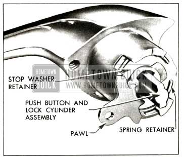
Disassembly and Assembly of 1957 Buick Front Door Outside Handle Assembly
The 1957 Buick front door outside handle assembly includes the lock cylinder assembly. This necessitates the removal and disassembly of the outside handle assembly to remove the lock cylinder assembly.
- Remove door outside handle assembly as previously described.
- While maintaining pressure to hold component parts within handle, use a suitable tool and remove spring retainer; then remove parts as shown in appropriate figure.
- Figure 13-48 for 43 and 63 bodies.
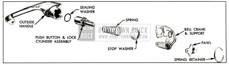
1957 Buick Front Door Outside Handle Assembly-43-63 Bodies
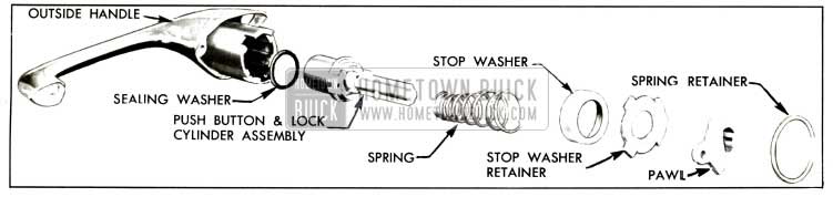
1957 Buick Front Door Outside Handle Assembly-Two-Door Bodies
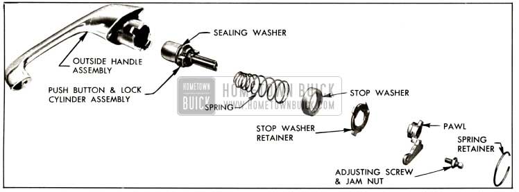
1957 Buick Front Door Outside Handle Assembly-41 Bodies
NOTE: To disengage pawl from stop washer retainer or bell crank lever rotate pawl to cutouts and remove.
- To assemble door outside handle first engage pawl to bell crank lever or stop washer retainer; then reverse removal procedure making certain open end of spring retainer is located at nipple on adjacent part. See appropriate figure.
- Figure 13-51 for 43 and 63 bodies.
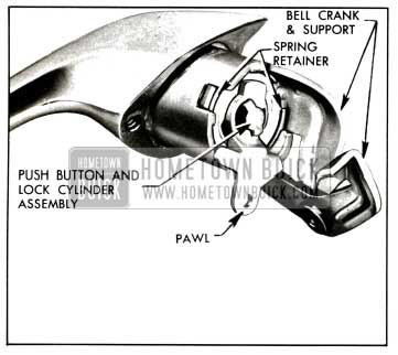
1957 Buick Front Door Outside Handle Assembly-Four-Door Bodies
1957 Buick Front Door Outside Handle Assembly-Two-Door Models
Disassembly and Assembly of 1957 Buick Front Door Lock Cylinder
The 1957 Buick front door lock cylinder is located in the door lock outside handle push button assembly. To remove the lock cylinder, it is necessary to remove the push button assembly from the handle.
- Remove and disassemble door outside handle as previously described.
- With a suitable tool remove detent spring from lock cylinder.
- Carefully bend out tabs securing lock cylinder cap and remove lock cylinder sleeve and lock cylinder. See Fig. 13-53.
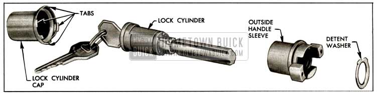
1957 Buick Front Door Lock Cylinder
NOTE: When installing detent spring make certain raised portions of spring rest in depressions in sleeve.
13-8 1957 BUICK REAR DOORS (SERIES 40-60)
The 1957 Buick rear doors are attached to the center pillar by two (2) butt-type hinges. The lower hinge, which is new in design, has an integral door check and hold-open and is secured to an anchor plate on the door and center pillar by three (3) screws at each location. The upper hinge is secured to an anchor plate on the door hinge pillar by three (3) screws and to an upper hinge support on the center pillar by three (3) bolts.
1957 Buick Rear Door Assembly Removal
Either of the following two (2) methods can be used to remove the door from the body. (1) The 1957 Buick door can be removed from the hinge straps. (2) The door and hinge straps can be removed from the center pillar.
- Operate window to down position.
- Clean off excess sealer around each hinge strap and scribe location of hinge straps on door hinge pillar or center pillar depending on method of removal being used.
- On 1957 Buick doors with electrically-operated windows proceed as follows:
- Remove two (2) screws securing electrical conduit to door hinge pillar, bend down tabs securing harness to conduit and remove conduit.
- Remove necessary hardware to remove door trim assembly and remove assembly.
- Detach water deflector sufficiently to gain entrance to large access hole.
- Through access hole detach wire harness from clips and disconnect harness wires from window regulator motor leads. Then remove wire harness from door.
- Depending on method of removal, properly support door and remove three (3) upper and lower hinge to door pillar attaching screws at door hinge pillar or three (3) upper and lower hinge to center pillar attaching screws, Fig. 13-54.
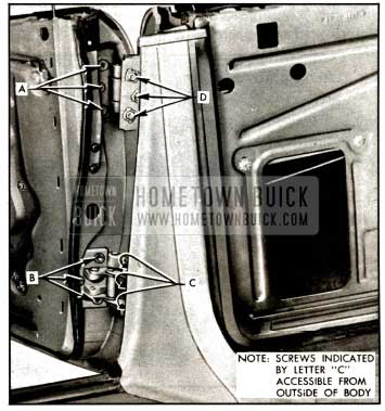
1957 Buick Rear Door Hinges
NOTE: Screws securing lower hinge strap to center pillar are accessible from outside of body when door is in full “open” position.
- With aid of a helper remove door from body opening.
1957 Buick Rear Door Assembly Installation
- With scraper and mineral spirits, clean off old sealing compound at hinge areas.
NOTE: This operation should be performed carefully to avoid possibility of soiling adjacent trim material.
- Apply a coat of heavy-bodied sealer to attaching surfaces of hinge straps or to corresponding surfaces of door or body, as indicated in Figure 13-55.
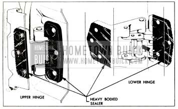
1957 Buick Sealing Rear Door Hinges
It is important to obtain complete coverage with sealer to obtain proper sealing and anti-squeak effects. In addition, lubricate frictional surface of 1957 Buick door hold open assist assembly as outlined in Lubrication Section.
- Install wire harness to attaching clips inside of door and connect ends to motor leads. Check operation of window.
- Install conduit to hinge pillar and secure wire harness in conduit with retaining tabs.
- Reseal water deflector to inner panel as specified under “Door Inner Panel Water Deflector”.
- Install door trim assembly and previously removed door hardware.
1957 Buick Rear Door Adjustments
The 1957 Buick rear door hinge adjustments differ from those performed on previous models. “In and out” and “up and down” adjustments are provided at the door hinge pillar. “Fore and aft” adjustments are provided at the center pillar.
When checking the door for alignment, remove the door lock striker from the body pillar to allow the door to hang free on its hinges.
NOTE: After performing any adjustments the rear door window should be checked for proper alignment with the side roof rail weatherstrip and adjusted where required. In addition the door lock extension-to-striker engagement should be checked and adjusted if necessary.
- For “in and out” or “up and down” adjustments loosen hinge to door pillar attaching screws, Fig. 13-54; adjust door as required and tighten screws.
NOTE: When performing “in and out” adjustments, adjust one (1) hinge at a time so that the “up and down” adjustment is maintained.
- To adjust the door “fore and aft” loosen hinge to center pillar attaching screws, Fig. 13-54, adjust door as required and tighten screws and bolts.
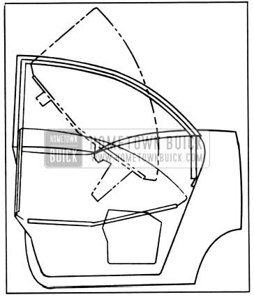
Removal and Installation of 1957 Buick Rear Door Window Assembly (Model 41)
- Lower rear door window assembly. Remove door trim assembly and inner panel water deflector.
- Remove window rear guide upper and lower attaching studs and nuts, Fig. 13-59, then disengage guide from shoes on window lower sash channel and remove from door by pulling guide upward through cut-out in top of door inner panel.
1957 Buick Rear Door Window Frame-Model 41
1957 Buick Rear Door Window-Model 41
CAUTION: On 1957 Buick doors with electrically operated window regulators DO NOT OPERATE REGULATOR MOTOR after the window assembly is disengaged from the regulator. Operation of the motor with the load removed may damage the unit.
- Carefully lift window upward and inboard to clear window frame as indicated in Fig. 13-57 and remove window assembly from 1957 Buick door.
1957 Buick Rear Door Window Installation-Model 41
1957 Buick Rear Door Window Adjustments (Model 41)
To adjust the window fore or aft or to relieve a binding condition caused by window being misaligned with the glass run channels, proceed as follows:
- Remove 1957 Buick rear door trim assembly and inner panel water deflector.
- To adjust window assembly in or out for alignment with the glass run channels, loosen rear guide stud nuts and turn adjusting studs, Fig. 13-58, in or out, as required. Tighten adjusting stud nuts.
1957 Buick Rear Door Window Adjustments-Model 41
Removal and Installation of 1957 Buick Rear Door Window Re.ar Guide (Model41)
- Lower rear door window assembly. Remove door trim assembly and inner panel water deflector.
- Remove window rear guide upper and lower attaching studs and nuts, Fig. 13-58; then disengage guide from shoes on window lower sash channel and remove from door by pulling guide upward through cut-out in top of 1957 Buick door inner panel.
- To install window rear guide, reverse removal procedure. Prior to installation of the guide, lubricate channel portion of guide with Lubriplate along entire length of channel. Check operation of window assembly and, where required, adjust window as described under “REAR DOOR WINDOW ADJUSTMENTS”.
Removal and Installation of 1957 Buick Rear Door Window Regulator (Manual and Electric (Model 41)
- Lower 1957 Buick rear door window assembly. Remove door trim assembly and inner panel water deflector.
- On 1957 Buick doors with electrically operated window regulators, disconnect wire harness connector from regulator motor.
CAUTION: DO NOT OPERATE REGULATOR MOTOR after- the window assembly is disengaged from the regulator or after the regulator is removed from the door. Operation of the motor with the load removed may damage the unit.
- Remove window lower sash channel cam attaching screws, Fig. 13-59, then lift window assembly and prop in up position.
- Remove inner panel cam attaching screws, Fig. 13-58, then detach cam from regulator arms and remove from 1957 Buick door.
- Remove window regulator attaching screws, Fig. 13-58, and remove regulator assembly from door through large access hole.
- To remove electric motor from regulator assembly see “REAR DOOR WINDOW REGULATOR ELECTRIC MOTOR ASSEMBLY – REMOVAL AND INSTALLATION.”
- To install window regulator assembly, reverse removal procedure.
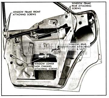
Removal and Installation of 1957 Buick Rear Door Window Frame Assembly (Model 41)
- Remove 1957 Buick rear door window. Remove glass run outer sealing strip front and rear attaching screws.
- Detach door weatherstrip from window frame. Remove door window frame front and rear attaching screws, Fig. 13-59.
- Carefully lift window frame upward, rotate rear of frame outward and remove from door.
- To install door window frame assembly, reverse removal procedure.
NOTE: If installing new window frame transfer glass run channels to new frame.
1957 Buick Rear Door Window Frame Adjustments
The upper portion of the rear door window frame can be adjusted in or out to provide proper weatherstrip contact along the upper portion of the door opening. To adjust the window frame proceed as follows:
- Remove 1957 Buick door belt finishing molding. Loosen window frame front and rear attaching screws, Fig. 13-59.
- Position lower ends of window frame in or out to provide proper weatherstrip contact along the upper portion of the door opening.
- Tighten all window frame attaching screws.
1957 Buick Rear Door Window Glass Run Channels (Model41)
The 1957 Buick rear door window frame on the 41 body is equipped with a vertical glass run channel and an upper glass run channel. The channels are designed to snap in the window frame and can be removed by squeezing the sides of the channel together and pulling or carefully prying the channel from the window frame.
Removal and Installation of 1957 Buick Rear Door Window Assembly (Manual and Electric) (Models 43-63)
- Raise 1957 Buick door window assembly. Remove door trim assembly and inner panel water deflector.
- Through access hole, shown in Fig. 13-60, loosen female wedge plate attaching screw.
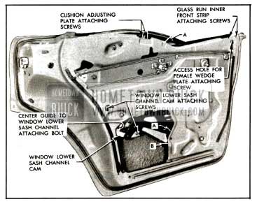
1957 Buick Rear Door Window Removal-Models 43-63
Lower window; then through large access hole remove wedge plate from front of window lower sash channel.
CAUTION: On 1957 Buick doors with electrically operated window regulators DO NOT OPERATE REGULATOR MOTOR after the window assembly is disengaged from the regulator. Operation of the motor with the load removed may damage the unit.
- Using a screw driver at location “A”, Fig. 13-60, disengage spring clip on end of regulator balance arm. At the same time insert another screw driver, at location “B”, and disengage regulator balance arm from pin on window lower sash channel.
- Lift window assembly with attached center guide straight up between door panels so that the center guide comes out through depression in inner panel, at location “A”, Fig. 13-60.
- To install 1957 Buick rear door window assembly, reverse removal procedure. Prior to installing the window assembly apply Lubriplate or its equivalent to the frictional surfaces of the front, center and rear guides.
When engaging center guide over center guide shoe make sure anti-rattle clip is also engaged in channel of guide.
After installation of window assembly and before installing inner panel water deflector, check operation of window. Check for proper window frame contact with the side roof rail weatherstrip and window front frame weatherstrip contact with the front door window. Where necessary adjust window, as described under “REAR DOOR WINDOW ADJUSTMENTS-43-63 BODIES.”
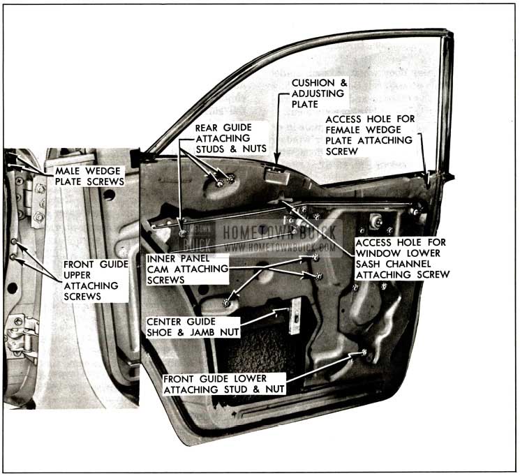
1957 Buick Rear Door Window Adjustments (Models 43-63)
IMPORTANT: The 1957 Buick rear door assembly should be properly aligned in the body opening before adjusting the rear door window.
Adjustments have been provided to insure a proper weatherseal between window frames and weatherstrips, as indicated in Fig. 13-61, and also to provide proper operation of the window.
1957 Buick Door Window Frame With Strip Contact
The following window adjustments are for both manually and electrically-operated windows.
To perform 1957 Buick rear door window adjustments, raise rear door window, remove 1957 Buick door trim assembly and inner panel water deflector.
- In and out adjustments of the lower, front portion of the window:
FIRST LOOSEN male wedge plate attaching screws and front guide upper attaching screws at door hinge pillar. Adjust upper end of the guide in or out as required; then, tighten front guide upper attaching screws. With window in FULL UP position tighten male wedge plate screws. See Fig. 13-62.
- “In” and “out” adjustment of the rear portion of the window:
Loosen rear guide upper and lower attaching stud nuts. Adjust both upper and lower studs the same amount “in” and “out”, as required, then tighten stud nuts, Fig. 13-62.
- “In” and “out’ adjustment of top of window frame. FIRST LOOSEN male wedge plate screws, located on door hinge pillar. Loosen center guide shoe jam nut. Turn center guide shoe “in” or “out”, as required, and retighten jam nut. With window in FULL UP position tighten male wedge plate screws. See Fig. 13-62.
- “Up” and “down” adjustment of front of window. FIRST LOOSEN male wedge plate attaching screws, located on door hinge pillar. Loosen inner panel cam attaching screws; position front of cam and window “up” or “down”, as required, and retighten cam screws. With window in FULL UP position tighten male wedge plate screws.
- “Up” and “down” adjustment of rear of window. Through access hole loosen window lower sash channel cam rear attaching screw. Position rear of window and cam “up” or “down,” as required, and retighten cam screw.
- “Fore” and “aft” adjustment of window. FIRST LOOSEN female wedge plate screw through access hole. Operate window to desired position, then back window off slightly (approximately 1ft 6″). Position female wedge plate tight against male wedge plate and tighten wedge plate screw through access hole. Fig. 13-62.
- To limit the “up” travel of the rear of the window, adjust window cushion and adjusting plate.
Removal and Installation of 1957 Buick Rear Door Window Front Guide (Models 43-63)
- Raise 1957 Buick rear door window. Remove door trim assembly and inner panel water deflector.
- On 1957 Buick doors with electrically operated window regulators remove center guide as described under “REAR DOOR WINDOW CENTER GUIDE-REMOVAL AND INSTALLATION.”
- Remove front guide upper attaching screws located on door hinge pillar, and lower attaching nut and stud, Fig. 13-62.
- Remove guide with attached anti-rattle support and lower bumper, through large access hole.
- To install rear door window front guide, reverse removal procedure. Before installing guide, lubricate the inboard and outboard frictional surface with Lubriplate or equivalent.
After installation of guide, adjust guide in or out for proper contact of the rear door window frame weatherstrip with the front door window frame, as indicated in Fig. 13-61.
Removal and Installation of 1957 Buick Rear Door Window Center Guide (Models 43-63)
- Lower 1957 Buick rear door window. Remove door trim assembly and inner panel water deflector.
- Remove center guide-to-window lower sash channel attaching bolt. Fig. 13-60.
- Carefully remove guide from window lower sash channel, then slide guide off center guide shoe and remove from door. NOTE: If desired, center guide shoe may be .removed by loosening jam nut, shown in Fig. 13-62, and unscrewing shoe from weld nut on support.
- To install center guide, reverse removal procedure.
Before installing guide, lubricate channel of guide with Lubriplate or equivalent.
When engaging center guide over center guide shoe, make sure anti-rattle clip is also engaged in channel of guide.
After installation of center guide and before installing inner panel water deflector, adjust center guide shoe to provide proper window frame contact with the side roof rail weatherstrip, as indicated in Fig. 13-61.
Removal and Installation of 1957 Buick Rear Door Window Rear Guide (Models 43-63)
- Raise 1957 Buick door window. Remove door trim assembly and inner panel water deflector.
- Loosen rear guide upper and lower attaching stud nuts and remove studs, Fig. 13-62.
- Disengage guide from shoes on window frame, then lower guide between door panel and remove from door through access hole.
- To install rear guide, reverse removal procedure. Before installing rear guide lubricate the inboard and outboard frictional surfaces with Lubriplate or equivalent.
When installing rear guide, make sure upper end of guide is between nylon shoes on window frame before securing guide to door inner panel. After installation of rear guide and before installing inner panel water deflector adjust guide studs “in” or “out” for proper contact of the rear of the window frame with the side roof rail weatherstrip and with the 1957 Buick door glass run channel outer sealing strip.
Removal and Installation of 1957 Buick Rear Door Window Regulator (Manual and Electric) (Models 43-63)
- Lower rear door window. Remove door trim assembly and inner panel water deflector.
- On 1957 Buick doors with electrically-operated window regulators disconnect wire harness connector from regulator motor. CAUTION: DO NOT OPERATE REGULATOR MOTOR after the window assembly is disengaged from the regulator or after the regulator is removed from the door. Operation of the motor with the load removed may damage the unit.
- Using a screw driver, at location “A”, Fig. 13-63, disengage spring clip on end of regulator balance arm.
1957 Buick Rear Door Window Adjustments-Models 43-63
At the same time insert another screw driver, at location “B”, and pry regulator balance arm from pin on window lower sash channel.
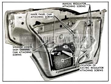
1957 Buick Rear Door Window Regulator Removal-Models 43-63
Position regulator balance arms in line with lift arm to facilitate removal of regulator assembly through access hole.
To remove electric motor from regulator assembly see “REAR DOOR WINDOW REGULATOR ELECTRIC MOTOR ASSEMBLYREMOVAL AND INSTALLATION.”
- To install window regulator assembly, reverse removal procedure.
Before installing window regulator, make sure spring clip on regulator balance arm is properly installed. If clip is damaged, replace with new clip.
When installing center guide shoe into channel of center guide, make sure anti-rattle clip is also engaged in channel of guide.
Removal and Installation of 1957 Buick Rear Door Window Regulator Electric Motor Assembly-Four-Door Bodies
- Remove electric window regulator assembly from door and clamp securely in a vise, as shown in illustration.
NOTE: The position of the regulator clamped in the vise will vary with the type of regulator and position of the lift arm.
CAUTION: BE SURE TO PERFORM STEPS 2 AND 3 BEFORE ATTEMPTING TO REMOVE THE MOTOR FROM THE REGULATOR.
The regulator lift arm, which is under tension from the counterbalance spring can cause serious injury, if the motor is removed without locking the sector in position.
- Drill a 1/4,” hole through sector and back plate at location “A” indicated in illustration.
NOTE: Location of hole in backplate will vary depending on position of sector. Do not locate hole less than 1/2″ away from edge of backplate or sector. Fig. 13-64.
1957 Buick Rear Door Window Electric Regulator Assembly
- Insert a 3/16″ bolt through hole in backplate and sector and install nut to bolt. (Do not tighten nut.)
- Remove the three (3) motor attaching bolts and remove motor assembly from regulator. NOTE: Clean off steel chips from the regulator sector and motor pinion gear after drilling operation.
- To install, reverse removal procedure. Regulator motor rubber pad should be cemented to inner panel side of motor. NOTE: Be sure to remove temporary nut and bolt from regulator after motor is installed.
1957 Buick Rear Door Locking Mechanisms (Models 41-43-63)
All 1957 Buick door locks are the rotary bolt-type lock with the interlock feature. With the interlock feature it is very important that the lock extension engages properly in the striker notch and that, where necessary, striker emergency spacers of the proper thickness are used to obtain proper engagement as described under “DOOR LOCK STRIKER ADJUSTMENTS”.
A redesigned spring clip is used on 1957 Buick door lock levers to secure the connecting rods to the lock levers. A slot in the spring clip provides easier disengagement of the clip, thereby facilitating easier detachment of the lock connecting rods from the lock.
To disengage spring clips, use a screw driver or other suitable tool to slide clip out of engagement. Fig. 13-65 shows a door lock spring clip engaged and disengaged.
1957 Buick Door Lock Spring Clips
Removal and Installation of 1957 Buick Rear Door Lock Assembly (Models 41-43-63)
- Raise 1957 Buick door window. Remove door trim assembly and inner panel water deflector.
- On 41 bodies, through large access hole, disengage spring clips securing remote control and inside locking connecting rods to lock; and detach connecting rods from lock, Fig. 13-66.
1957 Buick Rear Door Locking Mechanism-Model 41
1957 Buick Rear Door Lock Removal
1957 Buick Rear Door Locking Mechanisms-Models 43 and 63
Lower lock between door panels and remove through access hole.
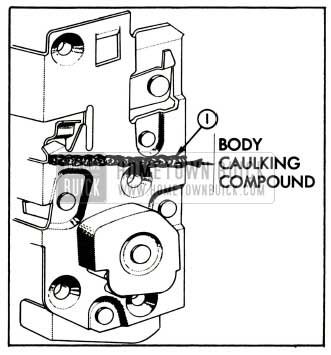
Before installing door lock, apply a ribbon of body caulking compound (approximately 1/4, inch in diameter) across face of lock frame above rotary bolt housing, as indicated in Fig. 13-69.
1957 Buick Door Lock Sealing
After installation of lock and before installation of door inner panel water deflector, adjust door outside handle push button shaft (turn in or out) to provide between 1/32″ and 1/8″ free travel of the push button. Check all operations of door lock.
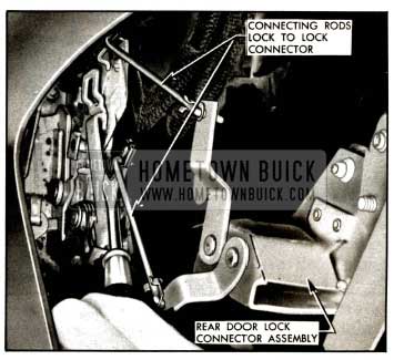
Removal and Installation of 1957 Buick Rear Door Lock Remote Control Assembly and Connecting Rod (Models 41-43-63)
- Remove 1957 Buick door trim assembly. Detach upper portion of door inner panel water deflector sufficiently to gain access to remote control attaching screws.
- Remove remote control attaching screws and remove remote control from connecting rod, Fig. 13-68 and 13-66.
- To remove remote control connecting rod on 43 and 63 rear doors, detach rod from clip on inner panel; then detach rod from door lock connector, Fig. 13-68.
- To remove remote control connecting rod on 41 rear doors, disengage spring clip and detach rod from door lock and clip on inner panel, Fig. 13-66.
- To install door lock remote control and connecting rod, reverse removal procedure. Adjust remote control rearward sufficiently to take up slack in linkage.
Remote Control Adjustments (Models 41-43-63)
- Remove door trim assembly. Detach upper portion of door inner panel water deflector sufficiently to gain access to remote control attaching screws.
- Loosen remote control attaching screws, Fig. 13-68. Move remote control to forward position; then adjust remote control rearward sufficiently to take up slack in linkage. Check operation of door lock before re-sealing inner panel water deflector.
Removal and Installation of Rear Door Inside Locking Rod, Lever, and Connecting Rod (Models 43-63)
- Remove door trim assembly. Detach upper portion of inner panel water deflector sufficiently to gain access to inside locking rod, lever, and connecting rod.
- Remove inside locking rod lever attaching screw, Fig. 13-68, and remove lever spring washer and cup washer. Detach inside locking connecting rod from clip on inner panel; then, detach lever from inside locking connecting rod and remove lever and inside locking rod from door.
- Detach inside locking connecting rod from door lock connector and remove from
- To install inside locking rod, lever, and connecting rod, reverse removal procedure. Check all operations of door lock before installing inner panel water deflector, door trim assembly and inside hardware.
Removal and Installation of 1957 Buick Rear Door Outside Handle (Models 41-43-63)
- Raise door window. Remove door trim assembly and detach upper portion of inner panel water deflector sufficiently to gain access to access holes for door outside handle attaching screws.
- Through access holes for door outside handle attaching screws, Fig. 13-68 and 13-66, remove handle attaching screws; then remove handle and handle gaskets.
- To install rear door outside handle, reverse removal procedure, making sure front and rear gasket is installed between handle and door outer panel.
Adjust (turn in or out) the outside handle push button shaft to provide between 1/32″ and 1/8″ free travel of push button.
Check all operations of door lock before installing door inner panel water deflector, door trim assembly and inside hardware.
Disassembly and Assembly of Rear Door Outside Handle (Models 41-43-63)
- Remove 1957 Buick rear door outside handle.
- Remove spring retainer, stop washer retainer, stop washer, spring, push button and shaft, and sealing washer.
- To assemble rear door outside handle, reverse disassembly procedure. Fig. 13-70 shows the handle assembled.
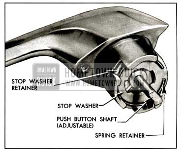
1957 Buick Rear Door Outside Handle Assembly
When installing the handle assembly to the door adjust the push button shaft to provide between 1/32″ and 1/8″ free travel of the push button.
Check all operations of 1957 Buick door lock before installing door inner panel water deflector door trim assembly and inside hardware.
1957 Buick Rear Door Lock Free-Wheeling Adjustment (Models 41-43-63)
When the inside locking rod is in the down position and the lock is set in free-wheeling, it prevents the door from being opened by the operation of the inside handle.
The tool required to perform the free-wheeling adjustment can be made from a piece of rod approximately 1/8″ in diameter. To make tool, cut rod to approximately 7″ length, then bend 3/8″ of rod at one end to form a right angle. The rear door lock may be adjusted “in” or “out” of free-wheeling as follows:
- Lower door window; pull inside locking rod knob to “up” position and remove rear door lock upper attaching screw.
- Insert adjusting tool through screw hole, Fig. 13-71.
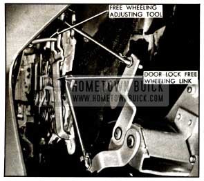
1957 Buick Free Wheeling Adjustment
NOTE: Check all operations of door lock after making a free-wheeling adjustment.
13-9 1957 BUICK CENTER PILLAR (MODELS 43-63)
The 1957 Buick center pillar trim material is cemented to the center pillar. The material is covered along the front and rear edges by pinchweld finishing moldings and over the top by a pinchweld finishing cap. Each molding is secured to the carpet support by one (1) screw while the finishing cap is secured to the top of the assembly by two (2) screws. Prior to installation, the underside of the finishing cap is sealed at the outboard portion of the cap.
Removal and Installation of 1957 Buick Center Pillar Finishing Cap
- Remove two (2) screws from top of cap and remove cap from center pillar.
- To install, first apply sealer to underside of cap as shown in Figure 13-72; then position cap on center pillar and install two (2) attaching screws.
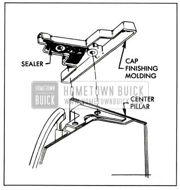
1957 Buick Sealing Center Pillar Cap
Removal and Installation of 1957 Buick Center Pillar Trim Assembly
- Remove 1957 Buick center pillar finishing cap and front and rear pinchweld finishing moldings.
- Starting at sides of trim assembly carefully break cement bond between trim assembly and center pillar and remove trim assembly.
- To install trim assembly clean cementing surface on center pillar to insure a smooth cementing surface.
- Apply an approved trim cement to back of trim assembly. Position foundation portion of trim assembly along crown of center pillar to floor pan brace and cement trim assembly in place.
NOTE: Make certain edges of trim assembly are properly cemented around pinchweld to allow installation of pinchweld finishing moldings.
- Install pinchweld finishing moldings and center pillar finishing cap.
Leave A Comment
You must be logged in to post a comment.