SECTION 13-J 1957 BUICK FRONT END
13-27 WINDSHIELD (SERIES 50-70)
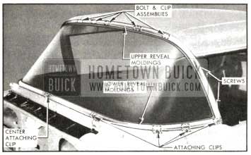
1957 Buick Windshield Reveal Moldings (Except Convertibles)
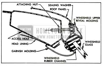
The windshield reveal moldings consist of the following parts; windshield upper reveal molding; windshield side reveal molding, right and left; and windshield lower reveal molding, right and left. The upper reveal molding is secured to the body by means of bolt and clip assemblies and attaching nuts. Access to these attaching nuts is gained by loosening the headlining over the windshield. The side and lower reveal moldings are secured to the body by means of clips and screws which are accessible on the outside of the body.
The windshield reveal moldings are installed in the following sequence: (1) windshield upper and /or lower reveal moldings may be installed independently; (when lower reveal moldings are installed, the right molding is installed first). (2) The side reveal moldings, right and left, are installed last.
- Removal and Installation of Windshield Side Reveal Molding.
- Open door. Remove screws securing side reveal molding to front body hinge pillar. See figure 13-164.
1957 Buick Windshield Reveal Molding Attachment
To remove side reveal molding, first remove windshield drain gutter.
- Disengage side reveal molding from lower reveal molding. Then remove side reveal molding from upper reveal molding by pulling from center of body. See figure 13-164.
- To install, reverse removal procedure. Seal attaching screw holes with body caulking compound.
- Removal and Installation of Windshield Upper Reveal Molding.
- Cover- instrument panel, seat, hood and fenders.
- Remove windshield side and upper garnish moldings and rear view mirror support. (c) Remove sunshades and sunshade supports.
- On 76R and 73 style bodies, loosen side roof rail finishing moldings at front to gain access to headlining.
- Carefully remove tacks and loosen headlining sufficiently to gain access to upper reveal molding attaching nuts. See figure 13-165.
1957 Buick Windshield Reveal Molding Installation
- Remove upper reveal molding attaching nuts. See figure 13-165.
- Remove side reveal moldings. (h) Remove upper reveal molding.
- To install, reverse removal procedure. If necessary, replace bolt and clip assembly sealing washers. See figure 13-165. Seal attaching screw holes with body caulking compound.
- Removal and Installation of Windshield Lower Reveal Molding.
- Cover seat, hood and fenders. Protect adjacent paint finish with masking tape.
- Open door. Remove side reveal molding. See figure 13-164.
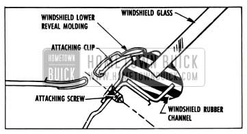
- Remove clip attaching screw from end of lower reveal molding at front body hinge pillar.
- Remove screw, “A,” from lower reveal molding attaching clip which is readily accessible with door open.
- To disengage lower reveal molding from attaching clip, “B,” figure 13-164, slide lower reveal molding outward for distance of about one inch and raise molding. This clip is also shown in figure 13-166.
1957 Buick Windshield Lower Reveal Molding Attachment Procedure
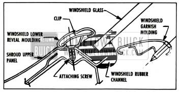
- Remove lower reveal molding by sliding molding off attaching clip “C,” figure 13-164. The cross-section attachment of this clip is shown in figure 13-167.
1957 Buick Windshield Lower Reveal Molding Attachment Instruction
NOTE: The left lower reveal molding slides into the integral center escutcheon of the right lower reveal molding. The right molding is secured at the body center-line by means of a slide-on type center attaching clip. See figure 13-167.
- To install, reverse removal procedure with following exceptions:
- Right lower reveal molding is installed before left molding.
- All lower reveal molding attaching clips are secured to body with screws. When installing clips, such as during windshield glass removal and installation operations, seal screw holes with medium bodied sealer.
Removal and Installation of 1957 Buick Windshield Garnish Moldings and Rear View Mirror Support
The windshield garnish moldings are secured to the body with readily accessible screws. Because of design, the garnish moldings are removed and installed in a definite sequence. The garnish moldings consist of the following parts: side garnish molding, right and left; upper garnish molding, right and left; lower garnish molding, right and left; and the lower garnish molding center escutcheon. The rear view mirror support attaches to the body at the upper center of the windshield opening. The sides of the support are over-lapped by the upper garnish moldings.
- Cover instrument panel, front seat, and adjacent paint and trim parts.
- Remove side and lower center garnish moldings.
- With side garnish moldings removed, remove upper garnish moldings, right and left, then remove rear view mirror support.
- With side garnish moldings removed, remove lower garnish moldings, right and left, including center escutcheon.
- To install, reverse removal procedure.
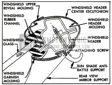
Removal and Installation of 1957 Buick Windshield Header Moldings (Convertibles)
The windshield header moldings are made up of three sections: A right and left section and a center escutcheon.
- Cover instrument panel and seat.
- Lower top.
- Remove windshield side and upper garnish moldings and remove rear view mirror support.
- Remove sunshades, supports, and front roof rail lock strikers.
- Remove side reveal moldings.
- Remove windshield header molding center escutcheon.
- Remove attaching screw from each end of upper reveal molding which also secures windshield header molding.
- Remove windshield header moldings, right and left, by disengaging front edges of moldings from windshield reveal molding. See figure 13-168.
1957 Buick Windshield Header Illustration
- To install, reverse removal procedure.
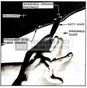
Removal of 1957 Buick Windshield Glass
The windshield is secured to the body by a one-piece rubber channel. With the exception of the convertible styles, the windshield reveal moldings are installed after the windshield installation. On convertible styles, the upper reveal molding is installed in the rubber channel before windshield glass installation.
- Lower top on convertible styles.
- Cover front seat, instrument panel, fenders and hood.
- Remove windshield wiper arm and blade assemblies.
- Remove windshield garnish moldings.
- Remove windshield reveal moldings.
- Apply outward pressure close to edge of glass with palm of hand and, using putty knife, work lip of rubber channel over pinchweld flange. See figure 13-169.
1957 Buick Windshield Glass Removal
- With aid of helper, carefully remove windshield assembly from body and place on covered bench.
- Remove rubber channel from glass.
Checking Body Windshield Opening
It is important that the size and contour of the body windshield opening be checked thoroughly before the installation of a replacement windshield glass. The procedure below outlines the method which can be used to check the windshield opening:
- Check windshield rubber channel for any irregularities.
- Clean off old sealer from around windshield opening and check entire body opening flange for irregularities.
- Support and center new glass in windshield opening with six wood spacers located as shown. CAUTION: Be certain that glass does not strike body metal during this temporary installation. Chipped edges can result in future breaks. See figure 13-170.
1957 Buick Spacer Position for Pinchweld Alignment
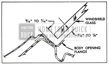
- Figure 13-171 shows a typical cross-section taken through glass and body opening. Spacing between glass and metal should be as follows:
1957 Buick Windshield Glass to Pinchweld Clearances
1957 Buick Windshield Glass Installation and Removal
- Between inside surface of glass and body opening flange spacing should be uniform and from 3/16″ to 1/4″.
- Between edge of glass and body opening spacing should be uniform and when measured in plane of glass should be 5/16″ to 7/16″.
- Mark any sections of body to be re-formed (masking tape applied to body opening can be conveniently marked without damage to the painted surfaces), remove glass, and reform opening as required.
- Check windshield opening again as outlined in step 4. MARK THE GLASS AND BODY so that glass can be centered accurately in opening when installed.
Installation of 1957 Buick Windshield Glass
- Check windshield drain gutter and both left and right drain hose openings for obstructions and clean out if necessary.
- Install rubber channel on glass. On convertible styles, install and center upper reveal molding in rubber channel.
- Insert strong cord in pinchweld cavity of rubber channel completely around windshield. Form loop with cord at bottom center of glass and tape loop to inside of glass. See figure 13-173.
1957 Buick Windshield Glass Installation
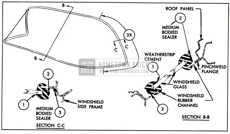
- Apply a ribbon of medium-bodied sealer completely around base of rubber channel as indicated at 2 in figure 13-172. In addition, apply a ribbon of sealer along pinchweld flange as indicated at 3 in figure 13-172. This seal is to be applied at each side of windshield opening as indicated by distance 3X.
- With aid of helper, position glass in opening and center glass between windshield pillars.
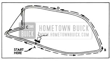
- Use care when positioning glass close to windshield opening for cord pulling operation. Do not use excessive pressures or blows of any type during or after glass installation. Have helper inside pull cord slowly in following sequence to seat lip of channel over pinchweld. (Figure 13-173).
- Along bottom, “a” to point “b,” as shown.
- Along bottom, “a” to point “c,” as shown.
- Along top, “c” to point “d,” as shown.
- Along top, “b” to point “d,” as shown.
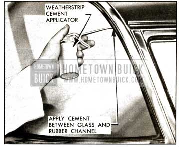
- Use weatherstrip cement to seal between outside lip of rubber channel and glass. See figure 13-174.
1957 Buick Windshield Rubber Channel Sealing
- Clean off all excess sealer and install previously removed parts. Remove protective coverings.
13-28 1957 BUICK WINDSHIELD WIPER (SERIES 50-70)
1957 Buick Cam-O-Matic Windshield Wiper Transmissions
The Cam-0-Matic windshield wiper transmission is designed with a windshield wiper arm cam on the transmission shaft. A follower on the wiper arm engages with the cam maintaining blade-to-glass contact. The wiper arm cam is secured to the transmission shaft by the transmission spanner nut. To remove the wiper arm assembly raise the upper section of the wiper arm to disengage the cam follower from the cam. With wiper arm in raised position, carefully pull or pry arm from transmission shaft.
Removal and Installation of 1957 Buick Windshield Wiper Motor
The windshield wiper motor attaches to the auxiliary drive assembly at the forward side of the dash panel.
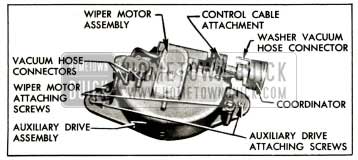
- Remove two wiper motor to support attaching screws with washers and disengage motor from auxiliary drive assembly. See figure 13-175.
1957 Buick Windshield Wiper Motor
- Disconnect vacuum hoses from wiper motor and washer coordinator.
- Disconnect wiper motor control cable at wiper motor and remove wiper motor. See figure 13-175.
- To install wiper motor, reverse removal procedure and check operation of motor.
Removal of 1957 Buick Windshield Wiper Motor Auxiliary Drive Assembly
The auxiliary drive assembly attaches to the forward side of the dash panel. The wiper motor attaches to the drive at this location. The drive assembly consists of two pairs of pulleys, a pair of copper notched pulleys and a pair of steel notched pulleys, to which the ends of the transmission cables are attached. The pulleys are designed to operate simultaneously as an integral unit.
- Remove instrument panel center section.
- Adjust wiper transmission cables to slack position. See “Wiper Transmission Cable Adjustment.”
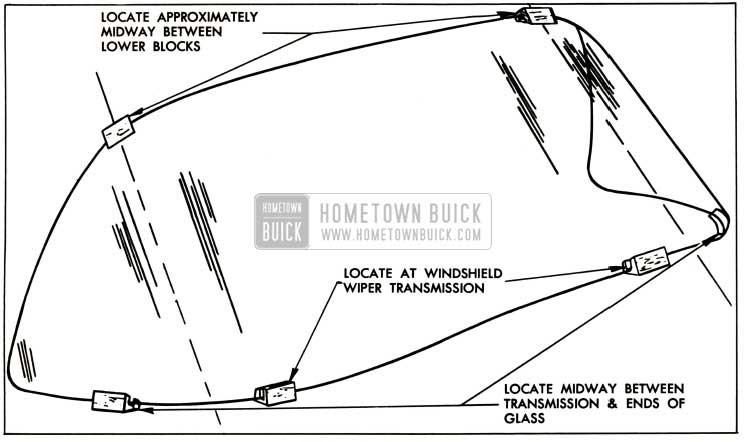
- Observe and note wiper transmission cable to auxiliary drive attachment to assure proper installation, then disconnect cables from pulleys. See figure 13-176.
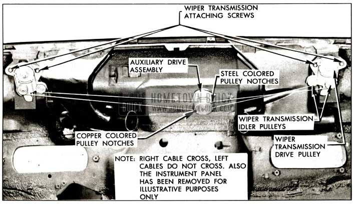
1957 Buick Wiper Transmission and Auxiliary Drive Installation
- Disconnect wiper motor from auxiliary drive by removing motor attaching screws. See figure 13-175.
- Remove auxiliary drive to dash attaching screws. Carefully break seal between auxiliary drive and gasket on body and remove drive. See figure 13-175.
Installation of Windshield Wiper Motor Auxiliary Drive Assembly
- If necessary, cement new auxiliary drive gasket to body with weatherstrip cement and install auxiliary drive. See figure 13-175.
- Install windshield wiper motor. See figure 13-175.
- Inside of body, attach wiper transmission cables to auxiliary drive.
IMPORTANT: The “right” wiper transmission cables attach to the “outer” two (of four) drive pulleys and the “left” wiper transmission cables attach to the “inner” two (of four) drive pulleys as shown. Also, copper colored cable ends must be installed to copper colored pulley notches and steel colored cable ends to steel colored pulley notches. The right transmission cables cross and the left transmission cables do not cross. See figure 13-176.
- Adjust cable tension as required. See “Wiper Transmission Cable Adjustment.”
- Check auxiliary drive for proper operation.
- Install instrument panel center section.
Removal of 1957 Buick Windshield Wiper Transmission
The 1957 Buick windshield wiper transmission has been redesigned and attaches to the body by means of a spanner nut. Since an additional spanner nut is required to secure the escutcheon, the new transmission service procedures now involve two spanner nuts, each of a different size. The new transmissions are designed with “idler” pulleys in addition to “drive” pulleys which play an important role in routing the power from the wiper motor to the windshield wipers. The new wiper transmissions retain the “push-button” cable adjustment feature.
- Remove 1957 Buick wiper arm and blade assemblies.
- Remove instrument panel center section.
- Adjust wiper transmission cables to slack position. See “Wiper Transmission Cable Adjustment.”
- Observe and note attachment of transmission cables at auxiliary drive pulleys to assure proper installation, then disconnect cables from auxiliary drive pulleys. See figure 13-176.
- Using wrench 6592, remove wiper transmission spanner nut; then remove cam, (if equipped with Cam-0-Matic feature) washer, and escutcheon. Disconnect washer hose to remove escutcheon.
CAUTION: Tape hose to body to simplify installation. See figure 13-177.
1957 Buick Windshield Wiper Transmission
- Using wrench 6592, remove wiper transmission spanner nut and spacer. See figure 13-178.
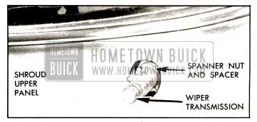
1957 Buick Windshield Wiper Transmission Attachment
- Remove transmission attaching screws. Break seal between transmission gasket and body and remove transmission. See figure 13-176.
Installation of 1957 Buick Windshield Wiper Transmission
- If necessary replace gasket and arrange transmission component parts for installation. See figure 13-179.
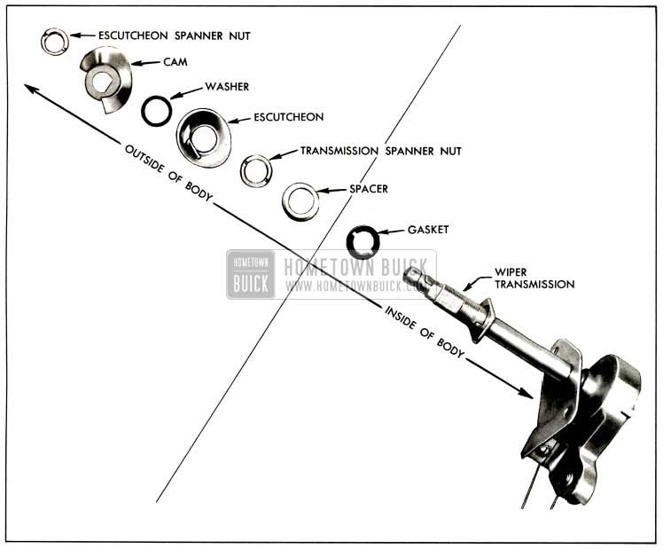
1957 Buick Windshield Wiper Transmission Component Parts-Exploded View
- Inside of body, position gasket on transmission and position transmission in body. “Start” attaching screws but do not tighten them at this time. See figure 13-176.
- Outside of body, position transmission spacer and spanner nut. Check alignment of wiper transmission and tighten spanner nut with wrench 6592. Then, inside of body, tighten wiper transmission attaching screws. See figure 13-179.
- Connect washer hose to escutcheon. Position escutcheon washer and cam and install spanner nut with wrench 6592. See figure 13-177.
- Inside of body, attach transmission cables to auxiliary drive pulleys as shown. NOTE: The “right” transmission cables attach to the two “outer” pulleys of the auxiliary drive, and the left transmission cables attach to the two “inner” pulleys of the auxiliary drive. IMPORTANT: The copper colored cable ends must be installed to the copper colored pulley notches and the steel colored cable ends must be installed on the steel colored pulley notches. The right transmission cables cross and the left transmission cables do not cross. Fig. 13-176.
- Restore cable tension” as required. See “Wiper Transmission Cable Adjustment.”
- Install wiper arm and blade assemblies and check operation of wiper transmission.
- Install instrument panel center section.
Windshield Wiper Transmission Cable Adjustment
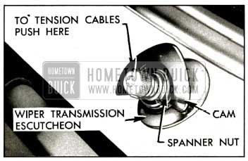
The transmission cables are tensioned by “spring-loaded” pulleys. When the end of the transmission shaft is pushed “in” as shown in the illustration, the spring-loaded pulleys unlock and tension the cables. To obtain slack in the wiper transmission cables, proceed as follows:
- On wiper transmissions with the Cam-O-Matic feature, remove wiper arm by pulling upper section of arm upward to disengage cam follower from cam, then pull arm from transmission shaft. Push “in” end of transmission shaft.
NOTE: If the wiper transmission does not have the Cam-0-Matic feature, push “in” the base of the wiper arm where the arm fits over the transmission shaft to adjust tension in cables.
- While pulleys are unlocked, have helper inside of car pull cable to obtain slack. When sufficient slack is obtained, release end of transmission shaft to lock cable in slack position.
- To restore tension in cables, push “in” on end of transmission shaft. Repeat operation on opposite transmission.
NOTE: Loose cables cause blade slap or overtravel at end of stroke. If this condition exists, adjust tension of cables as outlined in step “8.” See figure 18-177.
Removal and Installation of Windshield Wiper Control
The windshield wiper control is attached to the left side of the instrument panel. The windshield washer is controlled by a new type “pushbutton” and the motor is controlled by a “push-pull” type lever control.
- Cover seat and fenders.
- Disconnect wiper control cable from motor. It is necessary first to disconnect motor from auxiliary drive to gain access to wiper control attachment.
- Tie strong cord or wire to control cable.
- Remove attaching screws from wiper control and disconnect washer control hose. See figure 13-180.
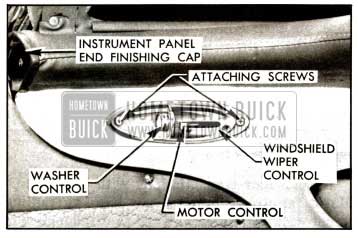
1957 Buick Windshield Wiper Control Attachment
- Remove wiper control and cable as an assembly and disconnect strong cord.
- To install, reverse removal procedure. Use strong cord previously installed to help in correctly positioning cable through openings in front end.
- Position control cable correctly at motor and check operation of wiper control.
13-29 1957 BUICK INSTRUMENT PANEL (SERIES 50-70)
The instrument panel assembly consists of a three-piece upper section and a one-piece lower section. While the complete instrument panel assembly is removable, service access to the windshield wiper transmissions, the auxiliary drive and other parts covered by the instrument panel can be gained by removing the upper center section only. To gain access to the center section front attaching screws, it is necessary to remove the windshield lower center garnish molding. The instrument panel cover corresponds to the construction of the upper section and is serviced as a three-piece unit. The instrument panel lower section cover, of two-piece construction, attaches to the compartment door and to the right side of the instrument panel.
Removal and Installation of 1957 Buick Instrument Panel Compartment Door
- Open door and scribe position of hinge on door.
- Remove door stop attaching screws on each side of door and disconnect compartment door stops. See figure 13-181.
1957 Buick Wiper Transmission and Auxiliary Drive Installation
- Remove hinge to door attaching screws and remove door. See figure 13-181.
- To install, reverse removal procedure. Align door according to previously made scribe marks and tighten attaching screws.
Adjustment of Instrument Panel Compartment Door
- The screw holes in the compartment door side of the hinge are elongated to permit “up and down” adjustment of the door. See figure 13-181.
- The screw holes in the instrument panel side of the hinge are elongated to permit “side-to-side” adjustment of the door. See figure 13-181.
- The instrument panel attaching screw holes for the lock striker are elongated to permit “fore and aft” adjustment of the top of the door.
Removal and Installation of Instrument Panel Compartment Door Lock Cylinder
- Note position of lock cylinder key opening when in the locked and unlocked position.
- Insert key in lock cylinder and open door.
- Hold lock bolt in rear position, turn key clockwise 90° from unlocked position, and remove cylinder with key. See figure 13-182.
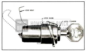
1957 Buick Instrument Panel Compartment Door Lock Cylinder Removal
- To install, reverse removal procedure.
Removal and Installation of Instrument Panel Compartment Door Lock Knob
- Open door and remove door lock knob to retainer attaching screw. See figure 13-181.
- Remove lock knob retainer and lock knob.
- To install, reverse removal procedure.
Removal and Installation of 1957 Buick Instrument Panel – Upper Section
- Cover front seat.
- Remove windshield side and lower garnish moldings and lower end finishing caps.
- Remove center section by removing attaching screws along front and rear edges of center section. See figure 13-183.
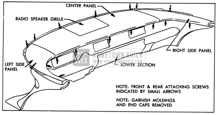
1957 Buick Instrument Panel Upper Section Attachment Illustration
- Remove side sections by removing attaching screws from upper and lower edges of side sections.
- To remove radio speaker grille, turn center section over, remove grille attaching nuts and remove grille.
- To install, reverse removal procedure. Check proper positioning of instrument panel to support silencers in front attaching holes. See figure 13-183.
Removal of Instrument Panel Cover – Upper and Lower
The upper cover is standard on all styles. The lower cover is standard on the Roadmaster Series but is optional equipment on all other styles.
The instrument panel upper section cover consists of a formed plastic and cotton padding and rubber padding. The upper section cover corresponds to the component parts of the instrument panel and is serviced as a three-piece unit: a left and right side section and a center section.
The instrument panel lower section cover is made up of a new plastic construction and consists of two parts: one cover attaches to the compartment door and the other part attaches to the lower right side of the instrument panel.
The upper section cover parts are secured to the panel by means of trim cement. The lower section cover parts are fastened to the panel by means of attaching screws.
- Remove upper section of instrument panel and remove radio speaker grille from center section.
- Carefully detach cemented coverings from perimeter of each panel and remove coverings from panels.
CAUTION: Unless required, do not remove cotton or rubber pads from panels. See figure 13-181.
- To remove lower cover from compartment door, open door, remove cover attaching screws, and disengage cover attaching tabs.
- To remove lower cover from right side of instrument panel, remove cover attaching screws from back side of instrument panel.
Installation of Instrument Panel Cover – Upper and Lower
- Clean and dry cementing surfaces on each section of instrument panel.
- If necessary, repair or replace cotton padding.
- Apply trim cement to cementing surfaces of cover and panel. Allow cement to dry for several minutes. See figure 13-184.
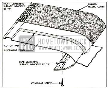
1957 Buick Instrument Panel Upper Cover Installation
- Position side cover on each side panel. Check cover alignment and press cemented surfaces together firmly to obtain a good bond. See figure 13-184.
- Position cover on center panel. Line up radio speaker grille opening of cover with panel and press cover material firmly in place. Then align and secure front, rear, and side sections of cover as shown. Install radio speaker grille. See figure 13-184.
- Clean up and install upper sections of instrument panel. Install side sections first. Then install all other parts previously removed.
- To install lower covers, reverse removal procedure.
- Open door. Remove screws securing side reveal molding to front body hinge pillar. See figure 13-164.
Leave A Comment
You must be logged in to post a comment.