INTRODUCTION, CARE OF 1957 BUICK BODY, AND SERIES 40-60 FRONT END
1 3-1 INTRODUCTION
- General Information
This manual contains the essential removal, installation, adjustment, and maintenance procedures necessary for ordinary servicing of the Fisher bodies on 1957 Buick automobiles. These procedures can be performed by any competent mechanic without specialized experience in 1957 Buick body repair work and can generally be accomplished using the tools and equipment available in any service shop. Special tools required are identified by tool numbers and are available through Kent-Moore Organization, Inc., General Motors Building, Detroit 2, Michigan.
This manual takes the place of the Fisher Service News which will no longer be published. It also replaces Group 13 (Body) of the Buick Service Manual. (Formerly called Shop Manual). The first edition of the 1957 Buick body manual will therefore carry over the Group 13 designation.
All service procedures and illustrations used in this manual were furnished by Fisher Body Division, Product Service Activity. All changes and corrections to this manual will be published in Buick Product Service Bulletins. All issues of the BPS Bulletins should be kept readily available, as their information supersedes the corresponding information in the manual.
Group 13 is divided into Sections as shown on the first page. Sections bear the Group number and letters A, B, C, etc., in alphabetical order. The first page of each Section lists the contents of that section.
Group 13 is also divided into Paragraphs which are numbered consecutively through the entire manual. Paragraphs are divided into Sub-paragraphs. These are lettered in alphabetical order within the paragraph.
Pages and illustrations are numbered consecutively through the entire manual. The number consists of the Group number followed by the Page or Figure number. Page numbers are printed in the upper outer corners of all pages. All cross references are made by Paragraph numbers.
1957 Buick Fisher Body Number Plate
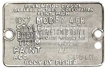
Complete identification of each body as required for service is provided by a plate riveted to the cowl at left of center under the hood. See figure 13-1. This plate should never be destroyed; if removed during body repairs it should be reinstalled in original location.
1957 Buick Fisher Body Number Plate
The Style Number and Body Number always should be furnished on every body parts order, and on warranty claims and Product Reports relative to bodies. In addition, the Trim Number or the Paint Number should be furnished if the subject relates to trim or paint.
The Style Number is a combination of the year, the division number, the series, and the style of the body. In figure 13-1, 57 represents the model year 1957; the first digit 4 indicates Buick Motor Division; the second digit 4 indicates Series 40; 37 indicates the 2-door Riviera body style. An X following the body style indicates that the body is equipped with electric power assists.
The Body Number is the production serial number of the 1957 Buick body. The prefix letter denotes the plant in which the body was built. In figure 13-1, G indicates the Flint plant.
The Trim Number furnishes the key to trim color and material. Trim colors and materials specified for each trim number are given in The Buick Master Parts List.
The Paint Number furnishes the key to the color combination and paint specifications.
Paint colors and the manufacturer’s numbers specified for each paint combination number are given in the Buick Master Parts List.
Body Style Numbers for All Models
In the service procedures given in Group 13 the last two digits of the 1957 Buick body style numbers are used where necessary to distinguish differences between bodies. Body style numbers of all 1957 Buick models are as follows:
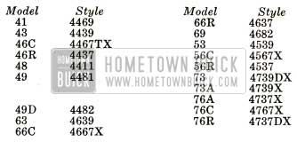
1957 Buick Body Style Numbers
13-2 CARE OF BODY FINISH, PLATED PARTS, AND TRIM
Care of Paint
Care should always be used in applying polishes. Particular care should be observed when the car is new and in using preparatory cleaners which have abrasive properties, regardless of age of the car, because unskilled application of such cleaners will result in rubbed through or thin spots in the paint. Polishes containing wax should be applied sparingly and thoroughly rubbed to remove any surplus. Excessive coatings of wax tend to cloud the paint and destroy its natural lustre, besides acting as a binder for the accumulation of dirt.
When retouching of paint is required in service the paint should be the same number as specified for the paint combination number on the body number plate (fig. 13-1). Unless the new paint contains the same pigments in the same proportion as the original paint, the new paint may weather out off-color even though it appears to blend with the original paint at time of application.
Care of Chrome Plated Parts
Chrome plated parts rust or corrode because chemical agents present in road silt and traffic film seep through pores in the plating and attack the underlying base metal. A plating of nickel is applied underneath the chrome to seal the plating and protect the base metal.
Deterioration of chrome plated parts can be avoided by keeping the parts clean and by periodic application of a preservative which will aid in retarding seepage of destructive agents through the plating. Plated parts should be washed with clear water only, using a mild detergent such as Du Pont Car Wash when necessary. Do not use scouring powders, cleaning compounds, or stiff brushes. An application of Buick Chrome Preservative (group 8.800) every thirty days as instructed on the container will materially aid in maintaining lustre and retarding deterioration of chrome plated parts.
Cleaning 1957 Buick Body Trim Fabric
The cloth headlining has a long nap, therefore, a great deal of care must be used to prevent damage when cleaning it.
A soft brush should be used to remove lint or threads from the headlining and the nap should be brushed in even strokes, brushing from the rear to the front.
It is not recommended that air under pressure be used for removing threads or lint because of the danger of matting and streaking the nap. If an air hose is used, however, it is extremely important to hold the nozzle at least 12 or 16 inches away from the headlining with a moderate air stream flowing from the rear to the front.
There are basically two different types of fabric cleaners on the market:
- Volatile cleaners such as naphtha, gasoline, carbon-tetrachloride and many others that are colorless liquids having great solvent powers for grease and oil.
- Alkaline cleaners, soaps and water mixtures which generally emulsify stains satisfactorily but at possible risk to the removal of the color or finish of the fabric.
For the removal of spots caused by ordinary soilage, we definitely recommend the “volatile type cleaner,” preferably a mixture of carbontetrachloride and cleaner’s naphtha.
Do not use any gasoline which is colored or which contains tetra-ethyl lead. Do not use volatile fire extinguisher fluid.
Careful application of the following procedure is a prime factor in obtaining satisfactory results and if followed closely will prevent the appearance of unsightly rings. The evident slowness of the method is compensated for by the superior results obtained.
- Obtain, cut and fold several small swatches of clean cheesecloth or other fabrics suitable for this purpose.
- With a brush or whisk broom of medium stiffness, brush away all loose particles of dirt and soil.
- Immerse the small cloth swatch in cleaning solution, wring out and allow medium evaporation.
- Place cloth on soiled spot several times using no friction and only slight tapping pressure. This will pick up loose particles which are too embedded to be removed in the brushing operation. This operation should be repeated several times-in each instance using a new clean area of the cloth. Remember the solvent power of the cleaner does the work and only a minimum of pressure should be applied.
- Immerse a new cloth in cleaner, wring out thoroughly, open and allow to evaporate until barely damp. Apply increased pressure and rub soil area in a backward and forward motion (not circular). The cleaning cloth should be reversed several times in this operation.
- Immerse third cloth, wring out, allow evaporation and apply to both the soil and area surrounding same, using a light brisk motion.
- Repeat brushing operation.
Cleaning Folding Top and Back Curtain-Convertible
The top should be washed frequently with neutral type soap suds and lukewarm water. A brush with soft bristles should be used. Generous quantities of clear water should be applied over the entire top to remove any trace of soap which might remain.
If the top requires additional cleaning after using soap and water, a mild foaming type cleanser can be used. A small hand brush having soft or nylon bristles should be used for scrubbing. Add water to the cleanser until a soapy consistency is attained and clean approximately two square feet of the top at one time. After scrubbing, remove the cleanser with a sponge. Care must be exercised to keep the cleanser from running down and across the body finish which may cause streaks. After the entire top has been cleaned, rinse the top generously with clear water to remove any trace of cleanser which might remain. If desired, the top can be supported from the underside during the scrubbing operations.
The flexible plastic window in the back curtain is susceptible to scratches and abrasions, therefore caution must be used in cleaning it. When removing road dust use a soft cotton cloth moistened with water and wipe cross-wise of the window. DO NOT USE A DRY CLOTH.
If further cleaning is required, use cold or tepid (not hot) water and mild neutral soap suds. After washing rinse with clear water and wipe with a slightly moistened clean soft cloth.
CAUTION: Never use solvents or cleaners of alcoholic or other chemical content as these liquids may have a deteriorating effect on the plastic window.
Care and Cleaning of Leather Seats
Care of genuine leather is a relatively simple but important matter. If dirt accumulates on the surface, this generates into a hard grit which under pressure will cut the finish and cause the leather to crack or bleed color. The surface should be gone over occasionally with a dry cloth and if dirt should accumulate, the following cleaning instructions should be used:
- Using lukewarm water and a neutral soap, work up a thick suds on a piece of cheesecloth and apply it to leather surface.
- Go over leather surface again using only a damp cloth and no soap.
- Wipe leather dry with a soft cloth.
NOTE: Polishes and cleaners used for auto body finishes, volatile and other clear cleaners, naphtha, furniture polishes, oils, varnishes or household cleansing and bleaching agents should never be used on leather seats.
13-3 WINDSHIELD (SERIES 40-60)
Windshield Reveal Moldings (Except Convertibles)
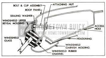
The windshield reveal moldings consist of the following parts: windshield upper reveal molding; right and left; and windshield lower reveal molding, right and left. Center escutcheons are integral on the right upper and lower reveal moldings. Each upper reveal molding is secured to the body by means of bolt and clip assemblies and attaching nuts across the top of the windshield; by means of screws along the front hinge pillars; and by a slide on retention at the lower end. Access to the attaching nuts is gained by loosening the headlining over the windshield. The lower reveal moldings are secured to the body by means of clips and screws which are accessible outside of the 1957 Buick body.
- Windshield Upper Reveal Molding Removal and Installation
- Cover instrument panel, seat, hood and fenders.
- Remove side garnish moldings, upper garnish moldings, and rear view mirror supports.
- Remove sunshades and supports.
- Carefully remove tacks and loosen headlining sufficiently over windshield to gain access to upper reveal molding attaching nuts. See figure 13-3.
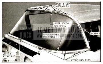
1957 Buick Windshield and Reveal Molding Installation
- Cover hood and fenders. Protect adjacent paint finish with masking tape.
- Open door. Remove attaching screws securing upper reveal molding along front body hinge pillar. See figure 13-4.
1957 Buick Windshield Reveal Molding Attachment Screws
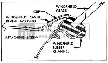
1957 Buick Windshield Lower Reveal Molding Attachment
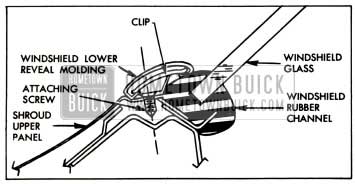
1957 Buick Windshield Lower Reveal Molding Attachment View
NOTE: The left lower reveal molding slides into the integral center escutcheon of the right lower reveal molding. The right molding is secured at the body center line by means of a center attaching clip, figure 13-6.
- Right lower reveal molding is installed before left molding.
- All lower reveal molding attaching clips are secured to body with screws. When installing attaching clips, such as during windshield glass removal and installation operation, seal screw holes with medium bodied sealer.
- Removal and Installation of Windshield Sid e Reveal Moldings (Convertibles)
- Lower top.
- Cover instrument panel and seat.
- Open door. Remove screws securing side reveal molding to front body hinge pillar and remove windshield lower corner gutter.
- Disengage side reveal molding from upper and lower reveal molding and remove molding.
- To install, reverse removal procedure. Seal attaching screw holes with body caulking compound. Remove protective covers.
Removal and Installation of Windshield Garnish Moldings and Rear View Mirror Support
The windshield garnish moldings are secured to the 1957 Buick body with readily accessible screws. Because of design, the garnish moldings are removed and installed in a definite sequence. The garnish moldings consist of the following parts: side garnish molding, right and left; upper garnish molding, right and left; lower garnish molding, right, left and center. The rear view mirror support attaches to the body at the upper center of the windshield opening. The sides of the support are overlapped by the upper garnish moldings.
- Cover instrument panel, front seat, and adjacent paint and trim parts.
- Remove side and lower center garnish moldings.
- With side garnish moldings removed, remove upper garnish moldings, right and left, then remove rear view mirror support.
- With side garnish moldings removed, remove lower garnish moldings, right and left.
- To install, reverse removal procedure and remove protective coverings.
Removal and Installation of Windshield Header Moldings (Convertibles)
The windshield header moldings are made up of three sections: A right and left section and a center escutcheon.
- Cover instrument panel and seat.
- Lower top.
- Remove windshield side and upper garnish moldings and remove rear view mirror support.
- Remove sunshades, sunshade supports and sunshade rod retainers.
- Remove front roof rail lock strikers (2).
- Remove side reveal moldings. See: “Side Reveal Molding Removal.”
- Remove windshield header molding center escutcheon.
- From each end of upper reveal molding remove screw and shim which also secures windshield header molding.
- Remove windshield header molding, right and left, by disengaging front edges of moldings from windshield reveal molding.
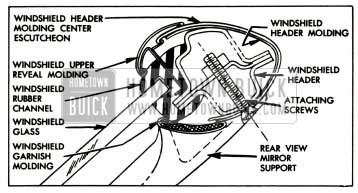
1957 Buick Windshield Header
Removal of Windshield Glass
The windshield is secured to the body by a one-piece rubber channel. With the exception of the convertible styles, the windshield reveal moldings are installed after the windshield installation. On convertible styles, the upper reveal molding is installed in the rubber channel before the windshield assembly is installed.
- Lower top on convertible styles.
- Cover front seat, instrument panel, fenders and hood.
- Remove windshield wiper arm and blade assemblies.
- Remove windshield garnish moldings and rear view mirror support.
- Remove windshield reveal moldings.
- Apply outward pressure close to edge of glass with palm of hand and, using putty knife, work lip of rubber channel over pinchweld flange. See figure 13-8.
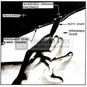
1957 Buick Windshield Glass Removal
Checking 1957 Buick Body Windshield Opening
It is important that the size and contour of the body windshield opening be checked thoroughly before the installation of a replacement windshield glass. The procedure below outlines the method which can be used to check the windshield opening:
- Check windshield rubber channel for any irregularities.
- Clean off old sealer from around windshield opening and check entire body opening flange for irregularities.
- Support and center new glass in windshield opening with six wood spacers located as shown.
CAUTION: Be certain that glass does not strike body metal during this temporary installation. Chipped edges can result in future breaks. See figure 13-9.
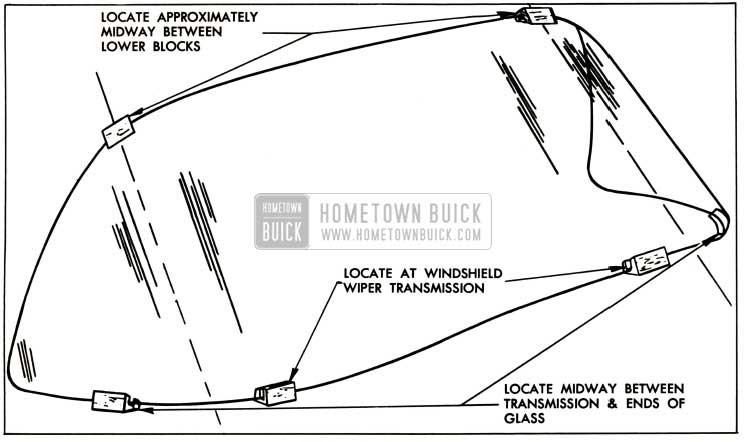
1957 Buick Spacer Position for Pinchweld Alignment
- Figure 13-10 shows a typical cross-section taken through glass and body opening. Spacing between glass and metal should be as follows:
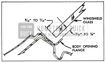
1957 Buick Windshield Glass to Pinchweld Clearances
- Between inside surface of glass and body opening flange spacing should be uniform and from 3/16″ to 1/4″.
- Between edge of glass and body opening, spacing should be uniform and when measured in plane of glass should be 3/16″ to 7/16″.
Installation of Windshield Glass
- Check windshield drain gutter and both left and right drain hose openings for obstructions and clean out if necessary.
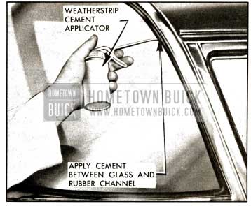
- Install rubber channel on glass. See figure 13-11.
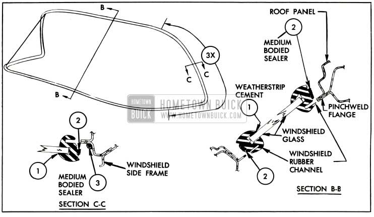
1957 Buick Windshield Glass Sealing
On convertible styles, install and center upper reveal molding in rubber channel.
1957 Buick Windshield Glass Installation
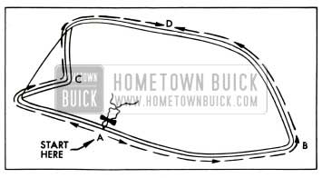
- Along bottom, “a” to point “b”, as shown.
- Along bottom, “a” to point “c”, as shown.
- Along top, “c” to point “d”, as shown. (d) Along top, “b” to point “d”, as shown.
1957 Buick Windshield Rubber Channel Sealing
13-4 WINDSHIELD WIPER (SERIES 40-60)
Cam-O-Matic Windshield Wiper Transmissions
The Cam-O-Matic windshield wiper transmission is designed with a windshield wiper arm cam on the transmission shaft. A follower on the wiper arm engages with the cam maintaining blade-to-glass contact. The wiper arm cam is secured to the transmission shaft by the transmission spanner nut. To remove the wiper arm assembly raise the upper section of the wiper arm to disengage the cam follower from the cam. With wiper arm in raised position, carefully remove arm from transmission shaft.
Removal and Installation of Windshield Wiper Motor
The windshield wiper motor attaches to the auxiliary drive assembly at the forward side of the dash panel.
- Remove two wiper motor to support attaching screws with washers and disengage motor from auxiliary drive assembly. See figure 13-14.
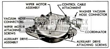
1957 Buick Windshield Wiper Motor
Removal of Windshield Wiper Motor Auxiliary Drive
The auxiliary drive assembly attaches to the forward side of the dash panel. The wiper motor attaches to the drive at this location. The drive assembly consists of two pairs of pulleys, a pair of copper colored notched pulleys and a pair of steel colored notched pulleys, to which the ends of the transmission cables are attached. The pulleys are designed to operate simultaneously as an integral unit.
- Remove instrument panel upper center section.
- Adjust wiper transmission cables to slack position. See “Wiper Transmission Cable Adjustment”.
- Observe and note wiper transmission cable to auxiliary drive attachment to assure proper installation, then disconnect cables from pulleys. See figure 13-15.
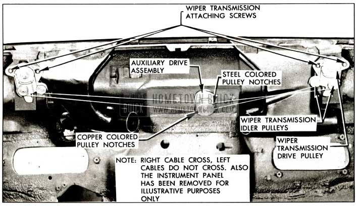
1957 Buick Wiper Transmission and Auxiliary Drive Installation
Installation of Windshield Wiper Motor Auxiliary Drive
- If necessary, cement new auxiliary drive gasket to body with weatherstrip cement and install auxiliary drive. See figure 13-14.
- Install windshield wiper motor. See figure 13-14.
- Inside of body, attach wiper transmission cables to auxiliary drive.
IMPORTANT: The “right” wiper transmission cables attach to the “outer” two (of four) drive pulleys and the “left” wiper transmission cables attach to the “inner” two (of four) drive pulleys as shown. Also, copper colored cable ends must be installed to copper colored pulley notches and steel colored cable ends to steel colored pulley notches. The right transmission cables cross and the left transmission cables do not cross. See figure 13-15.
- Adjust cable tension as required. See “Wiper Transmission Cable Adjustment”.
- Check auxiliary drive for proper operation.
- Install instrument panel upper center section.
Removal of Windshield Wiper Transmission
The windshield wiper transmission has been redesigned and attaches to the body by means of a spanner nut. Since an additional spanner nut is required to secure the escutcheon, the new transmission service procedures now involve two spanner nuts, each of a different size. The new transmissions are designed with “idler” pulleys in addition to “drive” pulleys which play an important role in routing the power from the wiper motor to the windshield wipers. The new wiper transmissions retain the “push-button” cable tensioner feature.
- Remove wiper arm and blade assemblies.
- Remove instrument panel center section.
- Adjust wiper transmission cables to slack position. See “Wiper Transmission Cable Adjustment”.
- Observe and note attachment of transmission cables at auxiliary drive pulleys to assure proper installation, then disconnect cables from auxiliary drive pulleys. See figure 13-15.
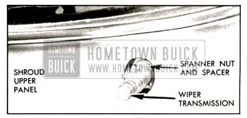
- Using Wrench 6592, remove wiper transmission escutcheon spanner nut; then remove cam, (if equipped with Cam-0-Matic feature) washer, and escutcheon. Disconnect washer hose to remove escutcheon and tape hose to shroud upper panel to facilitate installation. See figure 13-16.
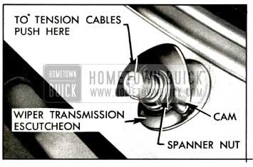
1957 Buick Windshield Wiper Transmission Escutcheon
1957 Buick Windshield Wiper Transmission Attachment
Installation of Windshield Wiper Transmission
- If necessary replace gasket and arrange transmission component parts for installation. See figure 13-18.
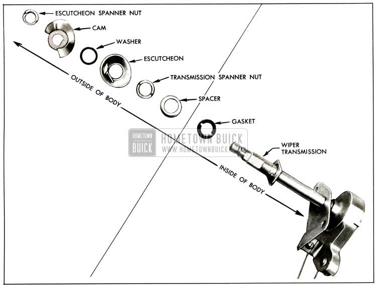
1957 Buick Windshield Wiper Transmission Component Parts
IMPORTANT: The copper colored cable ends must be installed to the copper colored pulley notches and the steel colored cable ends must be installed on the steel colored pulley notches.
NOTE: The right transmission cables cross and the left transmission cables do not cross. See figure 13-15.
- Restore cable tension as required. See “Wiper Transmission Cable Adjustment”.
- Install wiper arm and blade assemblies and check operation of wiper transmission.
- Install instrument panel upper center section.
Windshield Wiper Transmission Cable Adjustment
The transmission cables are tensioned by “spring-loaded” pulleys. When the end of the transmission shaft is pushed “in” as shown in the illustration, the spring-loaded pulleys unlock and tension the cables. To obtain slack in the wiper transmission cables, proceed as follows:
- On wiper transmissions with the Cam-O-Matic feature, remove wiper arm by pulling upper section of arm upward to disengage cam follower from cam, then pull arm from transmission shaft. Push “in” end of transmission shaft.
NOTE: If the wiper transmission does not have the Cam-0-Matic feature, push “in” the base of the wiper arm where the arm fits over the transmission shaft to adjust tension in cables.
- While pulleys are unlocked, have helper inside of car pull cable to obtain slack. When sufficient slack is obtained, release end of transmission shaft to lock cable in slack position.
- To restore tension in cables, push “in” on end of transmission shaft. Repeat operation on opposite transmission.
NOTE: Loose cables cause blade slap or overtravel at end of stroke. If this condition exists, adjust tension of cables as outlined in step “3”. See Figure 13-16.
Removal and Installation of Windshield Wiper Control
The windshield wiper control is attached to the left side of the instrument panel. The windshield washer is controlled by a new type “push-button” and the motor is controlled by a “push-pull” type lever control.
- Cover seat and fenders.
- Disconnect wiper control cable from motor.
NOTE: It is necessary first to disconnect motor from auxiliary drive to gain access to wiper control attachment.
- Tie strong cord or wire to control cable.
- Remove attaching screws from wiper control on instrument panel and disconnect washer control hose. See figure 13-19.
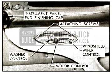
1957 Buick Windshield Wiper Control Attachment
13-5 INSTRUMENT PANEL (SERIES 40-60)
The instrument panel assembly consists of a three-piece upper section and a one-piece lower section. While the complete instrument panel assembly is removable, service access to the windshield wiper transmissions, the auxiliary drive and other parts covered by the instrument panel can be gained by removing the upper center section only. To gain access to the center section front attaching screws, it is necessary to remove the windshield lower center garnish molding. The instrument panel cover corresponds to the construction of the upper section and is serviced as a three-piece unit. The instrument panel lower section cover, of two-piece construction, attaches to the compartment door and to the right of the instrument panel.
Removal and Installation of Instrument Panel Compartment Door
- Open door and scribe position of hinge on door.
- Remove door stop attaching screws on each side of door and disconnect compartment door stops. See figure 13-20.
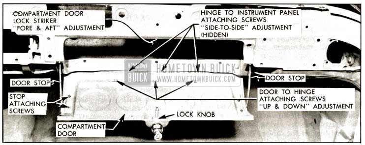
1957 Buick Instrument Panel Compartment Door Parts
Adjustment of Instrument Panel Compartment Door
- The screw holes in the compartment door side of the hinge are elongated to permit “up and down” adjustment of the door. See figure 13-20.
- The screw holes in the instrument panel side of the hinge are elongated to permit “side-to-side” adjustment of the door. See figure 13-20.
- The instrument panel attaching screw holes for the lock striker are elongated to permit “fore and aft” adjustment of the top of the door. See figure 13-20.
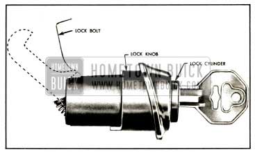
Removal and Installation of Instrument Panel Compartment Door Lock Cylinder
- Note position of lock cylinder key opening when in the locked and unlocked position.
- Insert key in lock cylinder and open door.
- Hold lock bolt in rear position, turn key clockwise 90° from unlocked position, and remove cylinder with key. See figure 13-21.
1957 Buick Instrument Panel Compartment Door Lock Cylinder Removal
Removal and Installation of Instrument Panel Compartment Door Lock Knob
- Open door and remove door lock knob to retainer attaching screw. See figure 13-20.
- Remove lock knob retainer and lock knob.
- To install, reverse removal procedure.
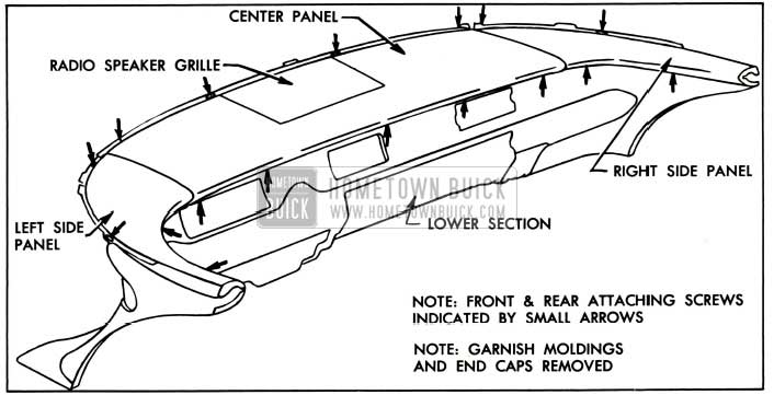
Removal and Installation of Instrument Panel-Upper Section
- Cover front seat.
- Remove windshield side and lower garnish moldings and lower end finishing caps.
- Remove center section by removing attaching screws along front and rear edges of center section. See figure 13-22.
1957 Buick Instrument Panel Upper Section Attachment
Removal of Instrument Panel Cover – Upper and Lower
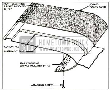
The instrument panel upper section cover consists of a formed plastic and cotton padding. The upper section cover corresponds to the component parts of the instrument panel and is serviced as a three piece unit: a left and right side section and a center section.
The instrument panel lower section cover is made up of a new plastic construction and consists of two parts: one cover attaches to the compartment door and the other part attaches to the lower right side of the instrument panel. When cover option is not used, metal parts are used in place of covers. These metal parts are attached the same as lower section covers. The upper section cover parts are secured to the panel by means of trim cement. The lower section cover parts are fastened to the panel by means of attaching screws.
- Remove upper section of instrument panel and remove radio speaker grille from center section.
- Carefully detach cemented coverings from perimeter of each panel and remove coverings from panels.
CAUTION: Unless required, do not remove cotton or rubber pads from panels. See figure 13-23.
1957 Buick Instrument Panel Upper Cover Installation
- To remove lower cover from compartment door, open door, remove cover attaching screws, and disengage cover attaching tabs.
- To remove lower cover from right side of instrument panel, remove cover attaching screws from back side of instrument panel.
Installation of Instrument Panel Cover-Upper and Lower
- Clean and dry cementing surfaces on each upper section of instrument panel.
- If necessary, repair or replace cotton padding.
- Apply trim cement to cementing surfaces of cover and panel. This include1 application of trim cement to peak lines of covers and corresponding surfaces on panels. Allow cement to dry for several minutes. See figure 13-23.
- Start application of side panel covers by engaging peak line of cover with corresponding cementing surface of side panel. This aligns peak. Work from peak line to edges. Keep peak line straight. Then press cemented surfaces firmly to obtain a good bond. See figure 13-23.
- Position cover on center panel. Line up radio speaker grille opening and peak of cover with panel and press cover material firmly to place. Then align and secure front, rear, and side sections of cover as shown, Install radio speaker grille. See figure 13-23.
- Clean up and install upper sections of instrument panel. Install side sections first. Then install all other parts previously removed.
- To install lower covers, reverse removal procedure.
Leave A Comment
You must be logged in to post a comment.