SECTION 13-G 1957 BUICK ELECTRICAL (ALL SERIES)
13-22 1957 BUICK ELECTRICAL CIRCUIT TROUBLE SHOOTING PROCEDURES (ALL SERIES)
The 1957 Buick electrical circuit is very similar to the circuit used in 1956 bodies. The current for all of the 1957 Buick electrical circuits is provided by a twelve volt battery. The power windows and electric horizontal seat adjuster are actuated by individual twelve volt, reversible direction, series wound motors. The six way tilt type seat adjusters are powered by individual twelve volt reversible direction, shunt wound motors. Each of the electric motors is protected by a circuit breaker designed into the motor case. Other components of the electrical circuit are protected by a circuit breaker installed at the shroud panel.
In addition, the window circuit includes a relay assembly which prevents the operation of the window regulators and seat adjusters unless the ignition switch is turned on. On bodies not equipped with power windows, a relay assembly is not included in the 1957 Buick electrical seat circuit.
A new feature of the electric motors in the 1957 bodies is the use of a newly designed socket and blade type connector which is attached directly to the motor case. The new connector provides a more positive electrical connection and facilitates the connecting of the wire harness leads to the motor leads.
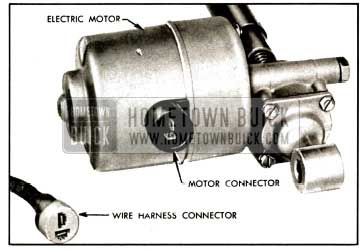
1957 Buick Socket and Blade Type Connector for Seat Motor
1957 Buick Power Window and Horizontal Power Seat Circuits
Failures in a circuit are usually caused by short circuits or open circuits. Open circuits are usually caused by breaks in the wiring, faulty connections, or mechanical failure in a component such as a switch or circuit breaker. Short circuits are usually caused by wires from different components of the circuit contacting one another or by a wire or component grounding to the metal of the body. See figure 13-133 or 134.
- Checking Procedures.
- Checking for current at door window switch.
- Connect light tester to center terminal of switch terminal block.
- Ground light tester ground lead to body metal.
- If tester does not light, there is no current at terminal block.
- Checking door window switch.
- Place #12 jumper wire on switch terminal block between center terminal (feed) and one of two motor wire terminals. If motor operates with jumper wire, but did not operate with switch, switch is defective.
- Checking for current at door window switch.
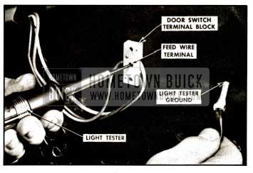
1957 Buick Checking Switch Feed Terminal
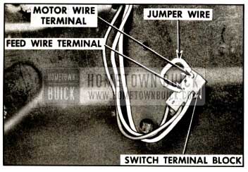
1957 Buick Checking Switch Terminal Block
- Place #12 gauge jumper wire on switch terminal block between center terminal (feed) and terminal of motor wire to be checked.
- Connect light tester to one of the terminals in harness socket as shown.
- Ground light tester ground lead to body metal.
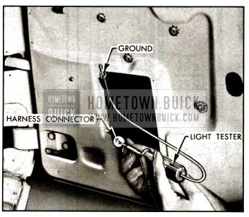
1957 Buick Checking for Current at Harness Connector
- Check ground of motor. Motor is grounded to door inner panel through regulator frame attaching screws.
- Connect one end of a #12 gauge jumper wire to battery positive pole and other end to lowering cycle motor terminal. If motor fails to operate, motor unit is defective or mechanical stoppage exists in window system.
- Disconnect jumper wire from lowering cycle motor lead terminal and connect it to raising cycle motor terminal. If motor fails to operate, motor unit is defective or mechanical stoppage exists in the window system.
- Typical Failures of Power Window and Horizontal Power Seat Circuits.
The following typical conditions and corrections have been listed as an aid for eliminating electrical failures in the electrically powered window regulator and horizontal seat adjusters. The right and left rear door or quarter window circuits are essentially the same as the right front door window circuit; therefore, all references to the right front door window circuit will also apply to the right or left rear door or quarter window circuits. It should be noted that multiple failures in the circuit may lead to a combination of conditions, each of which must be checked separately. See circuit diagram shown in figure 13-133 or 134.
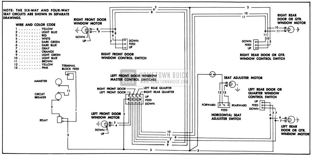
1957 Buick Power Window and Horizontal Power Seat Circuits-Series 40-60
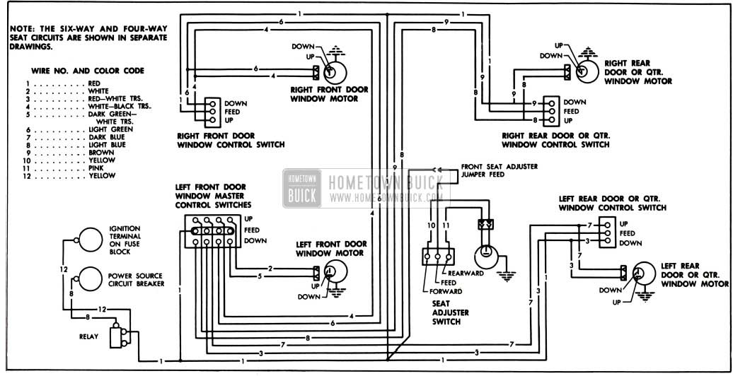
1957 Buick Power Window and Horizontal Power Seat Circuit-Series 50-70
- Right door window will not operate from right door window switch but will operate from master switch. The trouble is located in the circuit between the feed wire terminal of the relay and the right door window motor lead terminals.
- Check feed wire from relay to right door window switch.
- Check operation of right door window switch.
- Check two motor wires from right door window switch to right door window motor leads.
- Right door window will not operate from master switch, but will operate from right door window switch. The left door window will operate from master switch. The trouble is located in the circuit between the feed wire terminal of the master switch and the right door window motor lead terminals.
- Check operation of master switch.
- Check two motor wires from master switch to right door window motor lead terminals.
NOTE: THE SIX-WAY AND FOUII-WAY SEAT CIRCUITS ARE SHOWN IN SEPARATE DRAWINGS.
- Right door window will not operate from master or right door window switches. The left door window operates from master switch. The trouble is located between the feed wire terminals of both switches and right door window motor.
- Check for mechanical stoppage in right door window.
- Check operation of master and right door window switches.
- Check motor wires from master and right door window switches to right door window motor leads.
- Check operation of right door window motor.
- Right and left door windows will not operate from master switch, but right door window will operate from right door window switch. The trouble is located between the feed wire terminal on the relay and the master switch motor wire terminals.
- Check feed wire between relay and master switch.
- Check operation of master switch.
- Left door window will not operate but right door window will operate from master and right door window switch.
The trouble is located between the feed wire terminal on the master switch and the left door window motor.- Check for mechanical stoppage of left door window.
- Check operation of master switch.
- Check motor wires from master switch to left door window motor leads.
- Check operation of left door window motor.
- Horizontal seat regulator will not operate, but door windows operate.
The trouble is located between feed wire terminal of relay and the horizontal regulator motor.- Check for mechanical stoppage of front seat assembly.
- Check feed wire between relay and seat adjuster switch.
- Check operation of seat adjuster switch. (4) Check motor wires from seat adjuster switch to horizontal regulator motor leads.
- Check operation of horizontal regulator motor.
- All electrically powered windows and horizontal seat regulators will not operate.
- Check battery.
- Check wire from ignition switch to relay.
- Check circuit from battery to circuit breaker.
- Check circuit breaker.
- Check wire from circuit breaker to relay.
- Check operation of relay.
- Check feed wire from relay to window and seat adjuster switches.
- Check operation of window and seat adjuster switches.
Six-Way Power Seat Circuits
The power-operated six-way tilt-type seat adjusters are operated by an actuator assembly which consists of a twelve volt reversible type motor with a built-in circuit breaker, a relay, gear box with jack screws and three spinning nut assemblies which include solenoids as shown in the illustrations. The motor assembly is controlled by a three button switch located on the left front seat side panel.
The seat circuit power feed wire is controlled by a relay assembly when the car is equipped with power windows. On these styles the ignition switch has to be turned to the “on” position to operate the seat adjusters.
The seat actuator includes a separate spinning nut assembly with a solenoid for each of the three basic movements of the seat: 1. Up and down front edge, 2. Up and down rear edge, 3. Fore and aft.
When the front button of the seat control switch is pushed up or down, current flows to the “up and down front edge solenoid,” actuating the solenoid and locking the spinning nut out of freewheeling. Simultaneously current flows to one of the motor field coils and to the relay assembly, closing the contacts between the relay power source and the armature motor lead, thereby operating the seat adjuster motor. When either of the other two adjustments is desired and the switch is operated, the affected solenoid is actuated and the motor assembly operates in the _same manner as outlined previously.
Checking Procedures.
It may be necessary to use only one or all of the procedures outlined to locate an electrical failure in the circuit, depending on the nature of the failure. If the location of the failure is evident, follow only the steps outlined to check the affected wire or component. If the location of the failure is not evident, follow the procedure as outlined. Before performing the checking procedures, check the seat adjusters and seat actuator assembly for mechanical failure. In addition, study the seat circuit diagrams located in this section to become familiar with the seat circuit. NOTE: Figure 13-135 shows the seat adjuster power unit with seat trim and springs removed for illustrative purposes only.
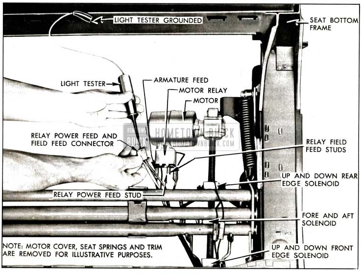
1957 Buick Testing Circuit of Six-Way Seat
- Checking for current at circuit breaker.
- Connect one light tester lead to battery side of circuit breaker and ground other lead. If tester does not light, there is no current at battery side of circuit breaker.
- To check circuit breaker, disconnect switch feed wire from breaker, and with light tester check for current at switch side of circuit breaker. If tester does not light, there is no current flowing through circuit breaker.
- Checking the relay assembly at the shroud.
- With light tester, check for current at circuit breaker side of relay. If tester does not light, there is an open or short circuit between circuit breaker and relay assembly.
- Turn ignition switch on and with light tester check for current at seat control switch side of relay. If tester does not light, the relay is defective or there is a short or open circuit between ignition switch and relay assembly.
- Checking for current at the seat control switch.
- Connect one light tester lead to feed terminal of switch block and ground other tester lead to body metal. See location #1 in figure 13-137.
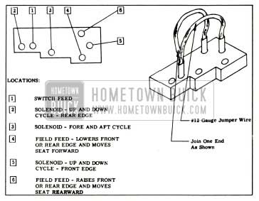
1957 Buick Checking Six-Way Seat Switch Terminal Block
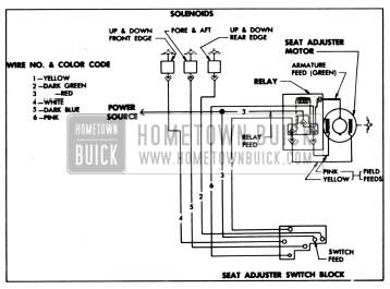
1957 Buick Six-Way Seat Circuit Diagram
CAUTION: To prevent damaging the solenoid, do not energize solenoid with jumper wire for more than one minute.
Three-Way Jumper Wire.
To make jumper wire, obtain two (2) pieces of #12 gauge wire, each 4 1/2″ long. Join one end of each wire as shown in figure 13-137. The joined end can be inserted in the feed location in the switch block; one of the remaining ends can be inserted into one of the field locations in the switch block; the other end can be inserted into one of the solenoid locations. IMPORTANT: To obtain a seat movement using a 3- way jumper wire at the switch block, the switch feed location, one of the motor field wire locations and one of the solenoid locations have to be connected simultaneously.
The switch locations to be connected to obtain a specific seat movement are outlined as follows:
- To raise front edge of seat, place jumper in locations 1, 6 and 5.
- To lower front edge of seat, place jumper in locations 1, 4 and 5.
- To raise rear edge of seat, place jumper in locations 1, 6 and 2.
- To lower rear edge of seat, place jumper in locations 1, 4 and 2.
- To move seat forward, place jumper in locations 1, 4 and 3.
- To move seat rearward, place jumper in locations 1, 6 and 3.
- Typical Failures of Six-Way Power Seat Circuits.
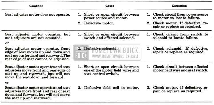
1957 Buick Seat Adjuster Troubleshooting
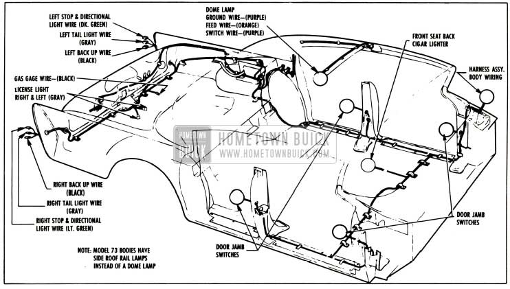
13-23 1957 BUICK BODY WIRING DIAGRAMS (ALL SERIES)
This paragraph contains 1957 Buick wiring circuit diagrams for the various bodies. Where the wiring harness installation is very similar in several different model bodies, only one diagram is shown for these models. Only those diagrams that apply to wiring installed by Fisher Body Division are included; for all other wiring diagrams, refer to Section 10-J of the Buick Chassis Service Manual.
The location or routing of the wiring to any 1957 Buick electrical unit is shown. The 1957 Buick wiring may be easily traced by paying attention to the color code on each wire and the color code on the diagram. Notice also that the location of the hold-down clips and other fasteners is shown. 1957 Buick Wiring diagrams for optional electrical accessories such as power windows or power seats are shown in separate figures.
1957 Buick Body Wiring Circuit Diagram-Series 40-60 Two-Door Closed Bodies
1957 Buick Body Wiring Circuit Diagram-Series 40-60 Four-Door Closed Bodies
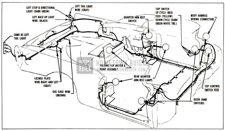
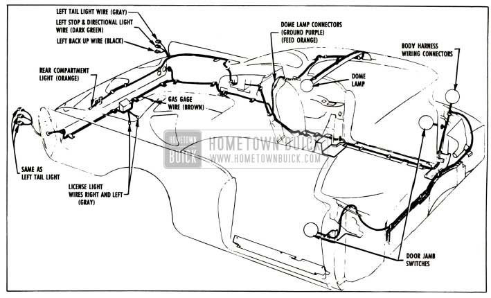
1957 Buick Body Wiring Circuit Diagram-Series 40-60 Convertibles
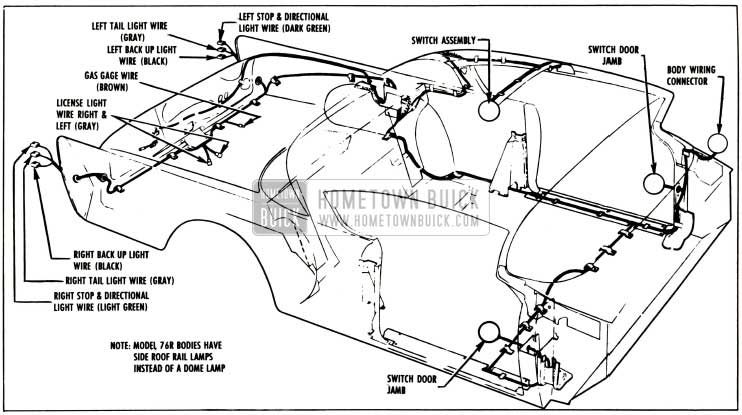
1957 Buick Body Wiring Circuit Diagram-Series 50-70 Two-Door Closed Bodies
1957 Buick Body Wiring Circuit Diagram-Series 50-70 Four-Door Closed Bodies
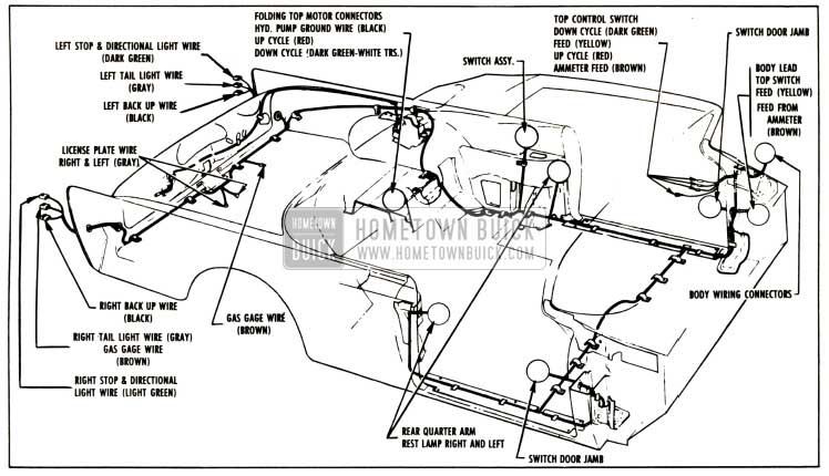
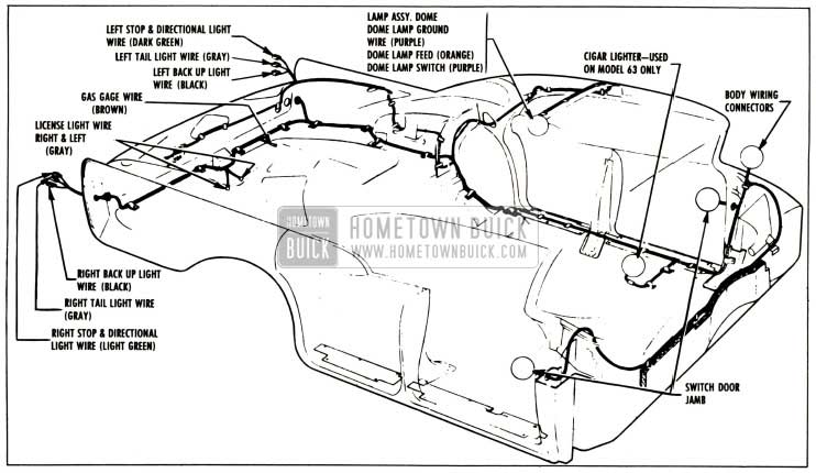
1957 Buick Body Wiring Circuit Diagram-Series 50-70 Convertibles
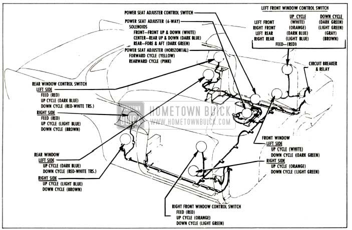
1957 Buick Power Window and Seat Wiring Circuit Diagram-Series 40-60
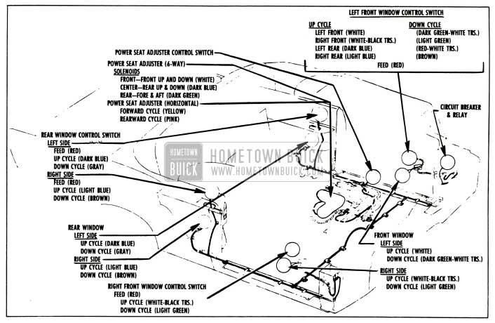
1957 Buick Power Window and Seat Wiring Circuit Diagram-Series 50-70
Leave A Comment
You must be logged in to post a comment.