POWER STEERING GEAR THRUST BEARING ADJUSTMENT
The present thrust bearing adjusting nut Gr. 6.531 Part No. 5664762 will be replaced on 1954 after jobs approximately September 1 by a Belleville Washer and thinner adjusting nut. The new washer and thin nut will simplify the worm adjustment of the gear because the nut needs only to be torqued to 20-30 foot lbs. and backed off 1/4 turn. The Belleville Washer, which is assembled between the upper thrust bearing race and the nut, will automatically give a thrust bearing preload between 1/2 and 3/4 lb. which is the same as the present specification.
Power steering gears equipped with the new Belleville washer and nut may be adjusted in the same manner described in paragraph 8-14, sub paragraph c of the 1954 Shop Manual until such time when a new worm bearing adjusting nut and wrench (to be used with a torque wrench) is released. The new wrench is included in the 1955 essential tool kit.
The Belleville Washer not only makes the initial preload adjustment easier but also maintains the preload over a longer period by compensating for wear. In addition, the washer will reduce the tendency of an out of square face of the adjusting nut to cock the valve spool when assembled and cause scoring and erratic valve spool operation.
To avoid increasing the length of the steering worm shaft when the washer is used, the old nut was replaced by the thin one. Stock of the old nut should be used up without the Belleville Washer otherwise the nut cannot be properly locked in place by staking. When stock of the old nut is used up, all service replacements of the adjusting nut should be made with Kit Gr. 6.531 Part No. 1392113 which consists of a Belleville Washer and a new nut.
STEERING OIL PUMP BELT TENSION
To make certain that the steering oil pump belt has sufficient tension so that it will not slip on the pump pulley during parking, resulting in a lumpy feeling in the steering from erratic power assist, the following procedure should be used:
With a new belt, the pump should be adjusted in the support bracket until the torque applied at the steering pump pulley nut is 40-45 pounds before the pully slips in the belt. With a used belt, the tension should be set so that the torque required to slip the pulley in the belt is only 30-35 pounds.
A new belt requires more tension because it will quickly stretch and lose tension, and the original setting must be sufficiently high so that the belt will still not slip after stretching even though the belt is not retightened. Once a belt starts to slip, it becomes glazed and is very difficult to prevent from slipping even with higher tension. Once a new belt has stretched and the tension is reset it will hold the same tension with very little drop off in several thousand miles.
ADJUSTING WHEEL HEIGHT
ALL 1954 MODELS
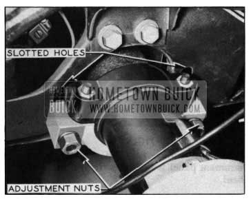
Several requests have been received for information on the procedure used to raise or lower the steering wheel on 1954 models. The height of the steering wheel is adjustable due to elongated vertical slots at the steering column mounting bracket under the instrument panel. See Figure 49.
1954 Buick Adjusting Steering Wheel Height
The following is the correct procedure to raise the steering wheel:
- Disconnect the shift rod from transmission control shaft at lower end of steering column.
- Loosen steering gear to frame mounting bolts.
- Loosen steering column bracket adjustment nuts.
The clearance between the steering column and instrument panel on first production jobs, was 7/16″. An after job change was made on the 40-60-M/100 Series to 11/16″ factory setting.
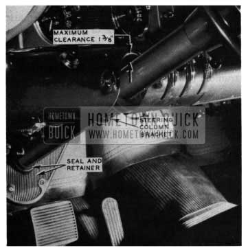
The steering column may be raised as far as adjustment permits. It may be lowered on all Series to the bottom of the slotted holes in the instrument panel, See Figure 49, which will be approximately 1 1/8″ between steering column and instrument panel. See Figure 50.
1954 Buick Steering Wheel Column Bracket
If the steering column is to be lowered more than 1 1/8″, the brackets, see Figure 49, must be inverted 180 degrees so the larger bracket is on top. This will permit the steering column to be lowered further. In any case, the maximum allowable clearance in the lowered position must not exceed 1 3/8″ between instrument panel and steering column to maintain proper adjustment of transmission control linkage.
NOTE: 1/2″ movement of steering column at instrument panel is equivalent to 5/8” at the steering wheel.
When desired wheel position is obtained, tighten steering column bracket adjustment nuts. Tighten steering gear to frame mounting bolts and connect shift rod to transmission control shaft, making sure all rods are properly cotter pinned. Check quadrant alignment per 1954 Buick Shop Manual, Page 5-29, Paragraph 5-12. Then with everything hooked up, check toe-in and correct. (Refer to 1954 Buick Shop Manual, Page 8-4 and 5 Section 8-4.)
NEW POWER STEERING PUMP FRONT SHAFT SEAL
1954 MODEL
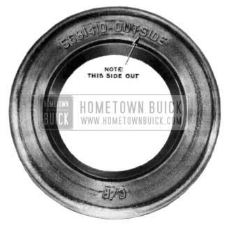
A new hydraulic steering pump front shaft seal made by Chicago Rawhide, Gr. 6.617 Part No. 5681410 has been released as an after- jobs change in 1954, See Figure 51.
1954 Buick Power Steering Pump Front Shaft Seal
The seal which replaces the Vickers Seal No. 5665833 is intended to reduce the number of shaft seal leaks encountered in the past year. A hardened shaft No. 5681681 is required with the new seal because the lip pressure is greater than the previous one. Parts Dept. carries shaft and seal in package Gr. 6.614 Part No. 5681951.
Pumps with the new seal will all have a smaller reservoir and will have a daub of green paint on the front hub of the pump body. At the start of 1954 pumps were 100% air tested for leaks and were identified by a yellow daub of paint in the same location. The green paint will signify the pumps have been air tested and have the latest Chicago Rawhide Seal.
The hardened shaft No. 5681681 will be identified by either a daub of green paint on the threaded end of the shaft or a machined groove on the .75 diameter adjacent to the splined end of the shaft. It is permissible to use the hardened shaft with either the old or new seal, but the old shaft cannot be used with the new seal.
A master service kit No. 5681964 which includes the new seal will be used for service of pumps built after the change. A master service kit No. 5682130 which includes the new shaft and new seal will be used for service of pumps built prior to change. The old master repair kit No. 5665731 which includes the old Vickers seal will be used up on pumps built prior to change.
When the Vickers seal No. 5665833 is used for service of leaking pumps built prior to the change, the following procedure should be used when installing the old type replacement seal:
- Clean the casting bore after the leaking seal is removed and remove any burrs which would allow oil to leak between the 0. D. of the seal and I. D. of the casting bore.
- Check the pump shaft surface that the seal lip contacts to make certain there is no groove on the surface underneath the lip of the seal which would allow the oil to flow out. If shaft replacement is necessary use kit No. 5681951 which can be used for all shaft replacements on pumps before or after the change and which consists of a new shaft and seal.
- Leave the protector sleeve in the seal until ready for installation.
- When ready for installation, remove the protector sleeve from the seal and dip the seal in automatic transmission fluid. Type “A” or Buick Dynaflow Fluid.
- Use instructions for installing the seal as out – lined in the 1954 Shop Manual, page 8-26.
- Press seal into housing bore solidly.
- Immediately install shaft and bearing assembly.
Care should be used to avoid damage to the seal lip by the splined end of the shaft hitting the seal. In event the shaft cannot be assembled immediately the protector sleeve should be installed in the seal with the rounded end of the sleeve toward the inside of the pump.
lt will be noted that when using the above procedure, the seal will be installed in the reverse position from what has been specified previously. This reversal has been made because there is less chance to curl the lip of the seal the wrong direction during shaft assembly and the lip of the seal is less sensitive to dirt and other foreign matter in the oil in the new position. The seal installation still results in the greatest pressure on the seal being from the outside of the pump during operation. The seal reversed still has enough capacity to prevent air from being drawn into the pump and there is less chance for misassembly to cause a leak under static conditions.
STEERING COLUMN RATTLES
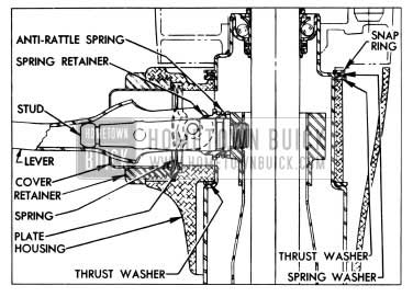
Certain reports would indicate that some steering column rattles are due to the fact that the antirattle spring (See Figure 52)
1954 Buick Steering Column Illustration
on the shift control lever is not heavy enough.
We recently started using a new spring at this position which is considerably stronger than those previously used. The new spring, Gr. 4.036 Part No. 561362, may be installed on any car where shift tube rattles in the steering column are a complaint. This new part is now being used in production and the parts warehouses have stock of the heavier spring for field complaints.
POWER STEERING NOISE
Some complaints of power steering gears having a gurgling or frying noise in the straight ahead position may be traced to a faulty flow control valve in the steering pump, but in most cases it is caused by a restriction due to flash in the 90 degree fitting on the pressure hose. See arrow, Fig. 53.
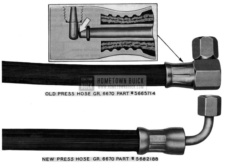
1954 Buick Power Steering Pressure Hose
If noise of this type occurs replace the old pressure hose with the new type Gr. 6.670 Part No. 5682188. See Fig. 53 before attempting any internal repairs to the steering gear or pump. If the new type hose is not immediately available it is suggested that you try a pressure hose from a car that is known to be quiet and OK. Installing a new hose of the old type from stock may not necessarily be the answer to this trouble, because it too could have a restriction in the fitting.
It is important when installing the new hoses. Gr. 6.670 Part No. 5682188 that there isn’t metal to metal contact between the longer fittings on the new hose and the gear housing. The hose should not be twisted when the fittings are tightened but rather should be free to move easily when pump pressure is applied.
Leave A Comment
You must be logged in to post a comment.