1953 POWER BRAKE UNIT REWORK
SPECIAL SERVICE LETTER NO. 137 (REPRINT)
Several very important improvements have been made in the 1954 Power Brake cylinder assemblies which we wish to incorporate in all 1953 Power Brake equipped cars, regardless of mileage, age or owner ship on a campaign basis. To incorporate these changes as quickly as possible and with the minimum of owner inconvenience, the complete Power Brake assembly should be replaced with a new unit now available in limited quantities from your parts warehouse under Group 4901, Part 1163402. Units required for cars tied up should be ordered on a car tie-up order blank.
When ordering units under Part 1163402, 1953 Power Cylinder assemblies containing all the latest changes and improvements will be shipped. If part 1163402 is not available, your warehouse will substitute a 1954 Power Brake assembly, which can be installed on 1953 cars with slightly additional work. All parts necessary to install a 1954 unit on a 1953 car are furnished with the unit, together with complete instructions for making the installation.
In no case should the 1954 assembly be ordered through the Parts Department for this campaign- order only Group 4901 Part 1163402.
The flat rate time for installing a 1953 unit on a 1953 car is 1.6 hours. This time includes the bleeding of the brake system after installation.
Additional time of .8 hours is required to install a 1954 unit on a 1953 car; therefore the time for this operation is 2 .4 hours for the complete job.
It is important that the following marking procedure be carried out on every car campaigned.
After an installation is completed, paint a white X on the access cover on the left side of the cowl. This access cover is the plate which mounts the windshield wiper jar. Painting the X on every job campaigned will indicate to anyone who raises the hood that the brake power cylinder has been replaced with the latest type unit.
We suggest that each dealer immediately make up a list of the 1953 Power Brake jobs sold showing the owner’s name, address and car serial number. The list should also provide a column for inserting the date the unit was replaced.
Also please tag and carefully pack all replaced cylinders and forward to your zone M.R. room promptly. You may list more than one serial number on an A.F.A.; in such cases the serial numbers, model, part number and R .0. number must be listed in the body of the A.F.A.
No time limit has been established for the completion of this campaign; however, it is extremely important that it be concluded at the earliest possible date. The starting date for this campaign was January 25, 1954.
POWER BRAKE RESERVOIR LOW ON FLUID
Some cases of power brake reservoirs being low on fluid after bleeding the system with a pressure type bleeder have been reported. In some cases the fluid level was 1 3/4″ below the top of the reservoir (approximately 1 1/4″ below the threaded portion). It appears that the reason for the low level after bleeding is that since the air in the reservoir has no means of escape, it remains there and prevents the fluid from rising. Should a reservoir be left partly filled, the next examination would erroneously indicate a possible leak.
To prevent needless replacement of power brake assemblies as leakers, we advise whenever power brakes are bled in the manner described above , that the fluid level be checked and if necessary the reservoir be filled to the proper level after such bleeding, to be sure that the fluid is at the proper height in the reservoir.
POWER BRAKE VACUUM PUMP LUBRICATION
1954 MODELS
The oil level in the reservoir of the power brake vacuum pump should be checked every 1000 miles. (The former recommendation was at 5000 mile intervals.) This is done by removing the filler screw on the top of the pump, which is located on the left front gravel shield. Fill to top of the cover regardless of make of pump.
Use power brake cylinder oil Gr. 4.898 Part No. 1165078 (3 oz. can) in servicing the vacuum pump.
CAUTION: On service installation of vacuum pump, check oil level -in pump reservoir and service as recommended above before installation.
The above correction should be made in the 1954 Shop Manual, Page 9-32 Subparagraph 9-18 (a).
BRAKE FLUID IN POWER BRAKE SYSTEM
ALL POWER BRAKE JOBS
Inquiries have been received as to the quantity of brake fluid that is used when replacing a power brake cylinder assembly. Engineering states that it takes .9 of a pint to fill a completely dry power brake system. We have found that it takes approximately one pint to bleed the system as covered in the 1953 Shop Manual, par. 8-4, page 172. For practical purposes, it would be reasonable to say that one quart of brake fluid would be used whenever a power brake cylinder assembly is replaced or overhauled.
BRAKE FLUID APPROVAL
STATE OF MINNESOTA
A new law was enacted in the state of Minnesota which governed the use and sale of Hydraulic Brake Fluids.
This law prohibits the sale of brake fluid unless it is an approved fluid conforming to or exceeding SAE Specification No. 70R 1.
The Delco Brake Fluid or Heavy Duty Super 11 carried in Buick Warehouses under Gr. 4.683 has been tested and approved by the Minnesota State Highway Department.
ELECTRIC VACUUM BOOSTER PUMPS GROUNDED
There were approximately 300 moraine vacuum booster pumps installed at both Atlanta and South Gate and a small quantity at Flint which had the electric motor internally grounded.
Normally, the booster pump motor will run when the ignition is turned on, but will stop running as soon as the engine is started. When the pump motor is grounded internally, it will not stop running when the engine is started, providing the hand brake cable or the speedometer cable comes in contact with the motor case.
When complaints are received that the booster pump motor is running at times when the engine is running, it can be checked by starting the engine and purposely touching the parking brake cable to pump frame. If pump motor starts and stops, the motor is internally grounded and should be corrected as outlined below.
Pump motors which incorporate a thermal circuit breaker and are grounded internally have yellow tape on one lead. Motors which are equipped with a thermal circuit breaker and are not grounded internally have white tape on one motor lead. The following corrective measures are recommended:
40-60 SERIES
Split a 9 1/2″ length of 7/32″ I.D. (windshield washer) hose and install on speedometer cable 1″ below fender skirt clip that holds cable to fender skirt. Hose should be taped securely in place, with Minnesota Mining Electrical Scotch Tape at each end and near center of hose. (See Fig. 54).
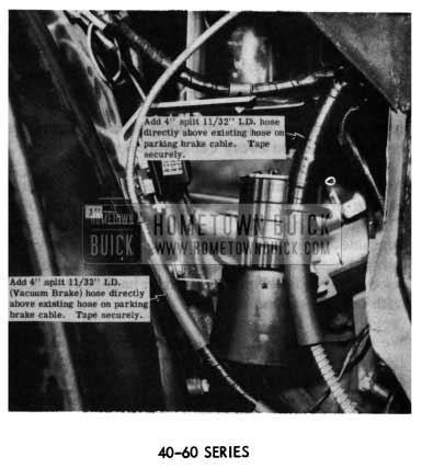
1954 Buick Electronic Vacuum Booster Pumps – Series 40-60
Also, install a 4″ length of split 11/32″ I.D. (vacuum brake) hose directly above hose already installed on hand brake cable. The hose should also be securely taped in place.
50-70 SERIES
Install a 12″ length of split 11/32″ I.D. (vacuum brake) hose on hand brake cable 4″ below point where cable comes through dash into engine compartment. Tape securely at both ends of hose and use a generous amount of tape at the point where cable comes closest to vacuum pump. (See Fig. 55).
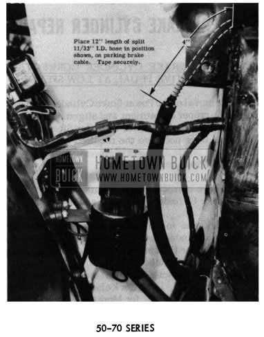
1954 Buick Electronic Vacuum Booster Pumps – Series 50-70
VACUUM BRAKE BOOSTER
PUMPS FAILURE
There have been some reports of the electric vacuum booster pump on power brake equipped cars failing due to water entering the drive motor. Water can enter these motors through holes pro vided for the wires.
When power brake equipped cars are serviced, a small amount of Permagum should be installed over the wire openings in the motor to prevent water entry.
Permagum is a soft putty-like substance (thumbing compound) which can be applied with a putty knife or high pressure gun. It is non-shrinking or sticky to touch, and is available through Minnesota Mining Company under No. EC1279. Minnesota Mining has two similar materials called “Scotch Calk” and “3M Body Caulking” which are basically the same as EC1279. These are available in smaller tubes which are more easily handled in dealerships.
CAUTION: Do not use a substitute material as it may soften with heat and flow into the pump motor.
RIGHT FRONT BRAKE PIPE INTERFERENCE
We are still receiving a number of complaints in which an interference condition exists between the right front brake pipe and the back of the front suspension upper control arm (rear leg) on top of the front frame cross member. If the brake pipe is not down flat against the cross member and firmly in the clip located ahead of center on top of the cross member, it should be bent down and in toward center of car and installed in clip. Clearance between brake pipe and any portion of the upper control arm should be at least 1/4″ or better.
After above correction has been followed, hold a mirror in front of the cross member adjacent to brake pipe to determine that sufficient clearance has been obtained.
CAUTION: The use of copper tubing when re placing a damaged brake pipe is not recommended as a permanent installation because crystallization of the pipe will result in ultimate brake failure.
NOTE: Care must be exercised when lubricating the right control arm fitting to prevent bending or distorting the brake pipe by prying with the nozzle of the gun.
All service department personnel, (Lubricare Technicians, mechanics, New Car Service personnel, etc.) should check and correct this condition on all 1954 models, including prior deliveries.
POWER BRAKE BOOSTER IDENTIFICATION
SUBMITTING PRODUCT REPORTS AND AFA’S
Inasmuch as two types of power brake boosters are used in production, it is requested that when sub mitting Product Reports or AFA’s on this item you state the make or the name of the manufacturer. One is manufactured by Moraine “Products Division under the trade name “Morvac” which is stamped on the top plate. The other is manufactured by Trico Products Corporation and the name “Trico” is stenciled on the side of the unit.
NEW POWER BRAKE CYLINDER PLUG
1954 MODELS
To prevent the possibility of damaging the “0” ring seal on the power brake cylinder plug in production, a new plug is going into production about March 1, 1954.
This plug canberemovedwithaNo.482 “Williams” adjustable face spanner or a suitable tool can be made from the dimensions shown in Fig. 56.
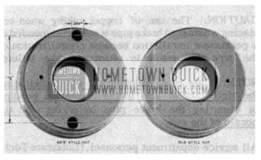
1954 Buick Power Brake Cylinder Plug
The old type plug is interchangeable with the new plug; however, extra care must be taken when in stalling the “0” ring seal to prevent it from slipping off and being cut when assembling the hydraulic cylinder.
POWER BRAKE VACUUM PUMP MOTORS BURNING
1954 MODEL
It has been called to our attention that the electric motors in the power brake vacuum pumps in many cases are being burned up due to the fact that they are left running while repairs are made on other portions of the car. It is therefore recommended that when the ignition is “on” and the engine is not running, such as would be the case if power seat or window repairs are being made, that the fuse be removed from the line to the power brake pump. This is recommended whenever it is anticipated that the ignition switch will be left on for periods longer than ten minutes.
POWER BRAKE CYLINDER REPAIR
1954 POWER BRAKE CYLINDER CORRECTION FOR SENSITIVE PEDAL AT LOW SPEEDS
Before removal of the Power Brake Cylinder from car, check for proper adjustment and alignment of Power Cylinder Push Rod in Power Cylinder Sleeve. If the Push Rod does not have the required 1/16″ lash or if touching inside diameter of Power Cylinder Sleeve correct and road test.
If the above correction has no effect, then remove Power Brake Cylinder and repair as follows:
(1) Check the manufacturing date of the Power Brake Cylinder Assembly stamped on the bottom of Cylinder Housing for Kelsey-Hayes unit and metal tag attached to Front Flange Bolt on Moraine Products unit, and if manufactured prior to February 1, 1954, for Kelsey-Hayes units and February 25, 1954, for Moraine Products units, then overhaul Power Brake Cylinder Assembly using Service Repair Kit Gr. 4.898 Part No. 1392062 as follows:
1 5454861 Seal, Primary Cup
1 5454860 Cup, Primary
1 5454842 “O” Ring-Cyl. Housing
1 5454863 Cup, Reaction Piston
1 5454850 Reaction Piston Ass’y
1 5454802 “O” Ring, Reaction Rod (Packaged for Service)
1 137127 Pin, Cotter
1 1167395 Spring, Reaction Rod (New)
1 1162887 “O” Ring (Power Piston to Guide)
1 1163518 “O” Ring (Air Valve Seat) (Packaged for Service)
1 1165078 Oil, Power brake cylinder
1 1162896 Gasket, Inspection Screw
1 5454821 Seal, Head Housing
- Clamp Power Brake Cylinder vertically in vise and remove Head and Air Cleaner Assembly by removing four (4) 7/16 bolts. Do not disassembly Head and Air Cleaner Assembly.
- Remove Power Piston Guide and Sleeve Assembly from Cylinder Housing. Make thin flexible metal band approximately 1 1/2″ to 2″ wide to tightly clamp around leather Piston Cup, and by bending ends of metal band to clamp and support Piston Assembly in vise, remove Piston Guide and Sleeve Assembly from Piston and Guide Assembly by removing 3 7/16 bolts.
- Leave Piston and Guide Assembly in vise for reassembly after replacement of Reaction Rod “O” Ring, Spring, Reaction Piston Assembly, Air Valve “O” Ring, and Reaction Piston Cup in Piston Guide and Sleeve Assembly.
- Install new “O” Ring (Power Piston to Guide) in Power Piston and Guide Assembly before reassembly of complete Piston Assembly.
NOTE: During disassembly and reassembly of Power Piston and Guide Assembly, use extreme care in preventing brake fluid or dirt from getting on assembly.
NOTE: Before reassembly of Reaction Rod in Power Piston Sleeve, remove all burrs from cotter pin hole in end of Reaction Rod. Caution: Use fine emery cloth to remove burrs but do not use beyond 1/4- of cotter pin hole on Reaction Rod.
NOTE: After Power Brake Cylinder has been reassembled, clamp vertically in vise and using 3 oz. can of Power Brake Cylinder Oil Gr. 4.898 Part No. 1165078 in Repair Kit, remove inspection hole screw and pour in 1/2 of the can of oil. Use remainder of oil for servicing of the Electro-Vac Power Brake Pump by removing screw on top of the Pump and fill to top of the cover.
NOTE: Flat Rate Time for operation under section
- is 3.1 hrs. Same as operation 581 and 581-1.
- If the Power Brake Cylinder was manufactured after the dates as listed in above, repair the Power Brake Cylinder as follows:
- Remove Cylinder Housing Assembly from Master Cylinder Assembly by removing four (4) 5/16 – 24 Nuts and carefully lift the Housing Assembly vertically from the Master Cylinder to prevent lubricating oil in Housing Assembly from getting on the cups and seals in the Master Cylinder Assembly.
- Remove “O” Ring (Cylinder Housing to Master Cylinder) and destroy.
- Remove the Cotter Pin from end of Reaction Rod and remove Reaction Rod Spring and Spring Retainer. Scrap Cotter Pin and Spring.
- Install new Reaction Rod Spring No.1167395, SeeFigure57, and new Cotter Pin (1/16 x 5/16).
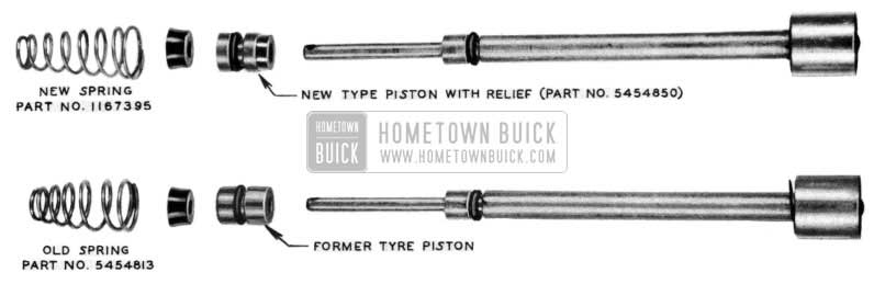
1954 Buick Power Brake Reaction Rod Spring
NOTE: When installing “O” Ring on Cylinder Plug, be sure that it is not twisted and is fully seated against Master Cylinder.
NOTE: Before tightening the four (4) 5/16 – 24 Nuts, push Power Piston and Guide Assembly into fully applied position, then tighten nuts evenly. After complete assembly, the Power Piston and Guide Assembly must return freely to off position.
Flat Rate Time Section (2) is 1.9 hr.
POWER BRAKE VACUUM PUMP
1954 RELAY SPECIFICATION
We have received numerous requests for the electrical specifications on the relay used in the wiring circuit of the Buick power brake vacuum pump.
These specifications are covered on page 9-32, Par. C of the 1954 Shop Manual and they are as follows:
Point Opening .017″ to .033″
Opening Voltage 5.7 to 7.2
After excitation of 12 to 15 volts, points must reclose at not more than 3 volts.
POWER BRAKE VACUUM PUMP INSTALLATION CORRECTION
The installation instructions for the power brake vacuum pump were given on page 188 of BPS Bulletin No. 2.353, dated October 15, 1953. A Flat Rate time of 1.0 hr. was given for this operation on page 208 of BPS Bulletin No. 2.355 dated November 16, 1953.
Due to the difficulty experienced by mechanics, caused by the very limited area in which to work while installing the pump as outlined in BPS Bulletin No. 2.353, it was found advisable to change the procedure.
It is now recommended that the left front wheel and the starter splash pan be removed thereby providing more room in which to work, and that the ignition theft plate be removed to facilitate installation of the electrical lead.
The Flat Rate time for this installation is hereby increased. Please mark your books accordingly. “Operation No. S-9, 1.5 hrs.”
Leave A Comment
You must be logged in to post a comment.