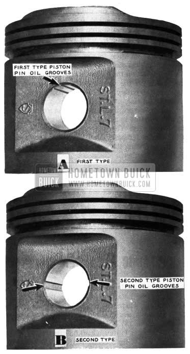
NEW TYPE PISTON
A new type piston has recently gone into production with relocated oil grooves in the piston pin holes.
The first type piston, with four oil grooves in the piston pin hole is shown in” A” Figure l. The second type, piston, with two larger machined oil grooves (180 degrees opposite each other) is shown in “B” Figure 1.
1954 Buick New Piston Type
The second type piston with the larger oil grooves will be furnished by the Parts Department as soon as stock of first type piston is exhausted.
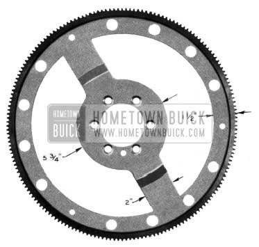
ENGINE OIL LEAKS
When difficulty is encountered in locating oil leaks at rear end of engine, a cutaway flywheel may be installed to provide a window through which the rear main bearing and oil gallery plugs may be observed while engine is running. (Do not run engine over 1750 rpm with a cut-away flywheel attached)
A flywheel may be reworked by cutting out sheet metal stock as indicated in Figure 2.
1954 Buick Flywheel
A minimum of 1/8″ stock should exist between each balance hole and cut line. As a safety precaution, it is suggested that the ring gear be painted yellow inasmuch as an unpainted one cannot be seen while the engine is running.
NOTE: Care must be exercised not to bend or warp the flywheel when cutting.
The above information is offered as a suggestion to be used when oil leaks are extremely difficult to locate, and usual or standard methods have been tried.
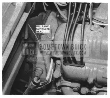
OIL PRESSURE GAGE LINE CORRECTION
(1954 ALL SERIES)
Some difficulty has been encountered on 1954 models in that the loop in the oil pressure gage line makes contact at the rear of the right cylinder head causing it to wear through and leak. See Figure 3.
1954 Buick Oil Line
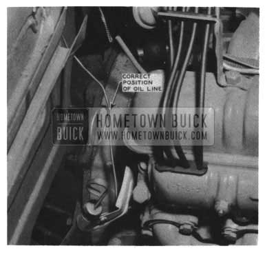
If contact does exist at this point, it will be necessary to rotate the loop 90 degrees or parallel with the dash to obtain clearance. See Figure 4.
1954 Buick Correct Position of Oil Line
1954 CRANKCASE REPLACEMENT FOR 1953
The 1954 cylinder crankcase will be used for the replacement cylinder crankcase on the 1953 Models, after the 1953 stock is exhausted. The 1954 cars do not include the timing hole as used in 1953, therefore, it will be necessary to make provisions for timing the engine after the substitution is made.
The timing mark is to be transferred from the fly wheel to the harmonic balancer or crankshaft pulley whichever the case may be. The procedure for making the timing mark change is as follows:
Before disassembling the old engine, install the 1954 timing indicator bracket (Group 0.219 Part No. 1165764) on the old engine in the same location as on the 1954 engines. Then rotate the crankshaft slowly until the timing mark on the flywheel is in the correct location in the timing hole. With the timing mark on the flywheel in the correct position, make a mark on the pulley that will correspond with the mark on the timing indicator bracket. Then remove the pulley, and with a file make a small groove, similar to the 1954 timing mark, where the pulley was originally marked. Put a small amount of bright paint in the groove so that the mark may be seen easily. The old engine can now be disassembled and reassembled with the new cylinder crankcase, using the marked pulley and the timing indicator bracket.
The 1954 harmonic balancers and flywheels are not interchangeable with the 1953 on the 1953 crankshaft, therefore, do not use a 1954 balancer in place of marking the old balancer or pulley as described above.
Flat Rate time for performing the change will be .3 hr.
HARMONIC BALANCER CHANGED
Approximately May 1st, the method of assembling the harmonic balancer was changed in production. The pulley, which was retained by six (6) pins and three (3) bolts, was changed so that it is now retained by only three (3) bolts. Parts Department advises that the present Pulley, Gr. 0.659 Part No. 1318811J will remain OK for service until stock is exhausted, at which time it will be replaced by the new one. When stock of Balancer assembly, Gr. 0.659 Part No. 1391869, is exhausted it too will be replaced by a new part which is less the pulley. See Figure 5.
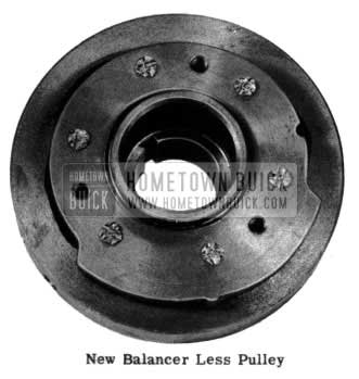
1954 Buick New Balancer Less Pulley
NOTE: When using the balancer, it will be necessary to install the pulley separately. This change will also affect the 1953 balancer and the method of attaching additional pulleys for driving accessories by the use of spacers, pulleys, and longer bolts will remain the same.
ROCKER ARM SHAFT SIZES REDUCED
In Special Service Letter, Dealer No. 135 dated December 28, 1953, and in BPS 2.359 dated January 15, 1954, we outlined a method of grooving rocker arms to provide more oil to the valve sterns where noisy valves were a complaint. In most cases this correction was performed a little too severely and resulted in increased oil consumption.
Effective immediately, the above correction is to be cancelled and not applied to any more engines.
We have reduced the diameter of the rocker arm shaft which, in effect, provides more metered oil through the rocker arms to the valve stems. This method has not increased oil consumption tendencies of the engine.
All Warehouse stock of rocker arm shafts are of the new diameter which is .001″ less than the former shafts. The original limits on the shaft diameter were .810″ to .811″. The limits on the new shafts are .809″ to .810″.
EXCESSIVE OIL CONSUMPTION
Reworking the oil filler caps on air conditioned cars to eliminate excessive oil consumption has not proven entirely satisfactory in all cases. Therefore, a new filler tube extension Figure 6 is being released for service under Gr. 1.768 Part No. 1168039.
All air conditioned cars that had the filler caps reworked as outlined in BPS 2.366 should be re placed with the new type filler tube extension using a regular type filler cap. See Figure 6.
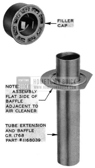
1954 Buick New Filler Tube Extension
V-8 ENGINE BELL HOUSING DOWEL PIN HOLE REAMER
It has been found that reamer, J-2548-3, does not work satisfactorily for realignment of the bell housing to the V-8 engine as covered in paragraph 4-6, step 13 on page 4-14 of the 1953 Buick Shop Manual, and paragraph 5-16, step 11 on page 5-42 of the 1954 Buick Shop Manual.
The dowel pin holes in the V-8 block are not drilled through as in the straight 8 block. Therefore, the present reamer, J-2548-3, which has a taper that extends back from the top 1/2 inch, bottoms in the hole and does not ream the hole deep enough for the dowels. To overcome this, a new reamer, J-4710-6, has been developed that does not have a taper and will, therefore, ream the hole to its full depth. However, because it does not have a taper, it cannot be used by itself as it will not enter into an unreamed hole. Therefore, first ream the dowel, pin holes in the V-8 block with reamer, J-2548-3, as explained in the Buick Shop Manuals. Be sure to bottom reamer, J-2548-3, in the block. Next ream the holes with the new reamer, J-4710-6, making sure to bottom this reamer in the block. The new reamer, J-4710-6 will follow the hole reamed by J-2548-3, however, because its end is square it will clean up that portion of the hole in the block that was left tapered by reamer, J-2548-3.
The new reamer, J-4710-6, may be ordered from Kent-Moore and is priced at $2.50.
ENGINE BREAK-IN OIL
1954
We have been informed that some dealers are draining the factory engine oil prior to new car delivery. We are opposed to this practice because the factory oil has certain characteristics which may or may not be present in the replacement oil which the dealer installs.
In order to obtain the best piston ring break-in, the factory oil should be left in the engine for the first 1000 miles of operation. This is an Engineering recommendation. Please act accordingly.
EXCESSIVE OIL CONSUMPTION
IMPROPERLY INSTALLED ROCKER ARM SHAFT
A few cases of excessive oil consumption had been reported due to the rocker arm shaft on either the right or left bank being installed 180 degrees off in production. This allows the oil to be pumped directly out the rocker arm into the engine around the in take valves. It is suggested whenever excessive oil consumption complaints are reported to first check the rocker arm shafts for proper installation before attempting any major repair. The notch on one end of the rocker arm shaft must be upward in line with bolt heads. See Figure 7.
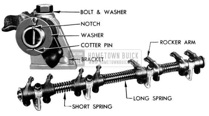
1954 Buick Rocker Arm Shaft
This places the oil holes on the lower side of the shaft in proper relationship to the rocker arms.
CRANKSHAFT CHANGE
V-8 ENGINES
In the past, on the V-8 engine, the Dynaflow Crank shaft was used in all engines and when a Synchromesh Transmission was required, a Pilot Bearing Adapter was used to support the Synchromesh Pilot Bearing in the end of the crankshaft. Production is now using two crankshafts so that the Synchromesh Pilot Bearing is inserted directly in the crankshaft, thus eliminating the bearing adapter on Synchromesh jobs. However, the Parts Department will only service the Dynaflow Crankshaft and when a replacement is required on a Synchromesh job, it will be necessary to order and install Group 0.649, Part No. 1161771 Bearing and Adapter in the crankshaft.
MIXED OVERSIZED PISTONS IN V-8 ENGINES
Some questions have arisen as to the advisability of installing a mixture of oversized pistons in the same V-8 engine as practiced in the Straight 8 engines. This situation usually occurs when only one or a few of the engine cylinders need refinishing, thereby requiring 1he use of oversized pistons in them.
As stated in the 1953 Buick Shop Manual, Page 49, Gr. 2-35, Paragraph d, “it will not be necessary to rebore all cylinders to the same oversize in order to maintain engine balance, since all oversize service pistons are held to the same weights as standard size pistons. If conditions justify replacement of all pistons, however, all new pistons should be the same nominal size.”
DISCONTINUATION OF CAST IRON PISTON
1951 40-50 SERIES
The Parts Department stock of the standard size Cast Iron Piston Group 0.629, Part No. 1390670, used on the 1951-40-50 Series cars, is now exhausted and has been discontinued. If an occasion arises where a standard piston is required for replacements, it will be necessary to use Group 0.629, Part No.3191671 (.005 oversize) or Group 0.629, Part No. 1391672 (.010 oversize) by reboring the cylinder. If a complete set of new pistons are required, the aluminum pistons used during 1951 can be installed, but only as a complete set, as they cannot be used interchangeably if only one piston is required.
ENGINE IDENTIFICATION
As in previous years, the Buick engine will be identified as to series by the suffix numeral stamped after the engine number. Following are the identifying numbers:
“4” Series 40 (Special)
“5” Series 50 (Super)
“6” Series 60 (Century)
“7” Series 70 (Roadmaster)
“7” Model 100 (Skylark)
From the outside appearance, the Series 40 (Special) V-8 engine will appear identical to the Series 50 (Super). However, aside from the two barrel carburetor which identifies the engine as either Series 40 or 50, the 1954 Series 40 engine can be definitely identified by the cast iron fan driving pulley and, as mentioned previously, the engine number with the suffix “4” and a vertical groove 3/8″ x 1/8″ deep cast into the engine serial number pad approximately 1 1/4″ to the rear of the pad centerline.
Series 50 engines will differ in outward appearance from the Series 60 (Century), 70 (Roadmaster) and Model 100 (Skylark) engines since the 50 Series engine will be equipped with a two barrel carburetor and the Series 60, 70 and Model 100 with a four barrel carburetor.
Because of the similarity in appearance of the 1954 engines, and their parts, several methods of identification have been incorporated.
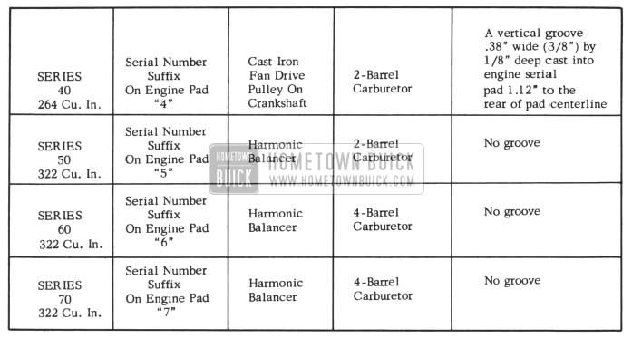
1954 Buick Engine and Carburetor Identification
The chart, Figure 8 lists the identifying points of the engines by Series as they appear in the chassis.
THE NEW SERIES 40 V-8 ENGINES
The Series 40 V-8 engines have a bore size of 3.625 inches, a stroke of 3.2 inches and a piston displacement of 264 cubic inches.
The engines used with the Synchromesh transmissions are equipped with cast iron flywheels for clutch application and have a compression ratio of 7.2 to 1.
The engines used with Dynaflow transmissions are equipped with steel flywheels for torque converter application and have a compression ratio of 8.1 to 1.
Compression ratio is determined by the height of the piston dome in Series 40 engines. The higher compression engine (Dynaflow 8.1 to 1) has a piston dome height approximately .349″ above the top shoulder of the piston whereas the lower compression engine (Synchromesh 7 .2 to 1) has a piston dome height of .243″, the difference being .106″.
The low compression piston can be identified by raised letters “L.C.” (Low Compression) on the top shoulder of the piston on valve side.
All 40 Series engines have cylinder head gaskets .015″ thick.
CAMSHAFT
The camshaft for Series 40 engines will have a groove .060″ wide cut into the ground and just forward of the number 3 bearing journal and the Series 60-50-70 camshaft will have a smooth land surface at this point as shown in Fig. 9.
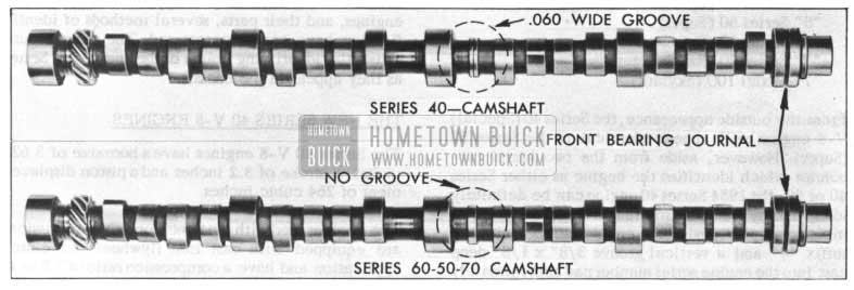
1954 Buick Camshaft Comparison
There is no interchangeability between the 40 Series engine and the 322 cubic inch 50, 60, and 70 Series engines camshafts.
Leave A Comment
You must be logged in to post a comment.