CARBURETOR SPECIFICATIONS
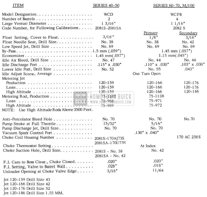
1954 Buick Carburetor Specifications
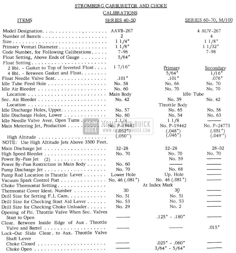
1954 Buick Carburetor Specification
CARTER CARBURETOR CHANGE
1954 LOW SPEED BUCK ON SYNCHROMESH CARS
The best correction for this condition is to install a Carter Carburetor instead of Stromberg and make sure that the Carter has No. 75-1107 metering rods in it. A few early Carters were built with No. 75-994 rods and they do not work as well. Whenever possible the change should be made with Dynaflow equipped cars to affect the above change.
A kit will be available to further improve the performance of the two barrel Carter. Effective with Serial V-398711, all 1954 Series Synchromesh cars will be equipped with Carter Carburetors only. To improve choke operation of the Carter Carburetor during warm-up the choke suction hole has been changed from No. 38 drill to No. 42 on Dynaflow jobs.
For proper identification the first type carburetor tags attached to the carburetor are embossed “2081-S “and second type tags will read” 2081-SA “.
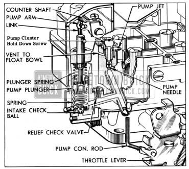
CARTER CARBURETOR PUMP PLUNGER CHANGE
CARTER CARBURETOR BUICK PARTNO. 1163695 1954 SERIES 60-70
Difficulty has been encountered with some early Carter four barrel carburetors built with tag identifications of 2082S L3, 2082S M3, 2082S A4. 2082S B4 and 2082S C4 in that the Acceleration Pump Plunger Leather has become turned back in use. This becomes evident when the throttle resists movement to wide open position and faulty operation due to lack of gasoline from the pump results.
If the pump stroke is made longer than specified, as was the case in the early production carburetors, the leather will come up into the overflow slot in the pump cylinder when the throttle is at idle position. As the throttle is opened the lip of the leather catches in the slot and is turned back causing the above mentioned troubles.
This condition can be corrected by installation of a new pump plunger assembly together with a readjustment of the pump stroke and qualification of the metering rods as shown in the 1954 Buick Shop Manual Section 3-41 and 3-42. It is important that readjustment of the pump stroke be made since replacement of the pump plunger alone may result in a recurrence of the trouble.
It is suggested also that the Acceleration Pump Cluster Hold Down Screw be reworked as shown in Figure 10.
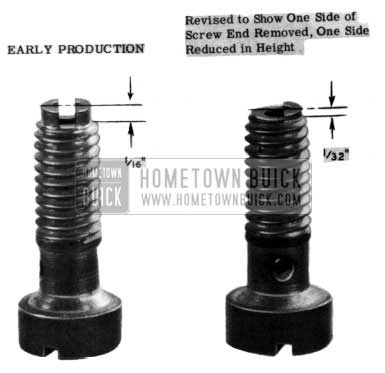
1954 Buick Acceleration Pump Cluster Hold Down Screw
This step is necessary to assure that the pump needle can stroke sufficiently to allow full discharge of the pump. See Figure 11.
1954 Buick Carter Carburetor Cold Stumble
CARTER CARBURETOR COLD STUMBLE
CARTER CARBURETOR BUICK PART NO. 1163692 1954 SERIES 40-50
Some difficulty has been encountered with a few Carter two barrel carburetors No. 2081S when installed on 40 and 50 series synchromesh cars in that a loading condition occurs when accelerations are made during early warm-up. The rich mixture resulting from this condition causes in part the “rhythmic jerk” found in the job when accelerations are made with a cold engine.
The troubles described can be alleviated by following the procedure listed as follows: (Operations can be performed without removing carburetor from cars)
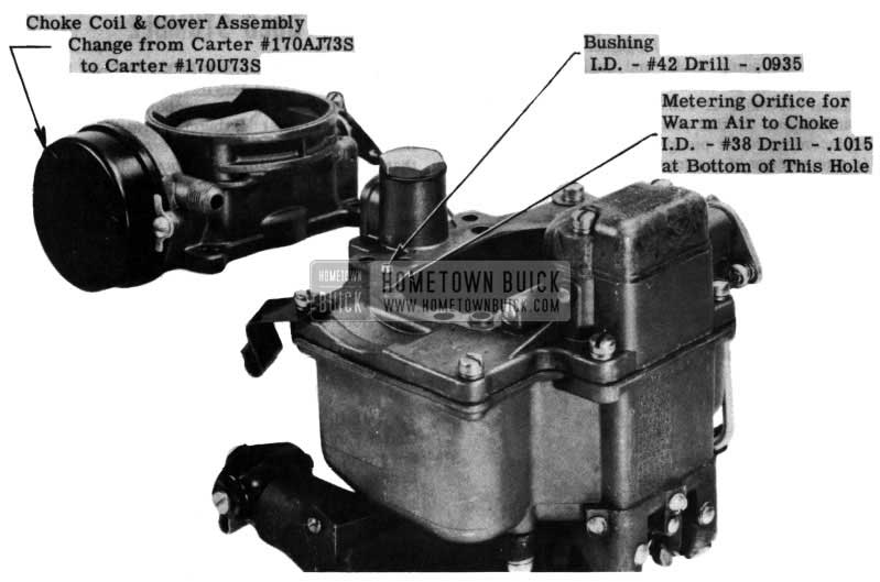
- Remove Choke Coil and Cover Assembly – Carter Part No. 170AJ73S (Shown on Cover).
- Install Choke Coil and Cover Assembly – Carter Part No. 170U73S, using a new cover gasket. Set cover at Index (see 1954 Buick Shop Manual Section 3-7, Figure 3-7).
- Remove Air Horn Assembly and Gasket.
- Install Reducer Bushing (I.D. – No. 42 Drill .0935) in hole which appears in top of bowl cover above metering orifice for choice warm air. See Fig. 12.
1954 Buick Stromberg Carburetor Thermostat
Using a square end tool, drive bushing into hole in air 1-.orn until top of bushing and upper surface of air horn is flush.
- Reinstall air horn assembly using a new gasket. Carter two barrel carburetors having tags stamped 2081SA do not require these changes.
All parts necessary for this operation are released in kit, Gr. 3.783 Part No. 1392064. The kit includes the bushing, thermostatic spring and housing, cover gasket, and new brass tag.
Carter distributors will make this change free of charge if car or carburetor is delivered to them.
If conversion is made in Dealership, the old thermostat spring and housing assembly must be returned to your zone office with the AFA. AFA’s will be accepted for material and labor for any mileage through August 31, 1954.
Flat rate time allowance is .4 hrs.
Because of the few cases reported, this is not a campaign item.
STROMBERG 2 & 4 BARREL CARBURETOR THERMOSTAT & METERING JET CHANGE
1953 – 50 & 70
Some trouble has been experienced with the two and four barrel Stromberg Carburetors in connection with poor cold starting and warm-up characteristics.
The cold start condition is easily identified by excessive engine cranking time before engine operation. The warm-up condition is recognized by excessive engine stalling on stops and poor engine acceleration (stumbling) during engine warm-up period.
The following carburetor modifications and rework are suggested for correcting these aforementioned conditions.
Rework kits have been made available through the Buick Parts Department. These kits will contain the items necessary for the rework (except a special length No. 42 drill used in the four barrel rework – See Step 4 of the four barrel rework procedure) including complete instruction sheets.
In the following rework procedure, tool numbers are given for both the Stromberg tool (T) and the corresponding Kent Moore tool (KM).
REWORK OF STROMBERG 2 BARREL CARBURETOR
USE SERVICE KIT, GR. 3.725 No. 1391945
- Remove carburetor from engine.
- Remove thermostat cover assembly and discard. Remove choke stem nut (use tool T-25047 KM269- S-10), lockwasher, serrated washer and choke piston. Discard piston.
- Disassemble fast idle rod from choke lever and pump rod from pump lever.
- Remove air horn attaching screws and carefully lift off air horn assembly.
- Remove float fulcrum pin by gently tapping at end opposite of serrations. Lift off float assembly with needle valve. Remove air horn gasket.
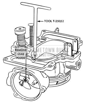
- Remove lead plug from gasket surface and lead plug from inside choke housing (use tool T -25052, KM269-S-13) (See Figure 13).
1954 Buick Stromberg Carburetor Thermostat Gasket
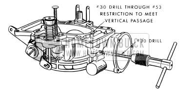
1954 Buick Stromberg Carburetor Vertical Passage
(This is approximately 1 5/64″ deep from edge of boss. DO NOT DRILL INTO OUTER WALL).
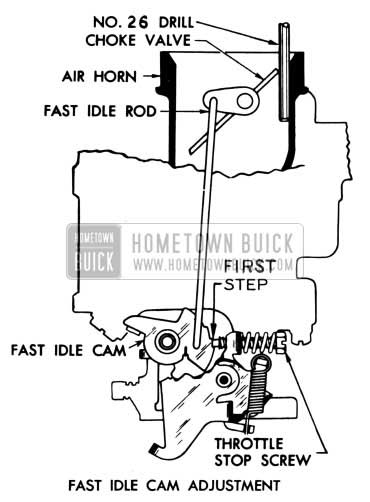
FAST IDLE CAM ADJUSTMENT (FIGURE 15)
1954 Buick Fast Idle Cam Adjustment
- Place a No. 26 drill between the upper lip of choke valve and wall of air horn. Throttle stop screw should come to rest on the first step from extreme fast idle or high point of the fast idle cam with fast idle rod against bottom of slot. Bend rod at upper end for adjustment. Check rod for free movement of the choke shaft lever and fast idle cam. Be certain that no binding exists.
START AID LEVER ADJUSTMENT (FIGURE 16)
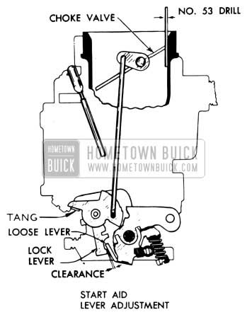
1954 Buick Start Aid Lever Adjustment
- With a No. 53 drill held between choke valve and wall of air horn, there should be just enough clearance to allow loose lever (spring loaded) on throttle shaft to pass clear of lock lever behind fast idle cam. Bend tang on start aid lever to secure desired clearance.
WIDE OPEN KICK ADJUSTMENT (FIGURE 17)
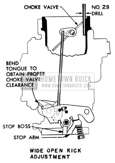
1954 Buick Wide Open Kick Adjustment
- The wide open kick should be adjusted so as to open choke valve equivalent to a No. 29 drill (shank end) when throttle is fully opened. To adjust, bend tang on throttle lever. Close choke and also throttle. Open throttle to wide open position, taking note that choke valve opens while working through tension of spring loaded loose lever.
- Assemble pump rod to pump lever.
- Place carburetor upside down and remove main discharge jet plug. Remove main metering jets and discard. (Use tool T -24924 KM 269-S-2). Assemble new metering jet P-24673 (.051″). Assemble main discharge jet plug securely.
STARTING SWITCH ADJUSTMENT (BENCH)
- The starting switch adjustments must be made after all choke and idle adjustments have been completed. With carburetor placed upside down, close the throttle until the starter switch operating lever just contacts the switch slide. With the throttle held in this position, the opening between the throttle valve and the barrel should be 3/32″ drill (.90″ to .100″). If the opening does not fall within these limits, bend the operating lever ear to secure the desired position. It is suggested that switch timing be rechecked after carburetor has been installed on automobile.
Stamp new code No. 7 -95C on carburetor.
- Reinstall carburetor on manifold. Recheck wide open kick position to be assured of full travel of the throttle linkage.
- Flat Rate. Complete Operation 1.2 hr.
REWORK OF STROMBERG 4 BARREL CARBURETOR
USE SERVICE KIT, GR. 3.725 No. 1391946
- Remove Carburetor from engine
- Remove thermostat cover assembly. Remove choke stem nut (use tool T-25047, KM269-S-10), lockwasher, serrated washer and choke piston. Remove aluminum drive plug from choke housing. Discard cover, piston and drive plug.
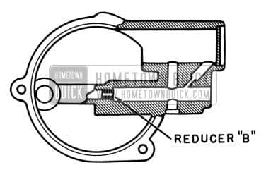
- Remove brass reducer (“A”, see Figure 18) from inside of choke housing.
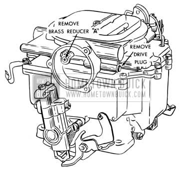
1954 Buick Stromberg 4-Barrel Carburetor
Drill reducer with No. 30 drill and use tool T-24967, KM269-S-4, or “easy out” tool for removal. Discard reducer.
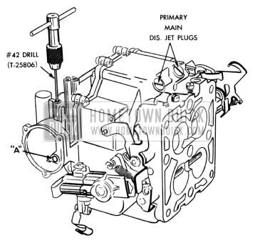
1954 Buick Rework of Stromberg 4-Barrel Carburetor
The No. 42 drill due to its special length, (3 1/4″ to 31/2″) may be difficult to locate but is available through both Cleveland Twist and National Drill Companies. The Mill Supply Houses may also be of assistance to you in obtaining this drill. If difficulty is experienced in obtaining one of these drills, contact your local Zone Service Manager.
1954 Buick Carburetor Drive Plug
Care should be exercised in drilling through this reducer. If reducer is moved out of position it can be reassembled with a standard drift pin. Be sure to remove all burrs.
FAST IDLE CAM ADJUSTMENT (Figure 21)
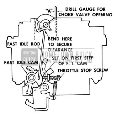
1954 Buick Stromberg Carburetor Fast Idle Cam Adjustment
- Place a No. 41 drill (shank end) (“A”) between the upper lip of choke valve and wall of air horn. Throttle stop screw should come to rest on first step from extreme fast idle or high point of the fast idle cam with fast idle rod against bottom of the slot. Bend rod at upper end. Check rod for free movement, making sure bending adjustment does not cause rod to bind in the cam or lever.
START AID LEVER ADJUSTMENT (Figure 22)
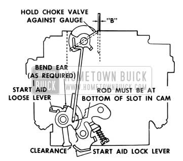
1954 Buick Wide Open Kick Admustment
- With a No. 53 drill (shank end) (“B) held between choke valve and wall of air horn, there should be just enough clearance to allow loose lever (spring loaded) on the throttle shaft to pass clear of lock lever behind fast idle cam. Bend tang on lock lever to adjust.
WIDE OPEN KICK ADJUSTMENT (Figure 23)
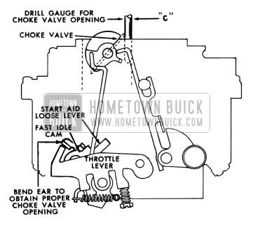
1954 Buick Lockout Slide Adjustment
- The wide open kick should be adjusted so as to open choke valve equivalent to a No. 2 drill (shank end), (“C”) when throttle is fully opened. Bend tang on start aid to adjust. Close choke and also throttle. Open throttle to wide open position, taking note that choke valve opens while working through tension of loose lever spring.
LOCKOUT SLIDE ADJUSTMENT (Figure 24 & 25)
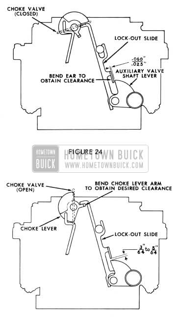
1954 Buick Stromberg Carburetor Choke Valve
- With choke valve and auxiliary valves closed, the slide should be in DOWN position. Clearance between the ear on the slide and the weighted end of auxiliary throttle shaft lever should be no less than 1/32nor more than 1/16. Bend ear of slide as required. With choke valve held wide open and auxiliary valves turned to wide open position, the clearance between the ear on the slide lever and the auxiliary shaft weighted lever should be from 3/64″ to 5/64″. Bend choke lever arm as required to secure desired clearance.
- Assemble accelerating pump rod in long stroke or extreme lower hole of throttle lever, with brass washer and cotter pin and connect to pump lever with cotter pin.
- Place carburetor upside down and remove primary main discharge jet plugs (located adjacent to idle needle valves). Remove main metering jets and discard (use tool T -24924, KM269-S-2). Assemble new metering jets, P-19442 .049″. Assemble main discharge jet plugs securely.
STARTING SWITCH ADJUSTMENT (BENCH)
- The starting switch adjustments must be made after all choke and idle adjustments have been completed. With carburetor placed upside down, close the throttle until the starter switch operating lever just contacts the switch slide. With the throttle held in this position, the opening between the throttle valve and the barrel should be 39 to 41 drill (.100″ to .110″). If the opening is not within these limits, bend the operating lever to secure the desired position. It is suggested that switch timing be rechecked after carburetor has been installed on automobile.
Stamp new Code No. 7-940 on carburetor.
- Reinstall carburetor on manifold. Recheck wide open kick position to be assured of full travel of the throttle linkage.
- Flat Rate. Complete Rework 1.5 hr.
VIBRATION-PART THROTTLE ROAR
1954 MODELS
After following the procedures authorized in BPS Bulletins 2.344 and 2.351, a few cases of noise or vibration continue to exist. This persistent noise has been traced to a part throttle roar between 30-35 MPH at road load.
Since this noise is a function of engine speed and not car speed, it may be encountered under accelerating conditions atspeedslowerthan30-35MPH. This noise occurs between 1400 to 1600 RPM regardless of speed.
NOTE: It will be necessary to use a portable tachometer when checking this type of complaint. The following procedure should be followed only after all points of interference have been removed as outlined in the above mentioned BPS Bulletins and after it is further determined that a noise still exists in the above RPM range.
- Remove rear muffler support.
- Cut off the end of rear muffler support 1″ from center of clamp bolt. See Figure 26.
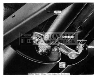
1954 Buick Muffler Support
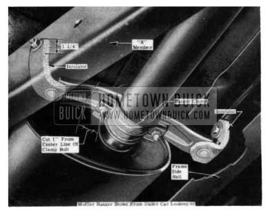
1954 Buick Muffler Support Correction
We would like to point out that the above correction is not a “cure all” and will not correct interferences or noise due to engine unbalance, etc.
CARBURETOR TOOL KIT
The Buick carburetor tool kit sold by Kent-Moore has been reviewed and brought up-to-date. Unnecessary tools have been deleted and those deemed essential have been added.
The new complete Buick carburetor tool kit, J-3233-C, may be ordered from Kent-Moore and is priced at $24.65. Each item listed may also be purchased separately from Kent-Moore.
(THIS KIT IS FOR BOTH STROMBERG & CARTER)
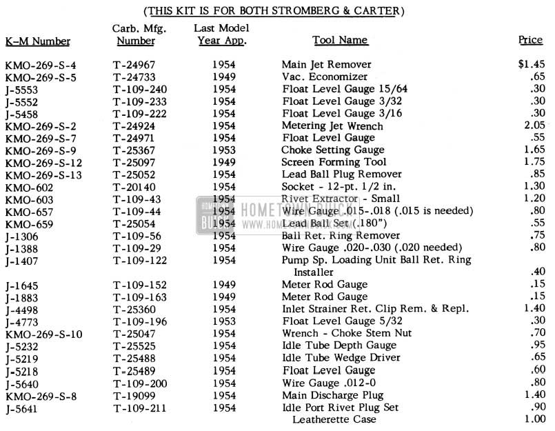
1954 Buick Carburetor Tool Prices
Leave A Comment
You must be logged in to post a comment.