REAR AXLE BREATHER
1954 MODEL
To eliminate the possibility of oil leaks occurring at the rear axle housing, effective about the 1st of June all jobs will have a breather, Gr. 5.387 Part No. 3700490 installed in the rear axle housing.
The following procedure is recommended for installing the breather in the field. Remove left axle shaft, and ring gear. Drill a .359-.369 diameter hole on top of the housing, 14″ maximum from center line of carrier, Figure 35.
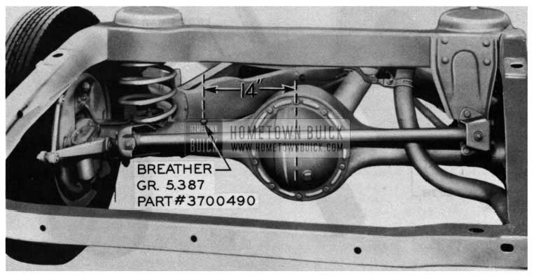
1954 Buick Rear Axle
NOTE: Place rag with grease on it in axle housing to prevent any chips from entering the axle housing.
Drive breather into place. Re-check to make sure no chips fell into housing, replace axle shaft, ring gear and adjust according to the Shop Manual, page 6-6. This axle breather is not to be campaigned.
The flat rate time to make this installation is 2.0 hr.
REAR AXLE PINION SETTING GAUGE REWORK
The rework of the pinion setting gauge adapter, J-2197-9, as covered in a previous article, does not completely overcome the problem of being able to position the adapter so that a good micro meter reading can be made. This problem is due to the following:
- The unground portion on the end of the pinion gear varies in width and sometimes is very close to the same diameter relief cast into the adapter. Therefore, in some cases it is impossible or extremely difficult to make the adapter fit squarely on the pinion.
- When the adapter is centered on the pinion and the micrometer is as far to the left as possible it is difficult to swing the micrometer through its arc and make a good contact with the ground portion of the adapter.
The following is a correction to make the pinion setting gauge work satisfactorily:
- Use the old adapters, J-681-37-1 on pinions mounted in the narrow saddle carriers.
- Rework the adapter, J-2197-9, and the pinion setting gauge as outlined below and use the reworked adapter, J-2197-9, on pinions mounted in the wide saddle carriers The reworked adapter, J-2197-9, will not work on the small pinions used in the narrow saddle carriers.)
REWORK OF ADAPTER, J-2197-9:
The cast cavity in the center of the gauge adapter, 1-2197-9, must be made wider. Machine out 3/16″ of the ground face to the same depth as the balance of the cavity as shown in Figure 36. This will increase the diameter of the cavity by 3/8 of an inch. Be sure not to bend or distort the adapter during machining and be certain to remove all burrs on the ground surface.
REWORK OF THE PINION SETTING GAUGES, 1-2197, and 1-681-A:
Remove the collar that is on the short side of the cross bar and increase the depth of the counterbore 1/4 of an inch as shown in Figure 37.
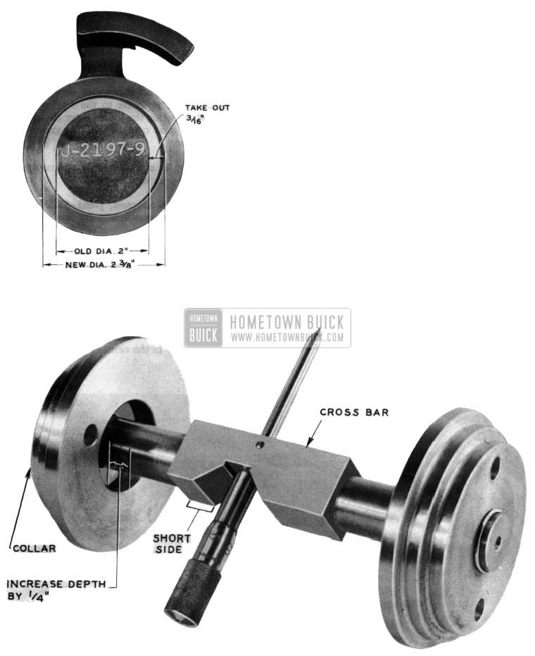
1954 Buick Rear Axle Cross Bar
Place the collar back on the cross bar.
INSTRUCTIONS ON USE OF REWORKED GAUGE AND ADAPTER:
The reworked gauge adapter, 1-2197-9 must be centered on the end of the pinion. (Use only reworked 1-2197-9 gauge adapter on pinions in wide saddle carriers.) Rotate the adapter so that the ground indicating surface is to the left of the pinion vertical center line so that the micrometer contacts the center portion of the surface when it is swung through its arc. The gauge adapter must be held in position with the new clamp supplied in the J-2197-15, pinion setting gauge adapter kit.
Arrangements have been made with Kent-Moore to rework and recalibrate the J-2197 and J-2197-A pinion setting gauges for a fixed charge of $8.50. The rework and recalibration will consist of the following:
- Rework and check gauge adapter, J -2197-9.
- Rework collar of gauge.
- Check and rework master checking gauge.
- Check and recalibrate micrometer.
The complete pinion setting gauge, consisting of the micrometer gauge, adapters, and checking gauge are to be sent to Kent-Moore Organization, Inc., 1501 S. Jackson St., Jackson, Michigan, attention: Service Repair Department. When the gauge is received at Kent-Moore, it will be inspected and if in their opinion the specified work will not place the gauge in satisfactory working order, it will not be reworked and will be returned as received. This policy will be adhered to as the cost of additional repair operations would be prohibitive.
The J-2197-A pinion setting gauges as ordered on the 1953 after tool program order blank did not include the J -681-37-1 gauge adapter as it was felt at that time that the J -2197-9 would work on all gears. In view of these new instructions, the J-681-37-1 is necessary and will be shipped upon request free of charge to those dealers who purchased the J-2197-A. Requests for the J-681-37-1 should be addressed to Kent-Moore Organization, Inc., General Motors Building, Detroit 2, Michigan.
At the request of Buick, Kent-Moore has discontinued the sale of the J-2197-A, pinion setting gauge, effective February 1, 1954. A new direct reading dial indicator type gauge has been developed.
PINION SETTING INDICATOR GAUGE
A new direct reading dial indicator gauge has been developed and will be manufactured and sold by Kent-Moore. The new gauge is direct reading, easy to use, and takes one third the time to use as compared to the micrometer type gauges. This new pinion setting indicator gauge, J -5647, is priced at $62.00, less the dial indicator, and will be ready for delivery approximately May 15, 1954. The dial indicator, KM0-30-B, is the same one as used for checking rear axle ring gear back lash, Dynaflow alignment and many other operations covered in the Buick Shop Manuals. The new indicator gauge set is shown in Figure 38.
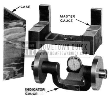
1954 Buick Pinion Setting Indicator Gauge
The set consists of the indicator gauge (less dial indicator), master gauge, and storage case.
To use the indicator gauge it is first placed in the master gauge as shown in Figure 39 and the dial indicator is set at “0”.
1954 Buick Pinion Setting Center Indicator Gauge
The gauge is then placed in the rear axle assembly as shown in Figure 40 and depth of the pinion is shown by the reading of the indicator.
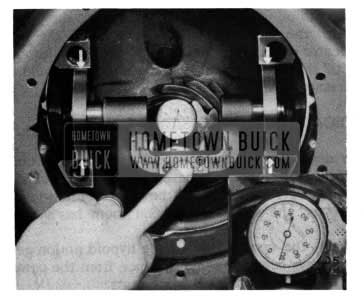
1954 Buick Pinion Setting Indicator Gauge Measurements
If the pinion is marked t 8 and it is set to the proper depth, the indicator will read t 8. If the dial indicator reads +6, it would be necessary to remove a .002 shim. If the indicator reads t 10, it would be necessary to add a .002 shim.
INDICATOR GAUGE DESIGN:
The design of the new gauge is based on four conditions. First, the diameter of the side carrier bearing seats has remained the same for many years. However, the distance between them has varied.
Second, the center line of the hypoid pinion gear has always been the same distance from the center line of the side carrier bearing seats.
Third, a center placed in the center drilled hole of the pinion tends to align itself perpendicular to the face of the pinion gear. This condition is similar to placing a drill into a drill bushing.
Fourth, each pinion gear has the following information stamped or etched on the face as shown in Figure 41.
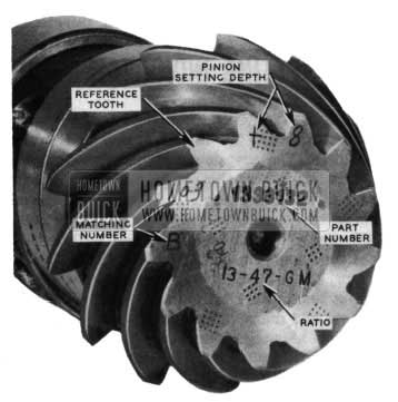
1954 Buick Master Gauge Design
- Part number
2. Ratio
3. Matching number
4. Pinion setting depth
A blank tooth will always be found between the teeth with the etched matching number and the pinion setting depth as shown in Figure 41. This blank tooth will be referred to as the “reference tooth”. The reference tooth is the tooth that is used in all the manufacturing processes for locating purposes and for measuring the pinion depth during assembly. The new pinion setting indicator gauge, J-5647, also uses the reference tooth for measuring the pinion depth.
The design of the indicator gauge as shown in Figure 42 incorporates these four conditions in the following manner. The yoke has two sliding disks so as to accommodate both the narrow and wide saddle side carrier bearing seats. The yoke also has a spring loaded center which fits into the center of the pinion gear and aligns the gauge assembly .The dial indicator is held in position in the yoke with a thumb screw so that it may be held in either of two positions depending on the ratio marking of the pinion gear. (NOTE: Use contact point “C” as shown in Figure 42).
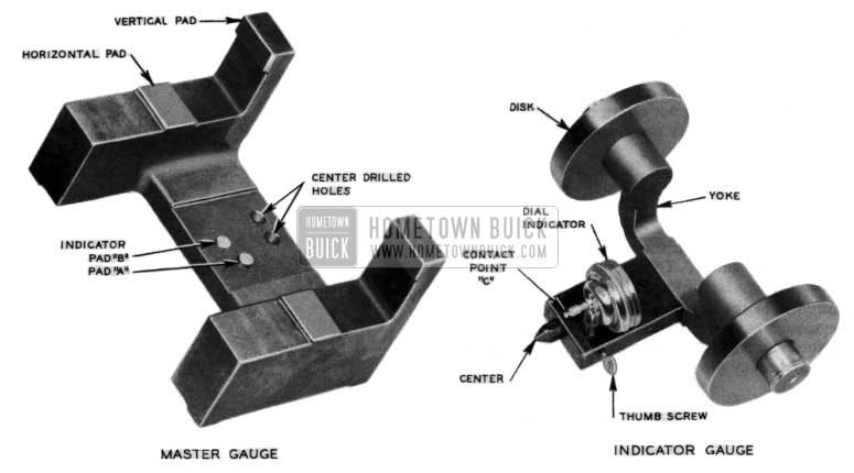
1954 Buick Master and Indicator Gauge
The yoke is stamped with two arrows; one is marked plus (t) and the other is marked minus(-). These arrows designate whether the indicator is reading plus or minus.
MASTER GAUGE DESIGN
The design and operation of the master gauge as shown in Fig. 42 incorporate one additional condition to the four previously described. There is a known distance from the face of the pinion gear to the center line of the side carrier bearing seats for an “0” pinion setting depth. For purposes of explanation this distance will be referred to as “X” inches”. The plus and minus pinion setting depth markings on a gear indicate whether the “X inches” distance must be increased or decreased for the best possible gear performance. For example, for a pinion that is marked .f 8 the “X inch” dimension must be increased by .008 of an inch. For a pinion marked – 8 the “X inch” dimension must be de creased by .008 of an inch.
The plus or minus marking on the pinion gear is used when setting pinion depth. The “X inch” dimension has been built into the master gauge and is therefore automatically taken care of.
The master gauge (See Figure 42) has two center drilled holes to receive the spring loaded center of the indicator gauge, two corresponding indicator pads, “A” and “B”, that are used to set the dial indicator to “0” and two vertical and two horizontal pads that locate the disks of the indicator gauge.
INSTRUCTIONS FOR USE OF J -5647, PINION SETTING INDICATOR GAUGE
Calibrate the indicator gauge.
- Make certain that the spring loaded center and the disks of the indicator gauge are clean.
- Make certain that the center drilled holes, indicator pads and vertical and horizontal pads are clean.
- Select the proper indicator pad and center drilled hole in accordance with the table shown at the end of this article.
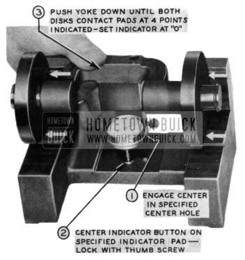
- Place the indicator gauge on the master gauge (See Figure 39) by first entering the center of the gauge into the specified center of the master gauge.
- Center the indicator button on the specified indicator pad and lock the indicator in place with the thumb screw.
- Push the yoke down (See Figure 39) until both disks contact the pads at all four points and set the indicator at “0”.
READ THE PINION DEPTH
- Shift the Dynaflow transmission out of Park position and the Synchromesh transmission into neutral.
- Rotate the pinion so that the reference tooth is slightly to the left of upper center.
- Make certain that the side carrier bearing seats are clean and free of burrs.
- Make certain that the center in the pinion is clean and free of grit or foreign material.
- Place the indicator gauge in the carrier with (See Figure 40)
- The disks fully seated in the side carrier bearing seats, clear of the threads and the inner edges of the seats.
- The gauge center engaged in the pinion center.
- Indicator button on the reference tooth.
- The yoke pressed in against the pinion gear.
- Read the dial indicator making certain to note whether the reading is plus or minus.
- Place the indicator gauge back on to the master gauge. The indicator should again read zero. If the indicator does not return to zero repeat the entire operation as the gauge was either loose or it was bumped.
COMPARISON OF PINION SETTING GAUGES
It is recognized that there can be a slight difference in the readings between the micrometer gauges and the indicator gauge. This is acceptable and the indicator gauge is considered the most accurate. The difference in reading may be attributed to many things, such as miscalibrated micrometers, damaged adapters, burrs, machining allowance within the gauge and many other factors.
Indicator Pad Indicator Pad
“A” “B”
For pinions marked For pinions marked
11-49 11-43
14-51 12-43
10-41 12-41
13-47 13-42
Leave A Comment
You must be logged in to post a comment.