1954 LOW BAND AND CLUTCH
REPRINT OF SPECIAL LETTER, NO. 142
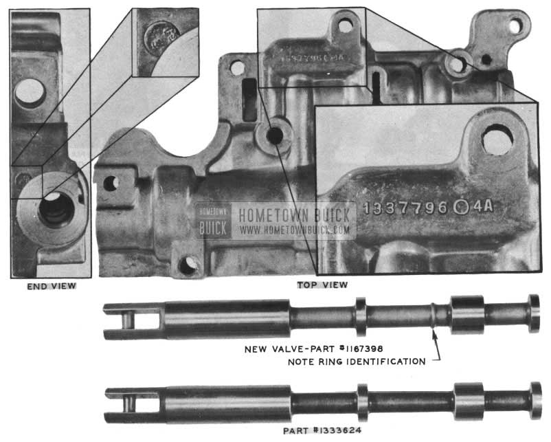
In the second paragraph we stated that Engineering would release a special shift control valve with wider lands which will enable the use of the “4A” valve bodies by replacing this valve only, on the valve bodies that are marked by a date (9 -53 through 2-54, first number indicating the month) stamped on the pressure regulator end of the valve body. See illustrations.
The new shift control valve, Group 4 .218 Part No. 1167398, permits use of those “4A’s” mentioned above and can be easily identified by a ring on the valve between the 2nd and 3rd land, see Figure 28.
1954 Buick Low Band and Clutch
Approximately 20,000 “4A” valve bodies accumulated between the above dates will have the new shift control valve installed in production, however, the “A” will be ground off of the valve body.
“4A” valve bodies marked by a date before 9-53 such as 8-53 etc. do not have to be replaced as stated in dealer letter No. 140 and they require shift control valve No. 1333624.
“4A” valve bodies dated 9-53 or later, do not have to be replaced if shift control valve Part No. 1167398 is used.
“4” valve bodies (with the “A” ground off) also require shift control valve 1167398.
Valve bodies marked other than “4” or “4A” (dated 9-53 or later) require valve No. 1333624.
FROZEN SHIFT CONTROL IDLER LEVER
1954 SERIES 50-70
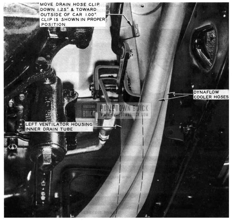
Some cases have been reported where the shift control idler lever has become frozen due to water draining on it from the left ventilator inner drain hose. If this condition occurs, the following rework is suggested.
- Remove original drain hose from car.
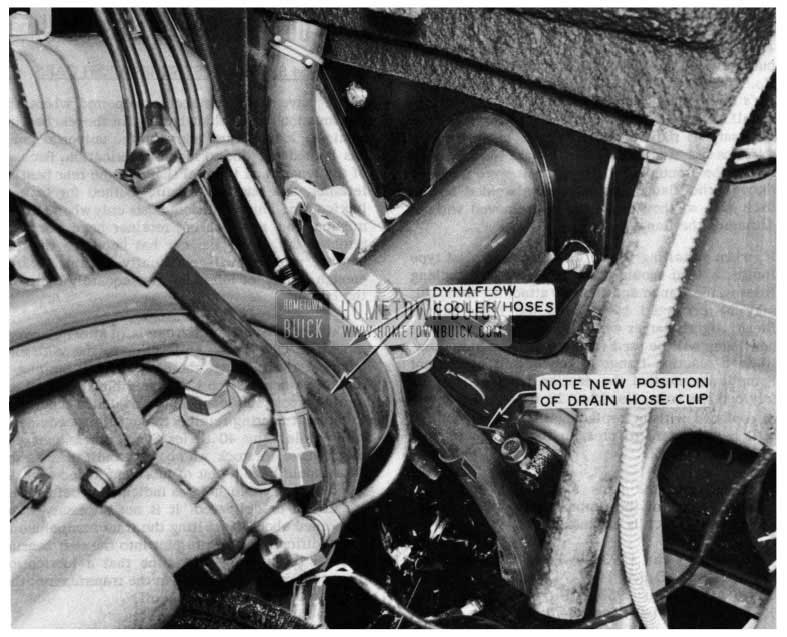
- Reposition the ventilator drain tube hose clip as illustrated in Fig. 29 & 30.
1954 Buick Shift Control Idler Lever
1954 Buick Ventilator Inner Drain Hose
This new hose clip position is 1 1/4″ down and 1″ outward from its present position, to left side of the car.
(c) Remove temperature control valve retainer screws on front of dash and pull valve forward through opening in dash.
NEW DYNAFLOW FRONT PUMP
1954 ALL SERIES
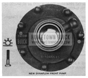
To eliminate the Dynaflow transmission front pump mounting bolt locations as a source of oil leakage, a new front pump Part No. 1391884 has gone into production effective February 24, 1954 with transmission No. 070. When this change was made the Square Head Front Pump Attaching Bolts, which were pressed in the reaction flange, were removed and cap screws installed from the back side of the flange in their place. These cap screws screw into the blind holes in the front pump body. See Figure 31.
1954 Buick New Dynaflow Front Pump
In order to incorporate the advantages of this new pump for service replacements the old pump will be replaced by the new pump as soon as stock on hand is exhausted. When installing this new pump on a 1st type reaction flange, it will be necessary to press out the Square Head Bolts, Group 4.226, Part No. 1340122 from the flange and use seven (7) Group 8.900, Part 179821, Bolts and seven (7) Group 4.226, Part No. 1166045, Locks. When the new pump is used on a 1949-50 D.F. up to transmission No. B-28999 or a 1949-70 D.F. between transmission No’s 55999 and A-86599. it will be necessary to install a new Reaction Shaft and Flange. This is necessary as the Reaction Flanges in these transmissions use studs instead of Square Head Bolts to retain the front pump. These studs were threaded through the flange and nuts were welded on the back side so they could not be removed without damaging the flange.
If, when installing a new front pump on a 1st type flange, a bind should occur between the attaching holes in the flange and the new attaching bolts, this may be corrected by drilling the holes in the flange slightly larger with a 11/32″ drill. Since the new Pump will be used for service and in most cases when a reaction flange is required, a new Front Pump is also needed, the reaction flange will now be serviced less bolts, No. 1340122. If a reaction flange is replaced without replacing the Front Pump, it will be necessary to press in the old Square Head Bolts, No. 1340122.
Following are the parts affected by the above changes. None of the replacements will be made until the old stock is exhausted.
Group 4.224- Part 1393849- Pump-Dynaflow Front Oil 1949-50 D.F.; 1949-70 D.F. after Trans. 55999; 1950 thru 1953 D.F.; 1954 up to Trans. K-070 on 40; M-070 on 50-70; L-070 on 60-100.
To be replaced by:
Group 4.224- Part 1391884- Pump Dynaflow Front Oil 1954 after Trans. K-070 on 40; M-070 on 50-70; L-070 on 60-100.
Group 4.226 – Part 1342318 – Shaft and Flange Converter Reaction 1948 thru 1952.
To be replaced by:
Group 4.226 – Part 1167353 – Shaft and Flange Converter Reaction
Group 4.226 – Part 1318699 – Shaft and Flange Converter Reaction 1953-1954 After-Jobs.
Group 4.226 – Part 1166330 – Shaft and Flange Converter Reaction 1954 After-Jobs.
To be replaced by:
Group 4.226 – Part 1167352 – Shaft and Flange Converter Reaction.
BURNED OUT TRANSMISSION OUTPUT SHAFT BUSHING
1954 SERIES 40 SYNCHROMESH CARS
There have been some cases reported where the transmission output shaft bushing in the rear bearing retainer, located just ahead of the universal joint, has burned out due to lack of lubrication. Because of the length and internal shape of the rear bearing retainer, this bushing is being burned for lack of lubrication. This condition exists only when a transmission and rear bearing retainer have been assembled dry. After the car has been run the rear bearing retainer will eventually obtain a large enough supply of lubricant to adequately lubricate the bushing.
All 40 Series Synchromesh cars built after Feburary17 should be OK. Those built prior to the 20th may burn out the bushing; therefore, if the bushing is replaced when the job is reassembled a pint of the multi-purpose lubricant should be added separately to the rear bearing retainer through the speedometer cable hole. Any 40 Series Synchromesh cars you might have in stock which were built prior to the
20th should have a pint of lubricant added thru the speedometer cable hole as indicated – before they are driven or delivered. lt is not necessary to be concerned about overfilling the transmission due to the addition of this extra pint into the rear bearing retainer because the first time that a lubrication man checks the oil level in the transmission, this pint can be permitted to run off.
When replacing the bushing on the few jobs that may bum out, care should be taken to see that the lubricant hole in the bushing is lined up with the lubrication passage drilled into the rear bearing retainer which supplies oil from throw off at the top of the
SHIFT CONTROL HOUSING SCRAPING NOISE
ALL 1954 DYNAFLOW JOBS
Some reports have been called to our attention that a scraping noise was heard when shifting between ranges on Dynaflow jobs. This was caused by the directional signal wire cable clamp being incorrectly positioned causing it to rub on the shifter control housing. (See Fig. No. 32)
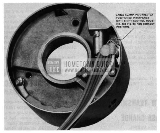
1954 Buick Dynaflow Cable Clamp
On jobs where this trouble is encountered it will be necessary to reposition cable clamp and tighten screw to hold clamp in correct position as shown in Figure 33.
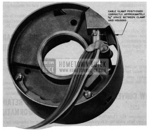
1954 Buick Dynaflow Cable Clamp Correction
NEW REACTION FLANGE BOLT
1954 ALL SERIES
A change was made in production to use a longer front pump to reaction flange bolt Gr. 8.900 Part No. 179822 (5/16 – 18 x 1 1/2) instead of the 5/16 x 18 x 1 3/8″ bolt Gr. 8.900 Part No. 179821. When using the new length bolt with a 1st type front pump, a bottoming tap should be used in the seven (7) tapped holes in the front pump body so that the depth of the threads is .562. This is approximately one full turn of the tap past the old thread depth.
Parts Department will continue to ship the shorter bolt Gr. 8.900 Part No. 179821 until all stock is exhausted.
DYNAFLOW TRANSMISSION CASE CHANGE
1954 MODEL
Effective with the following Dynaflow transmission No. Series 40 – K -087, Series 60 – L -08, Series 50 & 70 – M-087, the planet carrier front thrust washer (steel) Gr. 4.176 Part No. 1333095 was eliminated from the transmission.
The transmission case was revised to add stock to the case which takes the place of the washer.
The Parts Department will continue to service the first type transmission case Gr. 4.103 Part No. 1165643 until stock is exhausted, at which time they will replace the 2nd type case Gr. 4.103 Part No. 1166589 effective with the above transmission numbers.
If it becomes necessary to use a 1165643 case in a job, the thrust washer must be used. When the stock of 1165643 is exhausted and 1166589 is used, the thrust washer must not be used.
NEW DYNAFLOW CONVERTER PUMP
1954
To strengthen and improve the Dynaflow Trans mission Converter Pump, bolt pads have been added on the flange around the outside diameter of the pump.
The new Pump, Gr. 4.115, Part No.ll66608will be used for all replacements of the old Pump, Gr. 4 .115 Part No. 1318693 which was used in all 1953 and 1954 1st jobs Dynaflow transmissions.
When installing the new pump as a replacement, it will be necessary to order and use the new bolts, Gr. 4.115 Part No. 1166156duetothelonger length. Since the method of attaching the balance weights was also changed, new weights are released for use on these pumps when they are required. These weights are Gr. 4.115 Part No’s. 1166600 (.0345 thick), 1166601 (.060 thick) and 1166602 (.120 thick).
The old bolt and balance weights will continue to be available.
SYNCHROMESH TRANSMISSION JUMPING OUT OF SECOND GEAR
1953 SERIES 40
In the past few months, complaints have been received from the field of the 1953 Series 40 Synchromesh transmissions jumping out of the second gear. In each case, the cause has been traced to the omission of the Universal Joint Spacer, Gr. 5.579 Part No. 1323136, shown in Figure 34.
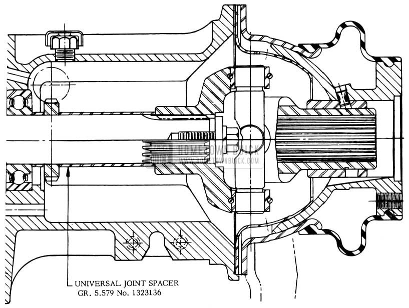
1954 Buick Universal Joint Spacer
The omission of this spacer allows the main shaft to move forward into the clutch gear. This pulls the sliding sleeve out of the second speed gear and also pulls the center point of the universal joint away from the center point of the torque ball. Hence, the transmission jumps out of second gear.
When the above condition is encountered, it should be corrected by the installation of the Universal Joint Spacer, Gr. 5.579 Part No. 1323136.
TORQUE TUBE TO CARRIER GASKET FLAT RATE ADDITION
FLAT RATE MANUALADDITIONALOPERATION GASKET TORQUE TUBE TOCARRIER –INSTALL OR REPLACE 1.3 4-80
Includes: D&C strut rods to banjo housing – (5.508) torque tube to carrier – move banjo and carrier back enough to install gasket. (Cut at top)
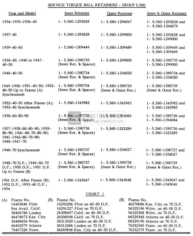
TORQUE BALL RETAINERS, PARTS INFORMATION
Since a number of changes have been made in the method of servicing Torque Ball Retainers, Chart No. 1 has been compiled to eliminate any confusion which might exist in the field as to the correct part to use. This chart shows the part number to use when replacing an Inner or Outer Retainer separately and also indicates the parts needed if both the Inner and Outer Retainers are required.
In some cases, due to the above mentioned changes, it has been necessary to service the Inner Retainer with a package consisting of an Inner Retainer and a Spacer. Also, in some cases, the Outer Retainer must be replaced by a package consisting of an Inner and Outer Retainer. These packages are noted on the Chart. In no case is the Spacer required separately and consequently it is not released separately.
1954 Buick Service Torque Ball Retainers
Leave A Comment
You must be logged in to post a comment.