In performing air conditioner service operations and replacing parts, the system must be prepared and processed, before and after the work is performed.
The first of these procedures we want to discuss is “Pumping,’ Down the System.” In this step we pump the refrigerant into the receiver so as to save as much of it as possible.
In order to save time and to avoid repetition, we will now cover the step-by-step procedure and in other operations, only a reference to “Pumping Down” will be made.
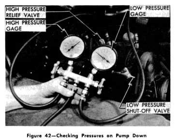
1953 Buick Checking Pressures on Pump Down
- Pumping Down the System
- Remove the protective caps and install the lines of the gage set to the high and low pres sure gage connections on the compressor.
- Close the liquid line valve at the receiver.
- Remove the caps from the low and high pressure hand shutoff valves on the compressor.
- Purge the gage lines by cracking open the hand shutoff valves on gage set. IMPORTANT NOTE: Under some conditions of overcharge the receiver and condenser will not hold the en tire charge of refrigerant, therefore, it may be necessary to discharge some of it during the pump-down operation. lf the high pressure side reaches 275 pounds, TURN THE ENGINE OFF, then discharge refrigerant through the high pressure side of the gage set to the atmosphere in sufficient quantity to prevent the pressure from exceeding this amount.
- Energize the by-pass valve by connecting a wire from the hot side of the battery to the solenoid.
- Turn the control switch “ON” and operate engine below 700 R.P.M.
- Watch both gages and allow the compressor to operate until the “low” pressure gage reads 0 (zero) pounds. Then close the “low” compressor valve, stop the engine, turn “OFF” the air conditioning switch, and close the high pressure hand shutoff valve at the compressor. DO NOT start the engine! Purge the remaining refrigerant from the “low” side through the “low” gage allowing 1 or 2 pounds pressure to remain in the low pressure side of the system. Open the “low” side of the compressor. If pres sure builds up above 5 pounds, purge again. Then close the low pressure valve on the compressor.
The system has now been prepared and you should be ready to perform certain service operations-keeping in mind that the by-pass valve must be kept “closed’ by the jumper wire, as directed in Step No. 5, until the service work has been completed and the side evacuated. Otherwise the refrigerant in the condenser and receiver will be lost through the “low” side.
To maintain chemical stability in the system one of the most important pieces of servicing equipment is the vacuum pump. Whenever the system is opened for performing service operations or repairs, it should not be put into Operation again until it has been evacuated. This is necessary to remove air and moisture which will have entered the system when the system was opened to replace a part. In later discussing some of the service operations requiring evacuation, only a reference will be made to it, so, let’s discuss the procedure for evacuating the system.
- Evacuating the System
Because we are now evacuating only the low pressure side of the system it is to be assumed only this side was opened to atmosphere.
Any leak causing a complete loss of refrigerant will require a complete evacuation following service corrections.
- Evacuating the Low Pressure Side of the System.
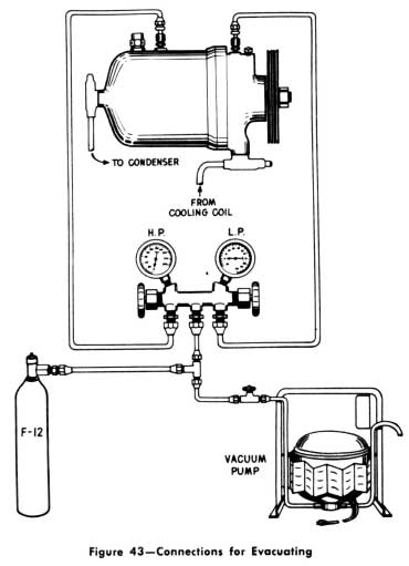
1953 Buick Connections for Evacuating
- Check to be sure the compressor high pressure hand shut off valve, liquid line valve at the receiver, and the by-pass valve are all closed, as carried over from the “Pump Down” procedure.
- Connect the vacuum pump, freon cylinder, and gages to the compressor as shown in Figure 42.
- Make certain the low pressure hand shutoff valve at the compressor is open. (The high pressure valve must be closed.)
- Start the vacuum pump.
- Open the low pressure gage valve.
- Slowly open the shutoff valve at the vacuum pump to avoid forcing oil out of the pump.
NOTE: lf the vacuum pump oil is blown out it should be replaced with Frigidaire 75 viscosity oil (28 oz. is the capacity). - Operate to obtain at least 26″ vacuum for 10 minutes with vacuum pump running. (lf a 26″ vacuum cannot be obtained, close the shutoff va1ve at the pump and stop the pump. Open the refrigerant cylinder valve and allow the “low” side of the system to come to cylinder pressure. Close the cylinder valve. Leak-test the complete low side of the system, including gage hookup fittings, with leak detector. If the leak cannot be found, the vacuum pump is probably faulty.)
- Close the shutoff valve at the vacuum pump and stop the pump. Watch the gage to see if the vacuum holds. If it will not hold, charge some Freon-12 into the system and leak-test. Correct the leak and pull the vacuum again.
- Open the refrigerant cylinder valve to charge the system to cylinder pressure. (Gages should equalize) Close the cylinder valve.
- Evacuate the system again as previously described. This second charging and evacuating is for the purpose of picking up any air or moisture that may have remained in the system.
- Shut off vacuum pump valve then pump.
- Remove the jumper wire from the battery to the solenoid, and open the compressor high pressure hand shutoff valve and the liquid line at the receiver.
The system is now ready for adding of refrigerant as and when required.
- Evacuating the Entire System :
NOTE: If the “low” side has been “pumped down,” and it is then found desirable to evacuate the complete system, do not attempt to evacuate the “high” side, through the vacuum pump, until it has been purged directly to atmosphere. Follow the same steps as outlined for evacuating the “low” side of the system, and in addition, open the high pressure valve at the receiver, open the high pressure valve at the compressor, and open the high pressure valve on the gage set.
- Checking for Air – Purging Air and Refrigerant from the System
Air in the system can be easily differentiated from an overcharge of refrigerant. In order to check for this condition, the car engine and compressor must be stopped ; then follow the procedure described below:
- Connect the high pressure side of a gage set to the high pressure gage connection on the compressor.
- Open the valve on the high pressure side of the gage set, allowing vapor to exhaust slowly through the center connection on the gage set for 5 to 8 seconds, then close.
- Clip the 5/8″ thermo-well on the inlet tube of the condenser. Fill the well cavity with water and insert a 0-220° F. thermometer in it.
- Operate the engine at a speed of approximately 1600-1700 R.P.M. for about ten minutes with the air condition control switch “ON.” This will tend to concentrate any air or excessive refrigerant in the condenser or compressor. CAUTION: Do not allow the “high” side pressure to exceed 275 pounds pressure. (See “Pump Down Procedure.”)
- Keep by-pass valve energized with jumper wire and shut off ignition, valve at receiver and “low” side of the compressor.
- Allow the system temperature to settle to room temperature, observing the high pressure gage and the thermometer.
If the “high” side pressure reduces as the condenser cools and conforms to the pressure temperature relationship of Freon-12, the difficulty was due to an overcharge of refrigerant.
On the other hand, if the pressure does not reduce as the condenser cools, there is air in the system, because air does not have the same pressure-temperature relationship as Freon-12. When either of these conditions is found, it will be necessary to purge the “high” side of the system as follows:
- Open the “high” side valve on the gage set slowly for approximately 5 to 8 seconds, and allow the vapor (and possibly air) to exhaust at the center connection on the gage set.
CAUTION: Cover the connection with a cloth to prevent oil and refrigerant from contacting persons or objects. - This should be done at frequent intervals observing the pressure gage and thermometer, until the two correspond to the correct Freon-12 pressure temperature relationship.
NOTE: Since an overcharge of refrigerant would already correspond to the Freon-12 pressure-temperature relationship, it will only be necessary to purge the excessive Freon-12 until the “high” side pressure does not build up rapidly above 275 pounds when the engine is operating. - Open the low side hand shutoff valve on the compressor and operate the engine at a speed of 1600- 1700 R.P.M. with the air conditioning control switch “ON.”
- Check the operating “high” side pressure and the sight glass.
- When satisfied with the operation of the system, shut engine and unit off, disconnect the gage set, and replace the flare nuts.
- Checking and Adding Oil
The compressor was originally charged with 20 +/- 2 ounces of 525 viscosity Frigidaire oil. Because of the affinity of Freon-12 for oil, a certain amount of oil will circulate throughout the system along with the liquid and vapor during normal operation. To determine if the compressor has sufficient oil, an elbow fitting has been placed on the underside of the shell. It has a Schrader valve core, and is capped with a flare nut and deadhead.
- Procedure for adding oil after a major loss.
If any major loss of oil has occurred, such as a seal leak, line breakage, etc., this procedure should be followed: (lt is to be carried out after making the necessary repairs, evacuating and recharging the system.)
- Close both the high and low pressure hand shutoff valves on the compressor.
- Using a gage adapter on the “high” side gage connection, purge the pressure until the escaping vapor produces only a slight hiss. Re peat if necessary to be sure pressure is at a minimum.
- Remove the valve flange mounting bolts, and remove the high and low shutoff valves from the compressor.
- Remove the belts and the compressor from mounting brackets and transfer the compressor to the work bench.
- Remove the high pressure relief valve.
- Invert the compressor and drain the oil into a clean container. NOTE: Examine the condition of the oil to determine whether or not it is contaminated with any foreign material, such as metal chips, water, sludge, etc. (If foreign material is found replace compressor.) The oil should be discarded and new oil used. If any amount of water is found, flush compressor with 8 ounces of Frigidaire oil and install a new liquid dehydrator-filter.
- Pour 16 ounces of 525 viscosity Frigidaire oil from ä graduated bottle into the compressor at the high pressure relief valve opening. (lf the refrigerant has been completely discharged use 20 ounces of oil.)
- Replace the high pressure relief valve using a new copper gasket.
- Reinstall the compressor to engine mount, then connect the high and low pressure hand shutoff valves using new “0” rings and valve flange gaskets; replace the belts.
- Open the high pressure hand shutoff valve and, by using the gage adapter on the high pressure gage connection, purge the compressor.
- Open the “low” side hand shutoff valve.
- Leak test all connections which have been disturbed or repaired.
- Procedure for checking oil.
lf a slight refrigerant leak is found which indicates some loss of oil, by the presence of oil around the leak, or it is necessary to determine whether or not the compressor has a sufficient amount of oil in it, these steps should be followed:
- Start engine and turn the cooling control switch to the “ON” position and the blower controls turned to the “HIGH” position.
- Run the engine at 1600 to 1700 R.P.M. for five minutes.
- Turn off ignition and control switches.
- Remove flare nut and deadhead from the oil test fitting.
- Depress the Schrader core allowing the first surge of oil to escape. lf oil continues to escape with the Freon vapor, the oil level of the compressor is to be considered satisfactory.
NOTE: Allow the escaping oil and vapor to blow against a clean white cloth. The cloth should become oily. - If oil does not continue to escape from the test fitting, the oil is below the minimum Ievel, and therefore, oil will have to be added. c. Procedure for adding oil when below minimum Ievel.
If oil did not continue to escape from the test fitting, the oil is below the top of a small tube attached to the end of the elbow.
This tube projects into the compressor housing. If the oil Ievel is to the top of the tube, it is at the minimum safe Ievel.
If the check shows the oil Ievel to be below this point, the condition should be corrected by performing the following operations:
- Shut off the high and low pressure hand shutoff valves on the compressor.
- Using a gage adapter on the high pres sure test connection, purge off Freon until the escaping vapor produces only a low audible hiss. Wait a few minutes and repeat the purging.
- Remove the high pressure relief valve.
- Pour from a graduated bottle 4 ounces of 525 viscosity Frigidaire oil into the high pressure relief valve opening.
- 5. Replace the high pressure relief valve using a new copper gasket.
- Open the high and low pressure hand shutoff valves.
- Purge the compressor. Using a gage adapter on the “high” side gage connection of compressor.
- Recheck for the oil Ievel as indicated in Step 5 of “b” procedure for a slight loss of oil.
- If the oil is still below the minimum Ievel, continue to add 4 ounces at a time by following the steps outlined above until satisfactory Ievel is reached.
- When the satisfactory Ievel is reached, make certain both high and low pressure shutoff valves are open, then replace the flare nuts over the valve stems.
- Replace the deadheads on the oil test fitting and “high” side gage connections.
- Leak test all connections which have been disturbed.
- Run the engine and air conditioning unit for 10 minutes at 1600 to 1700 R.P.M. then check the refrigerant in the sight glass and add if necessary.
- Adding Refrigerant
If the entire charge of refrigerant has been lost through accident, or in the replacement of any of the components, the loss must be replenished. Procedure “a” below outlines the steps to be followed.
lf the diagnosis indicated a shortage of refrigerant, Freon-12 is to be added as outlined in procedure “b” below.
An important rule to follow in charging is that refrigerant should always be added to the compressor in a vaporous state. Another important rule is never to add refrigerant until the system has been leak tested and properly processed.
In order to charge refrigerant in the vapor state, the Freon-12 drum will require some heat. This can best be accomplished by placing the drum in a bucket of hot water. The temperature of the water should not exceed 125° F. Since the temperature of the water and drum will decrease, as the vapor leaves the drum, the water and drum will be cooled. This may result in a lowering of the drum pressure to the ex tent where it will be necessary to replenish or reheat the water.
It is extremely important that the Freon in the cylinder not to be heated over 125° as the fusible plugs in the cylinder and valve have a melting point of 157° and even soften at a lower temperature.
Both the Freon-12 drum and bucket of hot water should be placed on suitable scales, with the drum in an upright position. Note the scales reading before opening the valve on the drum so you can determine when 7 pounds of refrigerant has been charged into the system.
NOTES: In all refrigerant charging procedures where the compressor is in operation, the following precautions should be observed:
- The high pressure should not exceed 275 pounds.
- The low pressure hand shutoff valve on the gage manifold should be closed completely. When the gage is closed it will indicate the “low” side pressure in the compressor.
- The drum pressure should always be maintained above the minimum of 12 lbs. (and not to exceed a maximum of 90 to 100 pounds during storage).
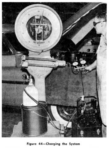
1953 Buick Charging the System
NOTE : It is to be assumed that in adding a complete charge of refrigerant the entire sys tem has been evacuated and checked for leaks, and the lines and gages are set up for adding refrigerant.
- Check the weight of the cylinder, bucket of warm water, etc., on the scales.
- Open both hand shutoff valves on the compressor.
- Open the “high” gage valve and make certain “low” gage is closed.
- Open the cylinder valve wide.
- Freon-12 vapor under pressure will flow into the system without operating the compressor. This amount should not exceed 7 pounds by weight.
NOTE : If it is not possible to charge the total of 7 pounds by the method just described, it is permissible after 3 pounds have been forced into the system, to operate the engine and compressor at slow idling speed. However, make certain the hand shutoff valve on the high pres sure side of gage set is now closed and the low gage open. Continue to operate the engine and compressor at slow idling speed until the 7 pounds is charged into the system. - Close the low pressure shutoff valve on the gage set.
- Close the drum valve.
- Remove the drum from the warm water.
- The engine can be operated at 1600-1700 R.P.M. to observe the high and low pressure gages as well as the sight glass and general performance of the system. When satisfied, stop the engine, remove the gage line connections at the compressor and cap them tightly with flare nut and caps.
- Check the compressor for oil supply.
b.Adding refrigerant – Partial charge.
This procedure is needed when an unknown amount of refrigerant is lost through a leak or when replacing some component in the system.
The hookup of the charging lines, gage, manifold, Freon-12 drum, vacuum pump and the procedures for the clearing of air from the gage lines will be the same as adding a complete charge of refrigerant.
- Operate the engine and compressor at slow idle speed.
- Close the high pressure valve on the gage set and open valve on low gage.
- Open the cylinder valve.
- Watch the sight glass until a solid column appears.
- Note the scales and allow the compressor to operate until one additional pound of Freon-12 has been charged into the system.
- Close the low pressure valve on the gage set.
- Close the cylinder valve.
- Remove the drum from the water.
- Operate the unit for five minutes with engine at 1600-1700 R.P.M.
- Observe the gages, sight glass and the entire system for proper performance.
- After 5 minutes of operation, if bubbles reappear at the sight glass, charge with one more pound of refrigerant.
- When satisfied with the operation, re move the gage connections on the compressor.
- Cap the gage connections with flare nuts and deadheads.
- Check the compressor for loss of oil and add if necessary.
- Adjusting the Expansion Valve
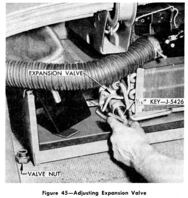
1953 Buick Adjusting Expansion Valve
If the expansion valve is acting as though it is out of adjustment by either starving the cooling coil of refrigerant or by flooding liquid into the low pressure line, it should be checked for proper adjustment.
If the expansion valve is open too wide, it may cause a frosting of the low pressure line and a higher than normal low pressure.
If the expansion valve is not open enough, the “low” pressure may be lower than normal and a partially charged cooling coil will result in lowered efficiency and partial cooling.
After removing the conditioning unit housing panels to gain access to the expansion valve, remove the 1″ hexagonal cap from the end of the expansion valve with a socket wrench being careful to give support to the valve with another wrench. This will prevent damage to the lines or valve mounting.
The expansion valve can best be adjusted by first closing the stem completely (clockwise) with the 3/16″ valve key and then opening it (counterclockwise) 9 complete turns. If this does not produce satisfactory operation it is suggested that the valve be replaced.
NOTE : Always replace the hexagonal cap after checking the setting.
- Replacing the Expansion Valve
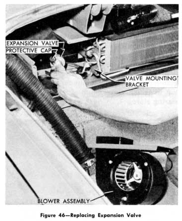
1953 Buick Replacing Expansion Valve
Before replacing the expansion valve, make certain the liquid inlet screen is not clogged. A discharged power element caused by a broken capillary line or broken tip is cause for replacement. A stuck shut or stuck open needle caused by corrosion is also reason for replacement.
In order to replace the valve :
- Remove the access plates from the cooling unit housing.
- Install the gage set and pump the system down as previously described.
- Disconnect the power element bulb from the suction line.
- For convenience, remove the left blower motor and assembly.
- Remove the equalizing, low pressure, and high pressure line flares in that order at the valve. Remove the valve clamp and valve.
- Install new valve by connecting the lines, clamp the power element to the low pressure Iine, then clamp the valve to the bracket.
- Crack the low pressure valve on the compressor and the high pressure valve on the receiver until full condenser pressure (about 35 pounds) is produced in the cooling unit. Then close both valves.
- Check the three newly made connections carefully for leaks.
- Evacuate the “low” side of the system as previously described.
- Open the “high” and “low” valves of the compressor and open the receiver valve.
- Replace blower-motor assembly.
- Replace the access plate and check the operation of the system.
- Operate the unit for 10 minutes at 1600-1700 R.P.M. and observe sight glass.
- Add refrigerant to replace that lost in the operation.
- Check and add compressor oil as necessary.
- Replacing Solenoid Valve
If the solenoid valve coil is open, shorted, grounded or burnt, it should be replaced.
If the valve fails to close and hold properly when energized, or fails to open when de energized, it will be necessary to replace the entire valve.
In order to replace it, proceed as follows:
- Connect the gage set to both gage connections on compressor. (Do not operate the compressor.)
- Close the hand shutoff valve at the receiver.
- Discharge the “high” and “low” sides of the system through the gage set, to a pressure of not more than 5 pounds. Because the hand shutoff at the receiver is closed and there is a check valve in the line from the condenser to the receiver, the refrigerant that is in the receiver will remain there. This is based on the supposition that the check valve is closing properly.
- Remove the bumper and grille assembly by disconnecting the six 3/4 inch nuts from the attaching bolts.
- Disconnect the wiring Ieads from the solenoid and remove the coil cover for access to flare nuts. Remove the solenoid valve from the Iine by disconnecting the flare nuts.
- Install a new solenoid valve, being certain that the direction of the arrow on the valve body is pointing in the correct direction for flow. Reconnect the wiring to the valve.
- Open the hand shutoff valve at the receiver. Allow the system to build up pressure between 35 and 40 pounds. Close the valve and test for leaks.
- If no leaks are found, leave the receiver valve closed and evacuate the system. Follow the instructions given in “Evacuating the En tire System,” with the exception of keeping the receiver valve closed in order to save the refrigerant in the receiver.
- Open the hand shutoff valve on the receiver and charge the system with refrigerant. Follow the instructions given in “Adding Refrigerant-Partial Charge.”
- Replace the bumper and grill assembly.
- Replacing the Dehydrator-Filter or Sight Glass
Since the dehydrator-filter and sight glass are both in the high pressure liquid line, the procedure for replacing either one will be nearly the same.
The dehydrator-filter should be replaced if it has been damaged through an accident, if there has been a complete loss of refrigerant, or any time the filter has been internally exposed to atmosphere more than 20 minutes.
If at any time when examining the compressor oil, moisture is found or there is an indication of moisture at the expansion valve need le, the dehydrator-filter should be replaced.
If a compressor fails during Operation and it is necessary to replace it according to the “Malfunctioning Compressor Procedure,” the dehydrator-filter should also be replaced.
In order to replace either the dehydrator filter or sight glass the following operations should be performed :
- Connect the “high” and “low” gages, vacuum pump, and cylinder to the compressor and purge the lines.
- Pump down the system as previously described.
- Disconnect the flare fittings at the dehydrator or sight glass and remove. (Prior to removing the sight glass, remove the bumper and grille assembly.)
NOTE : Do not uncap the new dehydrator until the exact time it is to be installed as it will quickly pick up moisture from the air and ruin its efficiency in the system. - Install the new dehydrator or sight glass making certain that the refrigerant flow through the dehydrator will be in the direction of the arrow on the label or the stamp “IN” on the inlet fitting.
- Evacuate to obtain a 26″ vacuum then shut off pump valve and pump.
- Apply sufficient drum pressure-30-40 pounds-to the “low” side to obtain a good leak test.
- Evacuate the “low” side to obtain a 26″ vacuum for 10 minutes with pump running. Shut off pump valve and pump.
- Open the compressor “high” and “low” valves and the valve at the receiver.
- Check the performance of the system and “charge” as necessary.
- Remove the processing and charging equipment and recap the gage connections.
- Check for the proper amount of compressor oil and replenish as necessary.
- Replacing the Shaft Seal
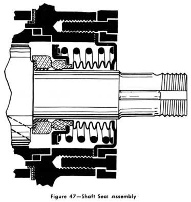
1953 Buick Shaft Seal Assembly
If a shaft seal leak has been found as a result of leak testing and diagnosing, a completely new seal should he installed.
The new seal assembly will be in a unit package, consisting of the bellows, Nitralloy and synthetic rubber seal and lead gasket. The lead gasket is to be positioned between the bellows flange and the boss on the compressor casting.
In opening the package and subsequent handling of the parts, use extreme care so as to avoid scratches, nicks or even finger printing the surfaces of the seal faces. Such care is necessary because these surfaces must prevent the leaking of the high pressure vapor.
In order to assure a satisfactory seal, it is important to follow carefully the procedure described below :
- With the car engine off, close the low and high pressure shutoff valves on the compressor.
- Use a gage adapter on the high pressure fitting and purge until the escaping vapor produces only a slight hiss.
- Remove the low and high pressure lines from the compressor.
- Loosen the generator mounting link and remove the compressor belts.
- Remove the compressor from the mounting brackets and move it to the work bench. Then remove the pulley.
CAUTION: Care should be exercised in re moving the pulley. Do not hammer it off the shaft but use a 2 jaw puller if necessary. - Remove the 6 studs from the seal retaining plate, then remove the plate and the bellows seal.
- Remove the Nitralloy ring from the shaft using the large end of the special seal tool J5425.
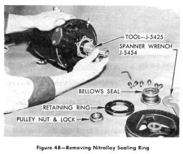
1953 Buick Removing Nitralloy Sealing Ring
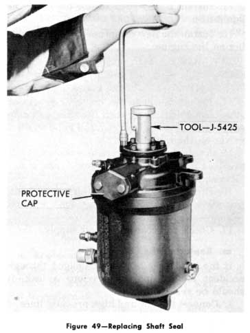
1953 Buick Replacing Shaft Seal
The bolts should be tightened alternately to insure even pressure against the seal. Do not remove the centering tool until all bolts are tight. Assemble the pulley and rotate the compressor by hand several times.
NOTE : Pulley is marked “Compressor Side.” Be sure this side is next to the compressor.
- Removal and Replacement of Compressor for “Engine Maintenance Only
Whenever it becomes necessary to perform certain operations on the right side of the engine, it will be necessary to remove the air conditioning compressor.
To gain access to the engine, the following steps should be taken :
- Shut off the high and low pressure valves at the compressor.
- Loosen the bolts on the hand shutoff valves on the compressor about %6″, then tap the valve to free it from the “0” ring and flange opening. The valve should come back firmly against the” bottom of holt heads.
- A momentary release of vapor should be expected as the “0” ring leaves the boss on the casting. lf vapor continues to escape, it would indicate one of two things; either the shut-off valve is not tight or the spring loaded automatic valve in the body is not seating properly.
In the latter case, it will be necessary to purge the compressor body at the high side gage connection, by use of a gage adapter or a suitable tool.
- Complete the removal of the attaching bolts and valves from the compressor. Protect the openings in the compressor and the hand shut-off valves. (Suggest use of aluminum foil.)
- Loosen the belts and remove the compressor to work bench.
- After making maintenance repairs on engine, reinstall the compressor.
- Leak test and correct as necessary.
NOTE: Upon reinstallation use new “0” rings and valve flange gaskets. Apply Frigidaire oil to the “0” rings and valve flange gaskets before fitting the valve into the opening sleeves in the compressor. This will permit easier installation.
CAUTION: Make sure all valves are open before starting engine.
- Removing a Malfunctioning Compressor and Installing a New Compressor
A malfunctioning compressor is one that will not turn over, has stuck divider blocks, broken discharge reeds or some internal difficulty which prevents the compressor from operating properly.
When such a difficulty is encountered, not only will the compressor need replacement, but additional processing of the system. will be necessary.
The procedure outlined here should be followed:
- Install the low pressure gage to the low pressure gage connection on the compressor. (Do not operate the engine or the compressor.)
- Close the high pressure hand shut-off valve at the compressor. Also close the high pressure hand shut-off valve at the receiver.
- Energize the solenoid valve. (Run a jumper wire from the “hot” terminal on the junction block to the valve.)
- Discharge the low pressure side of the system through the low pressure side of the gage set.
- Close the low pressure hand shut-off valve at the compressor.
- Disconnect the dehydrator-filter in the liquid line and remove.
- Disconnect the “low” gage from the compressor. Disconnect the high and low pressure valves from the compressor and remove the compressor from the mountings.
- Open wide the shut-off valve at the receiver and allow the refrigerant in the high side of the system to discharge at the connection where the dehydrator-filter was connected. (Place rags or a bucket at the end of the line where the dehydrator-filter was connected so that refrigerant and oil do not splash on the car or floor.)
NOTE: lf the system has been completely discharged of refrigerant because of the compressor difficulty, it is necessary to use liquid Freon-12 from a drum to do this flushing job. This can be accomplished by following these instructions:
- Close the high pressure line valve at the compressor.
- Energize the solenoid valve with a jumper wire.
- Remove the core from the self-closing valve installed in the header of the condenser.
- Install a charging line to this connection and to a Freon-12 drum, containing at least 5 pounds of Freon-12.
- Invert the drum and open the drum valve wide, allow approximately 5 pounds of the liquid Freon-12 to flush through the condenser, the receiver and out of the liquid line at the dehydrator.
- Close the drum valve and disconnect the charging line from the drum.
- Disconnect the charging line from the condenser fitting and replace the core in self-closing valve.
- De-energize the solenoid valve and remove the jumper wire.
- Remove the cone screen from the liquid inlet of the expansion valve and install a new cone screen in the valve.
- Install a new dehydrator-filter in the liquid line.
- Install the new compressor in the mounting on the engine.
- Install the high and low pressure hand shut-off valves on the compressor using new “0” rings and valve flange gaskets.
- Install the gage set on the compressor gage connections along with the vacuum pump and Freon cylinder, and open the hand shut-off valves on the compressor.
- Evacuate the system and leak-test as per previous instructions under service operations “Evacuating the System.”
- Recharge the system with refrigerant, per service operation “Adding Refrigerant-Complete Charge.”
- Check for compressor oil supply.
- Replacing the Condenser
If the condenser becomes damaged through accident or collision, or develops a leak, it should -be replaced.
- Connect the low and high pressure lines of the gage set to the low and high pressure gage connection on the compressor.
- Close the low pressure hand shut-off valve on the compressor and the high pressure hand shut-off valve at the receiver.
- Energize the solenoid valve. (Do not operate the engine or compressor.)
- Wear protective goggles and discharge the condenser through the high pressure side of the gage set. (The check valve should hold the refrigerant in the receiver.) Be sure the pressure in the condenser is discharged to below 5 pounds gage pressure. Close the compressor high pressure hand shut-off valve.
- Remove both horns and the lower hood latch-(scribe position of latch for reassembly). 6. Remove the bumper and grille assembly.
- Disconnect the condenser from the high pressure line flared connection at the condenser header, and from flared connection at the outlet of the condenser. (Cover open lines.)
- Remove the 8 Phillips head screws that attach the condenser to the side braces and Iift condenser up between grille frame and radiator.
- Install the new condenser by reversing the procedure used in Items 5-8.
- Evacuate the condenser and lines and recharge the refrigerant lost, following procedures previously described “Adding Refrigerant-Partial Charge.”
- Test for leaks and compressor oil supply.
- Replace the bumper and grille assembly.
- Replacing the Receiver
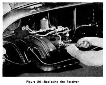
1953 Buick Replacing the Receiver
If the receiver develops a leak because of a collision or is damaged in any other way, it is best to replace it.
Since it is on the high pressure side of the system, the entire charge of refrigerant must be released to the atmosphere.
In order to replace the receiver, follow the steps listed here:
- Install the “high” and “low” sides of the gage set to the connections on compressor.
- Open the “high” side valve on the gage set and discharge vapor through the center connections. (Use goggles for the eyes and a cloth to absorb oil being discharged.) When the pressure is reduced to within readable range (under 100 pounds) on the low pressure gage, open the low side shut-off valve.
- Continue discharging until all refrigerant has been released, or the pressure does not exceed 5 pounds.
- Remove the bumper and grille assembly.
- Disconnect the high pressure inlet line flare at the receiver and protect end of line from moisture.
- Disconnect the high pressure Iine from the shut-off valve on the receiver and protect line.
- Remove the receiver mounting bolts and remove the receiver.
- Transfer the fittings from the old receiver to the new receiver.
- Install the new receiver by reversing the procedure for removing it.
- Evacuate the entire system and recharge with refrigerant as described in “Evacuating and Adding Refrigerant-Complete Charge.”
- Leak test all joints which have been disturbed.
- Replacing the Cooling Coil
The cooling coil is located in the conditioning unit housing on the shelf in the trunk compartment.
lf a leak develops in any of the tubes or solder joints, or if one becomes damaged, it should be replaced.
The succeeding step by step procedure should be followed:
- Pump down the system as previously described.
- Remove the 2 access covers to the conditioning unit housing.
- Disconnect all of the air ducts from the housing.
- Disconnect the blower motor Ieads.
- From underneath the car disconnect the 2 refrigerant line connections at the conditioning unit housing fittings, then remove the fittings. (Cover or plug ends of the lines to keep out moisture.)
- From under the car disconnect the 2 short rubber drain tubes from fittings on drain pan; then remove fittings.
- From under the car remove the four 1/2″ conditioning unit mounting bolts and remove the unit from the Iuggage compartment. (The one rear mounting holt is out of sight-above the frame cross member.)
- Disconnect expansion valve lines then disconnect valve from cooling coil.
- Remove top panel of housing and disconnect coil from front side of housing.
- Install the new coil by reversing the removal procedure.
- Evacuate the “low” side of the system.
- Add refrigerant and compressor oil to re- place that lost in pumping down the system.
- Test for leaks and repair as necessary.
- Replacing a Blower Motor
If one (or both) of the fan motors fail to operate and it has been determined that the motor is defective, replacement is necessary.
To replace blower motors proceed as follows:
- Remove the 2 access covers to the conditioning unit housing.
- Disconnect the electrical Iead to the blower motor.
- Remove the metal strap which secures the rubber outlet tube to the blower duct.
- Remove the screws which hold the blower assembly to the conditioning unit housing and remove the blower assembly.
- Remove the motor and blower from the duct.
- Remove the blower from the motor shaft and install it on the new motor, making certain that the blower is in the corresponding position on the new shaft.
- Install the new motor and its assembly by reversing the removal procedure.
- Check motor and blower for proper operation.
- Replacing the Relay
In replacing the relay the following steps must be performed :
- Disconnect the terminals of the four wires leading into the relay box. The box is located in back of the instrument panel directly behind the temperature control switch.
- Remove the “High” – “Low” temperature control knob at the instrument panel.
- Remove the lock nut which secures the relay control shaft to the instrument panel.
- Remove the relay with its case.
- Reverse the removal procedure in replacing the relay.
- Replacing the Thermostat
The thermostat is replaced in the following manner:
- Loosen the clamp which secures the left outside air inlet tube to the metal elbow on the conditioning unit housing.
- Disconnect the terminals of the three wires leading into the end of the thermostat (located just beneath the filter in the left air return duct of the conditioning unit housing).
- Remove the metal elbow of the left outside air inlet tube from the conditioning unit housing.
- Disconnect the thermostat from its two clips and remove through the inlet elbow opening in the housing.
- Reverse the removal procedure in replacing the thermostat making certain to connect wires properly.
- Replacing the Check Valve
If it becomes necessary to replace the check valve because of external damage or leaks, proceed as follows:
- Install the “high” and “low” pressure gages to the compressor.
- Open the “high” gage valve and discharge all of the refrigerant. Use goggles to protect the eyes and a cloth to catch the oil at the discharge line.
- When pressure on “low” side is reduced below 100 pounds, open the “low” gage and discharge entire refrigerant.
- Remove the bumper and grille assembly.
- As the check valve is sweated onto its attaching lines it will be necessary to remove the valve with the lines at the receiver, solenoid bypass valve and condenser.
- Because the trouble with this valve is most probably a leak by the seat, disassemble the valve and inspect. If the seat is worn, replace with a new one and a new copper sealing ring, then reassemble.
NOTE: It will be necessary to slightly bend the tubing in order to disassemble the valve accordingly be careful not to dent the tubing. - If the check valve cannot be repaired, re place it, along with the attaching lines, as an assembly.
- After replacement of the check valve, the system must be evacuated and recharged.
- Check compressor for proper amount of lubricating oil and replenish as necessary.
- Replace the bumper and grille assembly.

Leave A Comment
You must be logged in to post a comment.