Diagnosis of Air Conditioner Service Problems is always associated with trouble. For example, if you went to a doctor, he would probably ask you what your trouble is. Realizing that your trouble might be caused by more than one condition in your system, he will proceed to make a diagnosis with various instruments and procedures to reach a conclusion as to the cause of your difficulty by the process of elimination. This same situation is often true in mechanical refrigeration. While some ailments are well defined, the cause of others is more difficult to locate and determine.
The following diagnosis procedure outlines the method for diagnosing the complaint, but does not involve the replacement or repair of the faulty condition. Replacement and repair will be discussed later when we take up the proper procedure for replacement and repair of the various parts of the system.
When diagnosing troubles, directly involving circulation and proper action of the refrigerant, checks must be made with the car engine running at approximately 1600-1700 R.P.M. or 35 to 40 mph road speed and the control switch “On,” unless otherwise indicated.
It is believed that so far as the air conditioning system is concerned there will be only four common complaints. In analyzing these mal functions, the analysis should be based on air conditioning standards for the car. The first of these will be: Blowers operating-no cooling.
Blowers Operating – No Cooling
- The first and easiest check is to determine whether the solenoid by-pass valve is open. This can be determined by feeling the temperature of the by-pass line on both sides of the valve. lf the valve is open, the by-pass line between the valve and the low pressure line should be considerably cooler than on the opposite side. If closed, the lines on both sides of the solenoid valve should be approximately the same temperature.
- If the solenoid valve is closed, the next check is to determine whether a decided short age of refrigerant is the cause of the difficulty. To determine this, remove the cap from the sight glass and, if you find it full of foam or you see no liquid at all, you have determined that there is a shortage of refrigerant, which indicates a leak in the system. One of the first and most important places to test for a leak is at the compressor shaft s al. This, as well as all other leak checks, should be made with the leak detector. Since the seal is on the high pressure side of the system, a leak at this point will result not only in the loss of refrigerant, but also of the vital lubricating oil in the compressor. lf the leak is large enough or continues too long, the result will be a stuck compressor. If the compressor sticks, the belts will wear excessively and soon break. This will result in the compressor becoming inoperative. The remedy for this and other conditions discussed during Service Diagnosis will be covered later in detail. If the solenoid valve will not close and the refrigerant supply is apparently normal, check the temperature control circuits.
Temperature Control Circuits
- If the refrigerant supply is apparently normal, the next step is to check for a blown relay fuse, which would cause the relay contacts to be open. Also the relay contacts may be open due to a mercury column separation in the thermostat or dirty relay contacts. Of course, when the relay contacts are open, the solenoid coil is not energized and the by-pass is open. This prevents the system from cooling even though the control switch is “ON” and the blowers are operating. If the thermo stat and relay are found to be all right, it will be necessary to check for short, grounded or open circuits.
- Check the Refrigeration System for Restrictions (Chart A.C.-2) : If a check of the electrical control circuit did not reveal the difficulty, check the refrigeration system for restrictions. In order to check for restrictions in the system, connect the high and low pres sure side of the gage set to the gage connections on the compressor. Note the operating pres sure with engine running for ten minutes at approximately 1600- 1700 R.P.M. and control switch “ON.” If the gage reading is lower than normal (20- 55 lbs.) on the low side, (a high reading is covered later when we discuss “Partial Cooling”) it indicates a restriction between the liquid outlet at the receiver and the Iow pressure side of the system through the compressor. This restriction may be caused by one of the following: Partially closed high pressure valve on the receiver, kinked or pinched high or Iow pressure refrigerant lines, clogged de hydrator-filter, dirty or clogged expansion valve inlet screen, expansion valve stuck shut, a partially closed low pressure hand shutoff valve at the compressor or a clogged filter in the compressor. A restriction at these points will be indicated by the presence of ice or frost at the point of restriction, with the exception of a stuck-shut expansion valve, partially closed low pressure shut off valve at the compressor or a clogged filter in the compressor.
- Check the Compressor for Stuck Divider Blocks: To check this condition, remove the compressor belts and rotate the pulley by hand one complete revolution, noting that every 180° offers a resistance to turning. Rotate the pulley one complete revolution in the reverse direction, again noting a resistance to turning every 180° The absence of resistance to turning at any point checked indicates a stuck divider block or possibly a broken high pressure discharge valve reed in the compressor.
Blowers Operating – Partial Cooling
- First check for a shortage of refrigerant at the sight glass, indicated by bubbles in the refrigerant. A slight shortage of refrigerant results in the cooling coil getting only enough refrigerant to do a partial job of cooling.
- If the refrigerant supply appears normal, check the solenoid by-pass valve for a leak past the valve seat. This check can be made by feeling the line entering and leaving the solenoid valve. If there is a leak past the valve seat there will be a definite difference in temperature between the inlet and outlet lines of the valve. The leak past the seat may be caused by some foreign matter on the seat and may possibly be dislodged by opening and closing the “ON – OFF” control switch. Otherwise the valve must be replaced.
If the refrigerant supply appears normal and the solenoid by-pass is okay, the difficulty may be due to the compressor working against a higher than normal “high” side pressure. Any condition that increases the normal “high side” pressure, greatly reduces the ability of the compressor to remove the required amount of heated vapor from the cooling coil and pro duce the desired cooling effect, so:
- Check high side operating pressure (Chart A.C.-2):
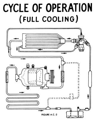
1953 Buick Cycle of Operation – Full Cooling
Check the high side pressure by noting the high pressure gage reading at engine speed of approximately 1600-1700 R.P.M. If the reading is higher than normal (110- 250 lbs.), it could be caused by one of the following:
- Above normal engine temperature.
- Restricted air flow through the condenser.
- Overcharge of refrigerant.
- Air in the system.
The first item, “A,” can be easily corrected by normal engine maintenance.
Item “B” – This can be corrected by using a stiff brush, compressed air or water to clean the condenser. Steam should not be used to clean it because it will cause excessive internal pressure. No doubt you are wondering how either of these conditions can cause high operating pressure. For instance, a shortage of water will cause the radiator and engine to overheat and increases the heat radiated from the radiator and engine to the condenser and compressor. This in turn increases the temperature of the condenser and compressor and raises the temperature and pressure of the refrigerant inside of them. In the other instance, a dirty or clogged condenser does the same thing to the refrigerant temperature inside of it as blocking the air flow over a radiator does to the water temperature. Again, this increase of refrigerant temperature also increases the pressure.
Item “C” – If the high side pressure is still high with the engine temperature condition corrected and the condenser is clean, the trouble may be caused by an overcharge of refrigerant. The high pressure is caused by too much of the condenser being occupied by liquid. This reduces the amount of condensing space and surface to such an extent that the heat cannot be dissipated as rapidly as it should, thus the in crease in pressure. The excessive amount of refrigerant should be discharged until the operating high pressure is reduced to normal.
Item “D” – Air in the system produces the same symptoms as an overcharge of refrigerant. No matter where or how air enters, it ends up in the condenser and compressor. Air, in a system such as this, is considered to be a noncondensible gas. Therefore, it mixes with the refrigerant vapor in the condenser and occupies valuable condensing space.
The method of checking for either of these last two conditions will be covered in the “Servicing Operations” for “Purging Air and/or Excessive Refrigerant from the System.”
From the preceding discussion, we can see how important it is to have proper engine temperature, a clean condenser, the right amount of refrigerant, and to keep air out of the system.
- Check the expansion valve : If all of the foregoing checks have not located the cause of the difficulty, check the expansion valve for proper adjustment. An expansion valve that is open too wide, allows more refrigerant to enter the cooling coil than it can hold, so the excess liquid enters the low pressure line. If the excess liquid is enough to prevent the compressor from reducing the pressure in the cooling coil, the temperature of the coil and passenger compartment will both be increased proportionately, A valve that is not open wide enough may be the result of improper adjustment, discharged power element, or an improperly clamped and insulated valve thermo-bulb. The proper adjustment is ten turns open from the fully closed position.
The next complaint that we want to discuss is the conditioning unit being too cool.
Too Cold
This complaint can be caused by the failure of the by-pass solenoid valve to open, so let’s Iook at a schematic wiring diagram of the temperature control circuit.
If the by-pass solenoid fails to open when a warmer temperature is called for, this may be caused by the solenoid plunger being stuck closed, relay contacts stuck closed or a faulty thermostat.
Blowers Not Operating
The steps in diagnosis involves checking the electrical circuit for the blowers.
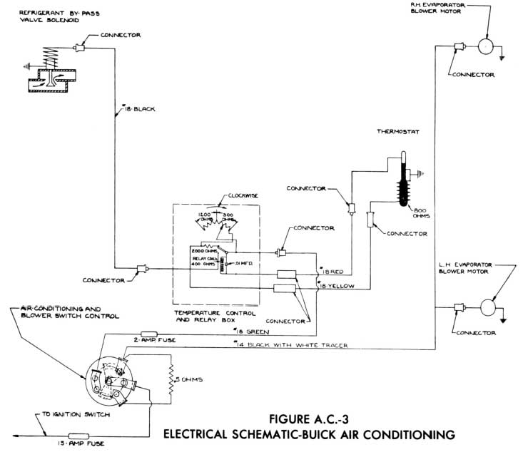
1953 Buick Air Conditioning Electrical Schematic
This includes the fuse, control switch, the wiring and the terminals. Let’s take a Iook at the blower circuits.
This illustrates the electrical circuit for the blowers. If neither blower is Operating, the cause can be a blown fuse, or a broken wire or a loose terminal between the ignition switch and the common terminal of the blower motors. Also the contacts or mechanism in the control switch could be faulty. By point-to-point checks and visual inspection of the terminals, the difficulty can be easily located.
If one blower will not operate, the difficulty could be stuck motor bearings, electrical failure inside the motor, a broken wire leading to the motor, a loose terminal, worn brushes or commutator, or faulty control.

Leave A Comment
You must be logged in to post a comment.