In any vocation or trade, whether it is plumbing, electrical work, carpentry, or car repairing, there are always certain factors that re quire special attention or handling. There are established procedures for doing things that are considered good practices. There are occupational hazards in any vocation or trade requiring mechanical skill and the use of special tools. Servicing air conditioning equipment, also, has its special requirements, tools and hazards. However, learning to observe the three “P.’s”-Procedures, Practice, and Precautions, that have been established after many years of experience will greatly reduce the possibilities of damage to your customer’s equipment, and to yourself.
PRECAUTIONS IN HANDLING FREON-12
- Do not Leave Drum Uncapped
- Do not Carry Drum in the Passenger Compartment of Car
- Do not Subject Drum to High Temperature
- Do not Fill Drum Completely
- Do not Discharge into Areas Having Exposed Flame
- Do not Expose the Eyes to Liquid
The first procedure we want to discuss is:
1953 Buick Air Conditioner Precautions In Handling Lines
You may be required to replace all or portions of the refrigerant lines. The lines that you use should come out of your stock completely sealed and dehydrated.
The lines should be free of kinks, because of the restriction that the kink will offer to the flow of refrigerant. The refrigeration capacity of the entire system can be greatly reduced by a single kink in any line.
Inasmuch as the high and low pressure lines are installed close together, tubing clamps are used and should be replaced if removed. The clamps keep the tubing separated which reduces vibration and the possibility of damage to the tubing.
The use of the proper wrenches when making flare connections is important. lf the wrench is too short, the flare may not be seated tight enough and a leak might develop. lf the wrench is too long and heavy, the flare may be seated too tight. Remember, the copper flares are relatively soft and double in thickness, consequently a great amount of pressure against the seat is not required. The opposing fit ting should always be backed up with a wrench to prevent distortion of connecting lines or components.
When making flare line connections it is recommended to apply a small amount of Frigidaire oil to the back of the line flare and mating surface on the nut in order to prevent galling and possible twisting of the line.
MAINTAINING CHEMICAL STABILITY IN THE REFRIGERATION SYSTEM
- Keep Tubing Capped
- Keep Tools Clean
- Keep Gage Set Capped
- Keep Replacement Parts Clean and Dry
- Use Clean, Dry Container When Adding Oil
- Keep Oil Container Capped
- Do not Keep System Open Longer than necessary
- Use Vacuum Pump After Performing Service Operations
Maintaining Chemical Stability in The Refrigeration System
Whenever it becomes necessary to disconnect a refrigerant line, it should be immediately capped with a flare plug, or tape-depending on the type of connection. lt must be remembered that all air contains moisture. Air that enters any part of the system will carry the moisture with it and the exposed surfaces will collect the moisture quickly. Capping the tubing will also prevent dirt and foreign matter from entering.
Tools should also be kept clean and dry. This also includes the gage set and replacement parts.
When adding oil; the container should be exceptionally clean and dry due to the fact that the oil in the container reaches you as moisture- free as it is possible to make it. Therefore, it will quickly absorb any moisture with which it comes in contact. For this same reason the oil container should not be opened until ready for use and then it should be capped immediately after use.
When it is necessary to open a system, have everything you will need ready and handy so that as little time as possible will be required to perform the Operation. Don’t leave the sys tem open any Ionger than is necessary.
Finally, after the operation has been completed and the system sealed again, a vacuum pump should be used to remove any air that might have entered. This procedure will be explained later in the program.
Gage Set
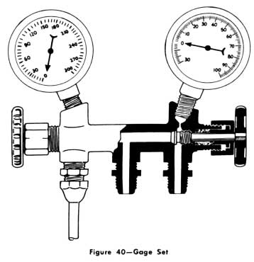
1953 Buick Gage Set
The gage set consists of a brass manifold equipped with two hand shutoff valves and five 1/4″ female pipe openings. The side having the two openings accommodates pressure gages. The other 1/4″ pipe and 1/4″ flare connections are for attaching lines.
The gage at your right is known as the low pressure gage. The face is graduated into pounds of pressure from 0 to 100 and, in the opposite direction, in inches of vacuum from 0 to 30 inches. This is the gage that should al- ways be used in checking pressures on the low pressure side of the system. When all parts of the system are functioning properly the refrigerant pressure on the low pressure side never gets below 0 pounds pressure. However, abnormal conditions can occur that will cause the low pressure to get down into a partial vacuum. Therefore, a low pressure gage is required.
The other gage is graduated from 0 to 300 pounds pressure in 5 pound graduations. This is known as the high pressure gage and, of course is used for checking pressures on the high pressure side of the system.
The connection on your right is for attaching the low pressure gage line; the one on your left the high pressure gage line. The center connector is common to both and is for the purpose of attaching a line for adding refrigerant, discharging refrigerant and other uses. When this connection is not required, it should be capped with a 1,4″ flare nut and cap.
The hand shutoff valves do not, at any time, have anything to do with opening or closing off pressure to the gages. They merely close each opening to the center connector and to each other. During most diagnosing and service operations, the valves must be closed. The only occasion for opening both at the same time would be to by-pass refrigerant vapor from the high pressure to the low pressure side of the system, or in evacuating both sides of the system.
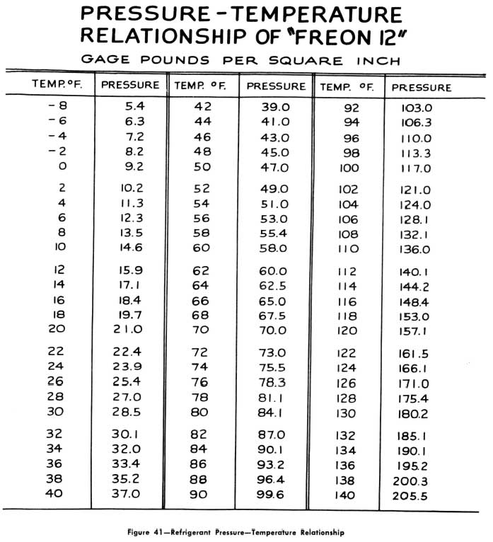
Refrigerant Pressure-Temperature Relationship
Without a basic knowledge of the Pressure Temperature Relationship, it would be impossible for you to make the proper diagnosis of certain difficulties which may occur in the system.
The figures on this chart apply only to Freon-12. Each kind of refrigerant has a different pressure-temperature relationship.
The chart shows us that every time we raise or lower the temperature of a confined quantity of Freon-12, we also raise or lower the pressure on it. Unfortunately this is not done in the same ratio. For example, at 70° the chart shows that the pressure is also 70 pounds. But this is true only at 70° However, if we know the temperature of the liquid in the cooling coil or the receiver, we can refer to a pressure-temperature table and determine what the pressure should be.
The figures can also be used in a reverse manner. If we know what the pressure is at any point in the system we can refer to the pressure-temperature table and determine what the temperature should be.
1953 Buick Air Conditioner Pressure Temperature Relationship

Leave A Comment
You must be logged in to post a comment.