Conditioning Unit
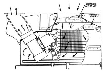
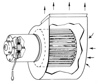
Here we see a cutaway view of the conditioning unit. It is mounted to the shelf in the trunk compartment of the car with 4 bolts and connected to the condensing unit by tubes. Also, ducts are connected to the conditioning unit and package shelf of the car for the handling of air to and from the car interior. It illustrates the relative position of the components. It also illustrates the air circulation in and out of the unit.
Air Ducts
The ducts for conditioned air are made of heavy grade rubberized cloth. Each is connected to a grille located at each end of the package shelf.
1953 Buick Air Conditioning Unit
The return air ducts are made of the same material as the conditioned air ducts and are connected to grilles located near the center of the package shelf. Air filters are placed in the return air ducts.
The two “outside air” ducts are made of flexible tubing and each extends to a metal air scoop located on each side of the car. Each tube has a manually operated damper. Controls are located inside of the trunk compartment on the ducts. During summer Operation these valves remain open at all times. It is recommended they be closed during the winter months.
Condensate Drain Pan
The drain pan is made of copper and it covers the bottom of the housing interior. Its purpose is to catch the water which has been formed by the condensation of moisture on the cooling coil surface and that which enters through the outside air ducts.
The drain pan has two outlets which extend through the shelf of the Iuggage compartment permitting the moisture to drop to the road.
Now let’s consider the construction of the housing.
Housing
The housing shell is made of rustproof steel, painted with grey enamel. Removable panels are provided for disassembling the housing when a coil replacement is required. Two access panels are located on the rear of the housing for gaining access, for adjusting or replacing the expansion valve.
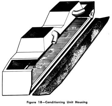
1953 Buick Air Conditioning Unit Housing
Internally the housing is lined with “Rubatex”‘ insulation. The purpose of the insulation is threefold. First, it retards the flow of hot or warm air from the Iuggage compartment into the conditioning unit, thus reducing the refrigeration Ioad on the cooling coil. Second, it prevents the outer surface of the housing from sweating or frosting during the operation of the system. Third, it absorbs sound for quiet operation.
NOTE : Bottom insulation is 1,4″ thick and the side is 1/2” thick.
Cooling Coil
The cooling coil may be described as a container for refrigerant liquid and is so designed that it can readily remove heat from the surrounding area after the temperature of the refrigerant liquid is reduced. It is the only place in the system where the refrigerant is changed from a liquid to a vaporous state. This is done by the absorption of heat.
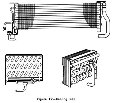
1953 Buick Cooling Coil
The coil is made of 3/8″ copper tubes and aluminum fins. The fins are spaced closely together so as to provide maximum cooling surface for picking up heat. The coil has a distributor and metering tubes or a manifold with metering orifices that insure an even supply of liquid refrigerant to all parts of the coil similar to a car manifold. It is a “multipath” coil made up of tubes connected in series and joined together by a distributor or manifold at the inlet and by a manifold at outlet, thus forming parallel paths of flow. The coil is sup ported in the housing by rust proof brackets.
Every refrigerating system requires a refrigerant control of some type. There are several types in use, each adapted to specific applications. Regardless of type of application, a refrigerant control valve has only one purpose and that is to regulate the supply of liquid refrigerant according to the requirement of the cooling coil. Expressed differently, it supplies liquid refrigerant to the cooling coil at the same rate that vaporous refrigerant is removed from it. Thus, if the valve is properly adjusted and is operating normally, it will maintain the right amount of liquid in the coil at all times. Basically, a refrigerant control valve can be com pared to the carburetor on a car.
This system employs a thermostatic expansion valve to control the refrigerant. As its name implies, the valve is controlled by temperature changes at the point where the bulb is attached to the low pressure line. It has nothing to do with controlling the temperature in the car. The temperature in the car is controlled by another component which will be explained later.
Thermostatic Expansion Valve
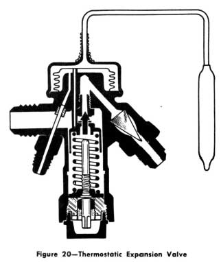
1953 Buick Thermostatic Expansion Valve
Here is a cutaway view showing the various parts. They are the power element, the body, the operating pins (3 in number) the stationary seat, orifice, needle carriage, adjusting spring and stem. At the high pressure inlet is a fine mesh screen which prevents dirt, filings or other foreign matter from entering the valve orifice. This small connection and tube is called an equalizing connection.
When connected in the system, the high pressure liquid enters the valve through the screen and passes on to the needle orifice. The low pressure liquid leaves the orifice and flows into the coil. The power element bulb is clamped to the low pressure line just beyond the outlet of the cooling coil
The operation of the valve is quite simple. lt is a matter of controlling opposing pressures produced by a spring and refrigerant pressures. For example; the pressure in the power element is trying to push the needle away from the seat, the adjusting spring is trying to force the needle toward the seat. When the system is not in operation; the refrigerant pressure in the cooling coil is helping the adjusting spring to close the valve. These opposing pressures are established in the design of the valve so that during idle periods the adjusting spring tension and the refrigerant pressure in the cooling coil is always greater than the opposing pressure in the power element. Therefore, the valve re mains closed. This means that the only way the valve can be opened, in this particular system, is to turn the switch at the control panel to the “ON” position so that the compressor can re duce the pressure and temperature of the refrigerant in the cooling coil. When this pressure is reduced to a point where the vapor pressure in the power element becomes the stronger, the needle moves off the seat and liquid starts to flow through the valve orifice into the cooling coil. As long as the switch on the control panel is “ON”, the thermostat calling for refrigeration, and the compressor in operation, the valve will never close and completely shut off the supply of liquid.
No doubt you are wondering about the purpose of the power element. lts duty is to help determine the quantity of liquid that is being metered into the cooling coil. As the temperature of the low pressure line changes at the bulb, the pressure of the vapor in the power element changes resulting in a change of the position of the valve needle. For example, if the cooling coil gets more liquid than is required, the temperature of the low pressure line is reduced and the resultant lowering of the bulb temperature reduces the pressure of the vapor in the power element allowing the needle to move closer to the seat. This immediately reduces the amount of liquid leaving the valve. Under normal operation, the power element provides accurate control of the quantity of refrigerant to the cooling coil.
The equalizing feature is required in all high capacity systems. lt provides the same pressure in the area opposite the power element as that in the cooling coil. This further helps to keep the cooling unit adequately supplied with liquid refrigerant.
The adjusting stem performs the same function as the idling screw adjustment on a carburetor. Turning the stem counterclockwise in creases the flow; clockwise decreases it. Its setting is determined by the size of the cooling coil and in any system there is only one proper setting. All air conditioning systems utilize fans or blowers to produce air circulation. As previously mentioned, this system has two. Let’s discuss the 1953 Buick Air Conditioner construction and operation of the blowers.
Blowers
Each blower assembly consists of a blower and a small motor. The blower is the centrifugal type which is best suited for the purpose. lt is commonly called the squirrel cage type.
1953 Buick Cooling Unit Motor and Blower
Each blower wheel is encased in its own housing which insures the proper flow of air from the refrigerated area to the ducts leading to the car interior.
Each blower wheel is driven by a fractional horsepower, 12 volt, brush-commutator type motor. They are 1/30 hp and have a speed of approximately 2000-2100 RPM. One rotates clockwise and one counterclockwise and will operate within a range of 9 to 16 volts. Each draws 5 AMPS. They are similar in construction to the heater motors with which you are familiar. At full speed, each blower has a capacity of moving 150 cubic feet of air per minute.
Condensing Components
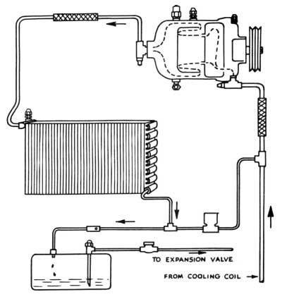
1953 Buick Schematic of Condensing Unit
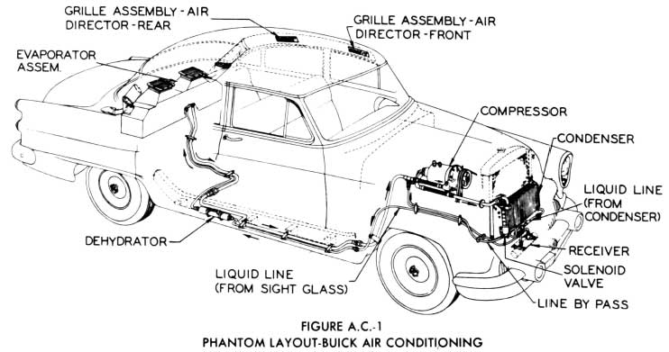
Here we have a schematic drawing showing the three major components, located in the engine compartment namely the compressor, con denser and receiver. Also shown is the refrigerant by-pass solenoid valve, the refrigerant check valve, the liquid refrigerant sight glass, the vibration eliminators and the connecting refrigerant lines located in the engine compartment.
At this time we would Iike to point out the three hand shutoff refrigerant valves in the entire system. Two of these are on the compressor and the other is on the receiver.
The first component we want to discuss is the compressor. This unit obtains its prime moving force from the engine through pulleys and 2 belts. Its purpose and action is somewhat similar to that of an air compressor. We know that the head of the compressor and the high pressure discharge Iine gets hot. One of Nature’s laws comes into effect in this situation-“When a vapor is compressed both its temperature and pressure are raised.” In the case of an air compressor, the prime purpose is to increase the pressure so that its force can be put to a practical use. In a refrigeration compressor, the prime purpose is to increase the refrigerant vapor temperature so that it can be changed back into a liquid again. At the point of compression, this temperature may be considerably higher than that of the condensing medium, which is the air that passes through the condenser. Since nature says that we can’t have this increase in temperature without automatically having a decided increase in pressure, we put that law to a practical use. This we will talk about later.
Now that we know the purpose of the compressor, let’s become familiar with its construction.
Cutaway of Compressor
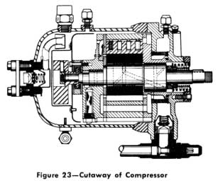
1953 Buick Cutaway of Compressor
This chart illustrates a type of compressor that is known as a rotary type. It has several advantages over the reciprocating type compressor, especially as applied to our use. lt is small in size, has few moving parts and is high in efficiency.
The major parts which we want to point out are the housing and head, the eccentric shaft, the pulley which turns it, the stuffing box or shaft seal, the roller, the two spring-loaded divider blocks and the oil pump.
Some of the other internal parts are the low pressure port and its self-closing valve, low pressure vapor filter, the oil intake tube and screen, the counter-balance, oil separator, and the high pressure port and its self-closing valve. Externally, we see the high pressure relief valve, high pressure gage connection, the oil Ievel test elbow, the low pressure shutoff valve and the low pressure gage connection. Due to the actual position of a few of these parts, some liberty has been taken in the drawing for sake of clarity.
At this time we would like to explain briefly the purpose of some of the parts of the compressor.
The shaft seal prevents refrigerant vapor and oil from escaping to the atmosphere while providing a stationary seat against which the shaft can turn. Until further notice, this is the only internal part of the compressor that we recommend be replaced in the field. We will discuss the construction and replacement of this later in the program.
The roller serves the same purpose as a piston in a reciprocating pump. The two divider blocks are kept in constant contact with the roller by spring tension. This contact, plus a thin film of oil, prevents the vapor from getting out of the compression chamber during compression, thus acting similar to piston rings.
The oil pump is of the rotary type. The action of the oil pump is the same in principle as the compressor. The only difference is that the oil pump creates oil pressure while the compressor creates vapor pressure.
The self-closing valves in the low pressure and high pressure ports have a spring loaded seat that closes when the hand shutoff valves are removed for any reason.
NOTE : These hand shutoff valves are so constructed that when the valve body is bolted to the compressor housing, the hand valve de presses the spring loaded valve in the housing. This opens the housing valve seat in the compressor. When the valve body is removed from the compressor, the compressor housing valve closes.
This prevents the loss of refrigerant and oil, and helps to prevent dirt and moisture from the air entering the compressor when the compressor is removed for any reason. The oil Ievel assembly is an elbow containing a Schrader type valve screwed in to the bottom of the compressor housing. It is provided for the purpose of checking the oil Ievel.
Now, let’s follow the path of refrigerant and oil through the compressor while it is operating.
The low pressure vapor from the cooling coil and low pressure line enters the low pressure valve and port into the chamber in the compressor head. It passes through the filter and enters the compression chambers. As the shaft eccentric causes the roller to move, the vapor is squeezed into a very small space which com presses it to a high temperature and pressure. The high pressure vapor which discharges from the discharge valves is directed against the metal baffle and then into the high pressure chamber of the housing. From the housing the vapor passes through the oil separator and into the high pressure shutoff valve and high pres- sure line. In passing through the oil separator, much of the oil is retained in the housing.
While one compression chamber is compressing its vapor, the other chamber is taking on a new supply from the low pressure cavity.
Due to the location of some of the oil passages, the exact flow of oil cannot be illustrated. How ever, as the eccentric shaft turns, oil is drawn from the bottom of the housing through the fine mesh screen into the oil pump. lt is then forced into the oil cavity and from there it is forced through a port of the shaft seal housing. From there some of it is forced into the drilled pas sages in the shaft to the front bearing and the roller. The excess oil flows through the back pressure relief valve into the oil reservoir which is also the lower part of the housing.
From our discussion of the compressor so far, we have pointed out that two different pressures are maintained during the operation of the system; High pressure and Low pressure. If the High pressure gets too high or the Low pressure gets too low, something is wrong and must be corrected. Later in the program, when we discuss Service Diagnosis, we will cover the subject of gages and how these pressures can be interpreted.
Gage Connection
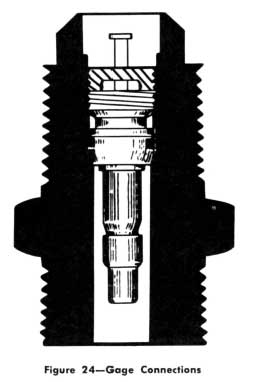
1953 Buick Gage Connections
The compressor gage connections for determining both the high and low pressures are identical in construction, as illustrated here. They are known as the self-closing type. The core is a Schrader type valve. The body of the valve is steel and the threaded ends are a 1/4″ flare connection and a 1/8″ pipe thread. Each is equipped with a 1/4″ flare and cap which is removed before taking gage readings. Also, before gage readings can be obtained a 1/4″ gage line must be equipped with an adapter.
Adapter
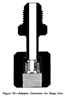
1953 Buick Adapter Connector for Gage Line
This adapter performs the same function and operates in the same manner as the fitting on the end of an air hose when putting air in a tire. As the knurled nut is turned, the rubber like material seals against the connector just before the core pushes against the valve stem. The 1,4,” flare connection is for installing to the gage line.
High Pressure Relief Valve
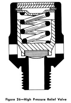
1953 Buick High Pressure Relief Valve
This valve, like any other of its type, is put into the system as a safety factor. Under certain circumstances, the refrigerant pressure on the high pressure side may exceed a safe Operating pressure. Therefore, to prevent damage to the equipment or the car, the valve is de signed to open automatically at approximately
375 pounds pressure per square inch and to close automatically when the pressure is reduced to approximately 350 pounds pressure per square inch. Any condition that causes this valve to open should be corrected.
Refrigerant Condenser
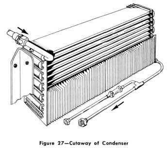
1953 Buick Cutaway of Condenser
As the name implies, this part condenses the high pressure refrigerant vapor that is discharged from the compressor. You are all familiar with the condensation of water vapor which frequently takes place in gasoline tanks and crankcases of cars when the outside temperature is reduced. This may be compared to the change of vapor-to-liquid that takes place inside of a refrigerant condenser. The high pressure, high temperature vapor produced by the compressor is subjected to considerably cooler metal surfaces and a change of the refrigerant state takes place. This is based on two well known laws of nature. The first law states that heat always travels from the warmer to the cooler substance. The second states that when enough heat is removed from a vapor, liquid is produced. In fact, when enough heat is removed from a liquid, a solid is produced. Steam, water, and ice are good examples.
Since the advent of mechanical refrigeration and air conditioning, condensers of many sizes, shapes and arrangements have been designed for various applications. There are two factors that have to be considered in the design of any condenser-the metal of which it is made and the amount of effective condensing surface it has. So let’s discuss briefly the construction of our condenser.
It is constructed of steel and hydrogen brazed. After assembly the complete unit is Iead dipped and black enameled. It is of the plate and fin type. The plates are formed to have internal fin and pass construction. They are joined at each end by headers except at the inlet plate and the outlet plate. The headers are welded to the plate in a manner so that the flow of high pressure refrigerant vapor flows through the top plate from the inlet manifold and parallel with the inside fins of the plate header. The header then directs the flow in the opposite direction through the next plate, and this continues through the condenser to the outlet manifold. The outside fins are spaced very close together for efficient heat dissipation. The mounting brackets are bolted to studs welded in the headers on each side. The inlet manifold connection on the condenser is a 5/8″ flare. The outlet manifold connection is a 3/8″ flare. The refrigerant flow through this condenser is known as parallel-series flow. The condenser inlet manifold is equipped with a self-closing valve for the purpose of charging the system with liquid refrigerant at the assembly plant. It is identical in construction to the high and low pressure gage Connections on the compressor, previously described. It must be tightly capped with a 1/4″ flare nut cap. At present it is not intended for use in diagnosing. After the liquid is produced in the condenser, we have to have some place to put it for the condenser to continue its work. This system like most systems uses a liquid refrigerant receiver.
Liquid Refrigerant Receiver
The receiver stores the liquid refrigerant and maintains a supply which is more than that needed for normal operation.
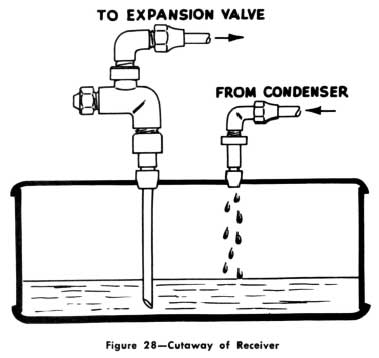
1953 Buick Cutaway of Receiver
A better understanding of this component can be had by looking at the cutaway. The receiver is made of a heavy gage steel tube, with the end plates brazed in at each end. As previously mentioned, the receiver is equipped with a hand shutoff valve. A tube extends from the valve to within a short distance of the bottom. As long as the amount of liquid is enough to cover the bottom of the tube, the sys tem can operate normally. The high pressure produced by the compressor is also maintained on top of the liquid. This keeps the liquid from refrigerating in the receiver and also causes the liquid to be forced back to the expansion valve.
Having completed our discussion of the three major components of the condensing unit, let’s learn more about the other items.
Refrigerant By-Pass Solenoid Valve
The valve and by-pass Iine play an important role in the Operation of the refrigeration sys tem. When the outside weather is comfortable and no air conditioning is desired, some means must be provided to prevent the compressor from lowering the pressure and temperature in the cooling unit. (lt must be remembered that the compressor operates whenever the engine is running.) When the by-pass valve is open, the compressor cannot reduce the pressure in the cooling coil due to the fact that there is no seal between the high and Iow pressure sides of the system. Therefore, the cooling coil temperature remains high. When the valve is closed, the system can resume normal operation.
We’re sure all of you are familiar with a solenoid, since they are used in electrical circuits for starting cars. However, let’s take a Iook at a chart illustrating a cutaway of a solenoid by-pass valve.
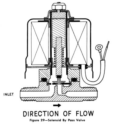
1953 Buick Solenoid By Pass Valve
The parts of the valve are the coil, coil cover, brass body, inlet and outlet connections which are 8h” male flare, orifice or stationary seat, movable seat, plunger, and plunger spring. There is also an orifice restriction in the out let side of the valve. The direction of flow through the valve is shown by a directional arrow on the underside of the body. The purpose of the valve is to relieve the pressure on the compressor when starting the engine of the car, and to by-pass the refrigeration cycle when cooling is not needed in the passenger compartment of the car. The coil receives its electrical energy from the battery when the “OFF-ON” switch on the control panel is in the “ON” position and the car thermostat is calling for refrigeration. The orifice restriction in the outlet side of the valve causes a reduction of pressure on the saturated vapor or liquid passing into the outlet line. This causes the saturated vapor to cool and any liquid to vaporize and cool before entering the compressor, thus preventing the compressor from overheating during by-pass operation.
Refrigerant Check Valve
This valve has a special duty to perform. Its purpose is to prevent liquid refrigerant from entering the by-pass and low pressure lines when the solenoid valve is open. This is a protection against possible damage to the compressor which might be caused by liquid entering the compression chambers of the pump. To see how it works, let’s Iook at the cutaway of the check valve.
It is a brass valve with a spring-loaded seat. It operates by pressure differences between each end of the valve. For example, when the system is refrigerating, the check valve is open due to the fact that the pressure in the con denser is slightly higher than that in the receiver. When the system is not refrigerating (by-pass valve open) the pressure in the receiver becomes the higher and the check valve closes. Note that arrows on the check valve body denotes direction of flow.
Refrigerant Sight Glass
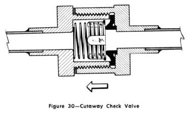
1953 Buick Cutaway Check Valve
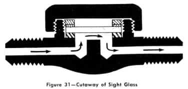
1953 Buick Cuta way of Sight Glass
In reality, the sight glass has no function to perform in the system. By this, we mean the system would operate just as well without it. However, it is a valuable addition to the high pressure liquid refrigerant circuit as it will save a Iot of time and eliminate some guesswork in diagnosing difficulties. It provides a quick and sure way of determining whether or not the refrigerant charge is sufficient. To better understand it, let’s Iook at the chart.
It has a brass body with the inlet and outlet threaded for 3/8″ flare nuts. The refrigerant passes through a small chamber with two small holes which is covered with a sealed glass window. It is so designed that a shortage of refrigerant in the receiver and liquid line will be indicated by the appearance of bubbles or foam beneath the glass. A screw-on metal cap protects the glass.
Connecting Refrigerant Lines
The refrigerant lines are formed from soft copper tubing. The high pressure line is 3/8″ outside diameter and the low pressure is 3/4″ outside diameter. Each line is in several sections. The sections of the low pressure line are joined by flare connectors which are located along the chassis channel. The dehydrator-filter serves as the connector for the high pressure line sections. All flare connections are made with double flare seats. This assures a better seal with less tightening pressure of the flare nut.
To prevent damage from vibration and friction, the lines are securely fastened to the chassis channel in speci
1953 Buick Air Conditioner Schematic View
al mounting clamps and sup ports with rubberized inserts.
Refrigerant Dehydrator-Filter
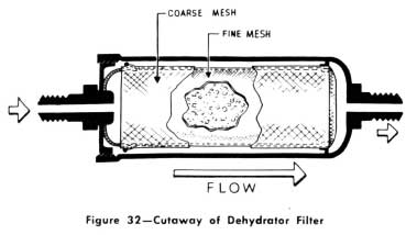
1953 Buick Cutaway of Dehydrator Filter
As the name implies, it has two duties. Its more important function is to accumulate moisture that may not have been sufficiently removed during the installation, or which may have entered the system during service operations. The importance of keeping the interior of the system free of moisture will be discussed in detail later in the program.
The second duty of the dehydrator-filter is to trap foreign matter, such as particles of dirt, copper filings and bits of solder, should such accidently remain in the system, so as to keep them from getting through the expansion valve or coil, and into the compressor.
Now, let’s learn how it performs its duties and see how it is constructed.
It is a steel tubular shell plated so that it is rust resisting and containing a quantity of de hydrating agent and two fine mesh screens.
The dehydrating agent is small particles of acetate coated calcium sulphate. Its ability to accumulate moisture is high in both efficiency and capacity. The dehydrating agent is contained within two screens, one within the other. The inner screen is 200 mesh and the outer 64 mesh. These screens prevent small particles of dirt or foreign matter from passing onto the expansion valve. The direction of flow through the dehydrator is marked with an arrow and the inlet connection is stamped with the word “IN.” No service should be performed on the dehydrator-filter itself.
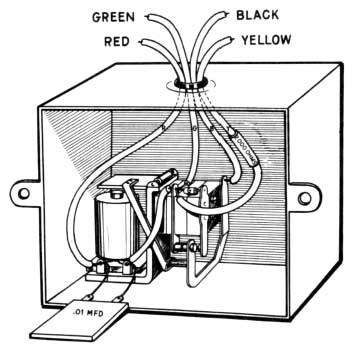
Control Panel
The purpose of the panel is to control the operation of the air-conditioning system. The controls are located on the instrument panel-just above the steering column. One knob is used to turn the air conditioning system “ON” or “OFF” and sets the blowers to “High” or “Low” while the other knob determines to an extent the degree of cooling that can be obtained within the car.
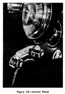
1953 Buick Control Panel
A relay is mounted on the rear of the panel and operates in conjunction with the thermostat to control the cut-“In” and “Out” of the solenoid by-pass valve.
Thermostatic Control
The solenoid by-pass valve which is connected to a tee in the condenser-to-receiver line and a tee in the compressor low pressure line allows “OFF” and “ON” operation of the cooling system. When open (i.e. electrically de-energized) refrigerant is by-passed and cooling effect is nil. When the valve is closed (electrically energized) the refrigerant system operates normally applying full cooling effect to the cooling coil. The function of the thermostat is to open and close this valve to maintain a constant temperature within the car. The mercury thermostat is located in the recirculated air grill and is controlled by the air leaving the passenger compartment. Because of its volume and velocity this “leaving” air is representative of the average temperature within the seating space of the car.
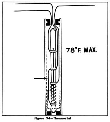
1953 Buick Thermostat
The thermostat which is mounted in the re turn air duct, is constructed like a mercury thermometer and, like a thermometer, the top of the mercury column rises and falls with changes of temperature. Platinum wires inserted through the glass of the column are used to accurately give an electrical “make” and “break” point. By its very nature, the temperature, (in this case 78 degrees) is very accurate and the differential between “make” and “break” is a small fraction of a degree. Thus the sensitivity makes the control quite active and the resulting car temperature even and consistent.
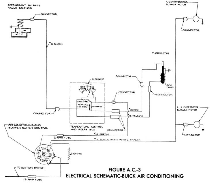
1953 Buick Air Conditioning Electrical Schematic
Relay
When the mercury column is high and cooling is needed, the relay is energized by current through the thermostat which in turn energizes the solenoid by-pass valve coil, closing the latter and allowing the refrigerant system to apply full cooling to the cooling coil.
When cooling is not needed, the mercury column is low and open circuited. The relay is then de-energized by the open mercury column and this in turn breaks the circuit to the solenoid valve. The latter is thus allowed to open and by-pass refrigerant, reducing cooling effect to nil within the car.
1953 Buick Relay in Thermostatic Control Circuit
You will note in the description thus far that a fixed temperature of operation (i.e. 78 degrees) is the point at which control is maintained. Now, in order to vary the temperature over a range so that the occupant may select other than 78 degrees to suit his own comfort conditions, a second electrical circuit is used. This circuit provides a heater winding around the mercury bulb with a variable rheostat external to the thermostat which controls the current to the winding on the tube. When a fixed current is allowed to flow through the heater winding a fixed wattage loss occurs at the mercury bulb surface thus locally heating the mercury above normal temperature. The column will then rise until a new and fixed heat balance occurs between the wattage gain and the heat dissipation at the bulb surface. The latter is a function of the temperature differential. Thus the mercury column is above the break point by the differential necessary to balance the wattage applied electrically. The air temperature or control point will then be reduced below the fixed setting by the amount of the differential. Thus the 78 degree tube may be “controlled” to operate at a maximum of 14° cooler or low of 64°.
By controlling the current to the heater winding, the tube may be made to operate at other (always lower) temperatures as desired, and each new setting will be stable and fixed.
There is still a further refinement used to “even-out” the temperature. In an automobile in which the heat Ioad is very large with respect to total air volume and the cooling capacity is correspondingly large, the air temperature rises rapidly when cooling is “OFF” and falls quite as rapidly when cooling is “ON.” Thus a quick response at the thermostat is necessary to prevent noticeable rise and fall of space temperature. In addition to the natural sensitivity of the tube which makes and breaks at a fraction of a degree, an “anticipator” circuit is used. In the schematic wiring diagram, this is the fixed resistor connected to the back contacts, or normally closed contacts of the actuating relay. Note that a shunt circuit to the main control rheostat is in effect when, but only when, the mercury is low in the tube. Thus, whenever the mercury drops below the control point, additional current is added to the normal control current. This small differential acts to make the mercury return more quickly to contact calling again for maximum cooling. This factor in effect causes the thermo stat to “anticipate” the fact that the car is warming up and will again need cooling quickly. The rise and fall of temperature is greatly reduced and the effect on the occupants is one of stabilized control.
The specifications for the various components of an electrical circuit are given below.
Condenser
Capacity .01 MFD
Purpose Reduction of induced voltage at break
Resistor
Resistance 2200 ohms +/- 10%
Wattage .5 watts
Purpose Reduce off cycle time and to smooth car temperature
Thermostat
Resistance of Heater Winding 800 ohms +/- 1 %
Nominal Rating of Tube (Max.) 78°
Adjustment 14° max. at 14 volts below 78° nominal setting Accuracy +/- 1/2 degree F.
Safe Outside Air Conditions 200°F. Max. / -35°F. Min.
NOTE: All data above is for 12 volt systems only.
This completes the 1953 Buick Air Conditioner construction and operation of the components in the Buick air conditioning system. Now, to put all of the air conditioning components together and learn just what takes place during a “cycle of operation.”

Thanks. My aunt had asthma and my uncle bought her a 1953 Buick with factory air. This car was the first I had ever been in with air conditioning and I was amazed by it. I was an early teenager at the time.