SECTION 8-A MANUAL STEERING AND LINKAGE
The manual steering gear and linkage for 1958 remains the same as was used in 1957.
SECTION 8-B POWER STEERING GEAR AND PUMP
8-1 PUMP SPECIFICATIONS
Relief valve opening, psi: 975 to 1075
8-2 GENERAL DESCRIPTION
Power steering for 1958 will be standard equipment on 50, 70 and 700 Series and will be offered as optional equipment on the 40 and 60 Series. All cars equipped with Air-Poise Suspension will be equipped with power steering.
The power steering gear remains unchanged from the 1957 after jobs. Two power steering pumps will be used in 1958, one for cars equipped with Air-Poise Suspension and one for cars equipped with power steering only.
8-3 DESCRIPTION OF POWER STEERING PUMPS
Except for the changes described below, the power steering pumps are functionally unchanged from 1957. The two pumps for 1958 differ in the mounting, method of driving rotor, reservoirs and pump bodies.
Power Steering Pump-Without Air-Poise
A bushing replaces the outer bearing in the pump body and a new pump shaft is retained to the rotor by a snap ring. See Figure 8-1.
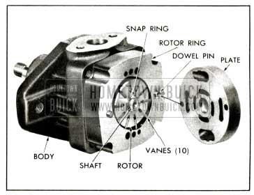
1958 Buick Pump Without Air-Poise
A new shaft oil seal is used because of the change in the shaft and the pump body.
Power Steering Pump-With Air-Poise
The power steering pump on Air-Poise equipped cars does not have a shaft and has a redesigned pump body which has no bushings. See Figure 8-2.
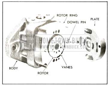
1958 Buick Pump With Air-Poise
The rotor of the pump is driven by the air compressor crankshaft which is splined to the rotor. An oil seal in the pump body prevents oil from leaking out of the pump around the compressor crankshaft.
Inside the pump reservoir is an oil reservoir for the air compressor that is designed to supply oil to the compressor for lubrication. The compressor reservoir has an inlet and an outlet connected to the compressor by drilled passages in the pump body. The pump reservoir is not interchangeable with the reservoir on pumps used on cars not equipped with Air Poise. See Figures 8-3 and 8-4.
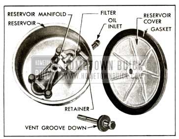
1958 Buick Pump Reservoir (Without Air-Poise)
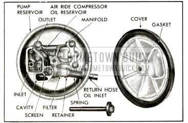
1958 Buick Pump Reservoir (With Air-Poise)
Oil returning from the gear enters the return hose oil inlet. Some passes through the filter into the pump reservoir while the rest flows up through a screen and over into a cavity. The cavity has a drilled hole in the bottom connected to the bottom of the compressor reservoir. Thus, the same oil level will be maintained in the cavity and the compressor reservoir. The excess oil that is supplied to the cavity flows over into the pump reservoir. If the screen and filter should become plugged, the pressure of the oil overcomes the spring tension and forces the retainer and spring away from the filter, allowing oil to escape between the filter and retainer.
8-4 DISASSEMBLY, INSPECTION AND ASSEMBLY OF POWER STEERING PUMPS
Power Steering Pump-Without Air-Poise
The disassembly, inspection and assembly remains the same except for the following changes.
- To remove shaft from pump body the snap ring that retains shaft to rotor must be removed.
NOTE: To remove and install the oil seal the pump must be disassembled and shaft removed from body. - The oil seal is removed from body using Remover, J-5822, installed on suitable slide hammer. See Figure 8-5. Caution must be used so that the outer bushing is not damaged when removing seal.
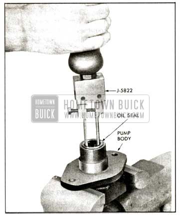
1958 Buick Removing Oil Seal
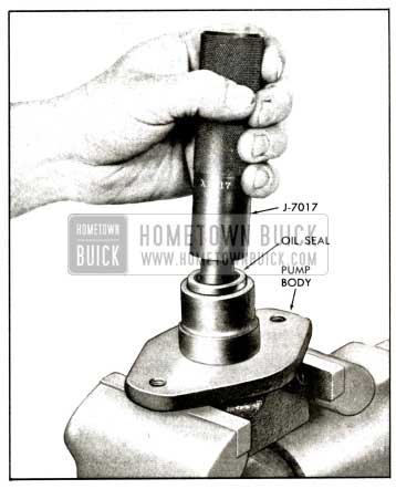
1958 Buick Installing Oil Seal
Power Steering Pump-With Air-Poise
CAUTION: The pump reservoir cover should not be removed when engine is running as oil returning from the air compressor will spray out.
The disassembly, inspection and assembly is very similar to the pump used on cars not equipped with Air-Poise except for the following changes.
- To remove pump from engine and air compressor, remove oil from reservoir, disconnect oil hoses and remove compressor pump assembly rear mounting bracket by disconnecting from intake manifold, left cylinder head and pump bracket. See Figure 8-7.
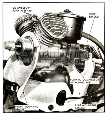
1958 Buick Compressor-Pump Assembly Mounting
Then re move two pump to compressor attaching bolts and carefully separate pump from compressor.
NOTE: If difficulty in separating pump from compressor is encountered, insert screw driver between bolt recess on compressor and pump body , then carefully pry apart. See Figure 8-8.
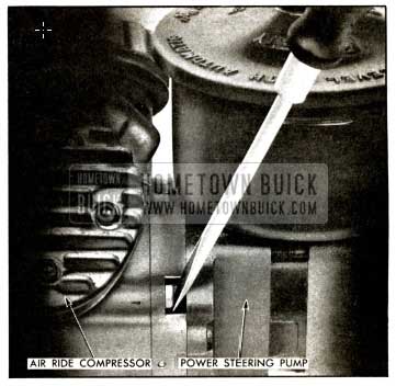
1958 Buick Separating Pump from Compressor
- The oil seal is removed from pump body using Remover, J-5822, installed on suitable slide hammer. See Figure 8-9.
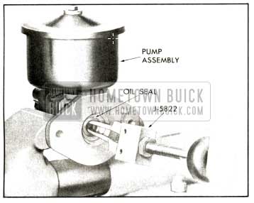
1958 Buick Removing Oil Seal View
Caution must be used so that the pump shoulder will not be damaged when removing seal.
NOTE : To remove and install oil seal in pump body, it is not necessary to disassemble pump.
- A new oil seal is installed using Seal Installer, J-7111. See Figure 8-10.
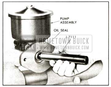
1958 Buick Installing Oil Seal View
NOTE: If pump does not seat properly against compressor, hold pump firmly and remove guide pins. Then rotate pump slightly while applying pressure at rear of pump.
- To complete assembly of pump to compressor and engine, reverse step 1 above. Add oil, run engine and check for leaks. Recheck oil supply and add oil as necessary to bring to level.
Leave A Comment
You must be logged in to post a comment.